The Dunstable Portland Cement Company Ltd was formed in February 1925 and opened its plant during 1926 only 4.6 km from Sundon, then well-known to be Britain's lowest-cost plant, and using essentially the same raw materials. Shortly after commissioning, The Engineer (CXLV, January 27, 1928, pp 92-94, 104; February 3, 1928, pp 120-123), published an in-depth account of the plant. It is believed to be out of copyright. Although not mentioned in the article, the machinations associated with the formation of Red Triangle were under way at the time, and perhaps for this reason, the article was more than usually fulsome. Becoming, by 1931, part of the Blue Circle Group, the plant continued in operation until 1971, never achieving the low-cost status to which it aspired.
The text has been transcribed from the original article. The figures have been presented in the order referenced in the text rather than numerical order.
Values of imperial units (as of 1928) used in the text (alphabetical order): 1 acre = 0.40468424 Ha: 1 ft = 0.30479947 m: 1 gallon = 4.5460756 dm3: 1 HP (horse-power) = 0.7456998 kW: 1 inch = 25.399956 mm: 1 psi (pound-force per square inch) = 6.89478 kPa: 1 ton = 1.01604684 tonne: 1 yard = 0.91439841 m.
The Dunstable Portland Cement Works.
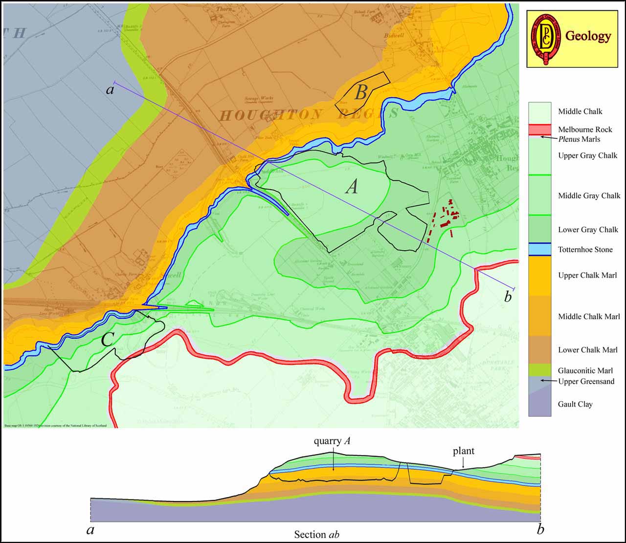
By courtesy of the Dunstable Portland Cement Company, Ltd., we have recently had opportunities of making thorough inspections of the new works which have been established by it just outside the town of Dunstable in Bedfordshire. That part of the country is strongly undulating, and is particularly interesting in that the three chalk strata—upper, middle and lower—outcrop at the surface at points which are in some cases close to one another. On the land on which the works have been built there are, but a short distance apart, outcrops of the middle and lower chalk (Note 1), and their chemical compositions are such that when mingled together in the correct proportions, the mixture contains, without any further additions, the exact ingredients required for the manufacture of Portland cement of high quality (Note 2). Both chalks are easy to work, for both can be dealt with in wash mills after being passed through kibbling rolls to break up the lumps as quarried, and neither contains any flints, the occurrence of flints being confined to the upper chalk. There is moreover, but little overburden. In some cases the chalk comes practically to the surface; in others, it is only covered by a few inches of soil; and nowhere does the depth greatly exceed 18 in. The site therefore may be looked upon as being ideal from the point of view of raw materials, and the company owns some 600 acres, with usable material going down for perhaps hundreds of feet before the greensand which underlies it is reached (Note 3).
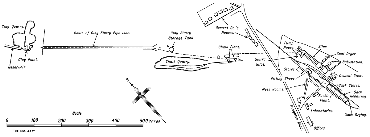
Figure 1: Diagrammatic plan of Dunstable Portland cement works
In addition to their advantage regarding raw materials, however, the works are situated on a main road (Note 4), from which there is easy access to many towns, large and small, within economic carrying distance by motor lorry, those towns including Bedford, Luton, &c., all of them rapidly growing and likely to need large quantities of Portland cement, while London is also within easy road delivery. Furthermore, the site is in direct connection by the line marked D in Fig. 2 with the London, Midland and Scottish, and the London and North-Eastern railway systems (Note 5), so that coal and gypsum are readily brought to it, and cement, as readily, sent away. At the moment, the company has not got them, but it intends shortly to order a fleet of 20-ton bottom-discharging railway wagons, which will bring coal from various collieries in the Midlands—none of them at prohibitive distances away—empty their contents into a hopper, and then be hauled back to fetch further loads. In this connection it may be explained that extensive sidings have been provided—see E in Fig. 2—for the temporary use of loaded or empty wagons, and that the company has, for shunting purposes, an exceedingly handy standard-gauge locomotive made by the Sentinel Waggon Works, Shrewsbury.
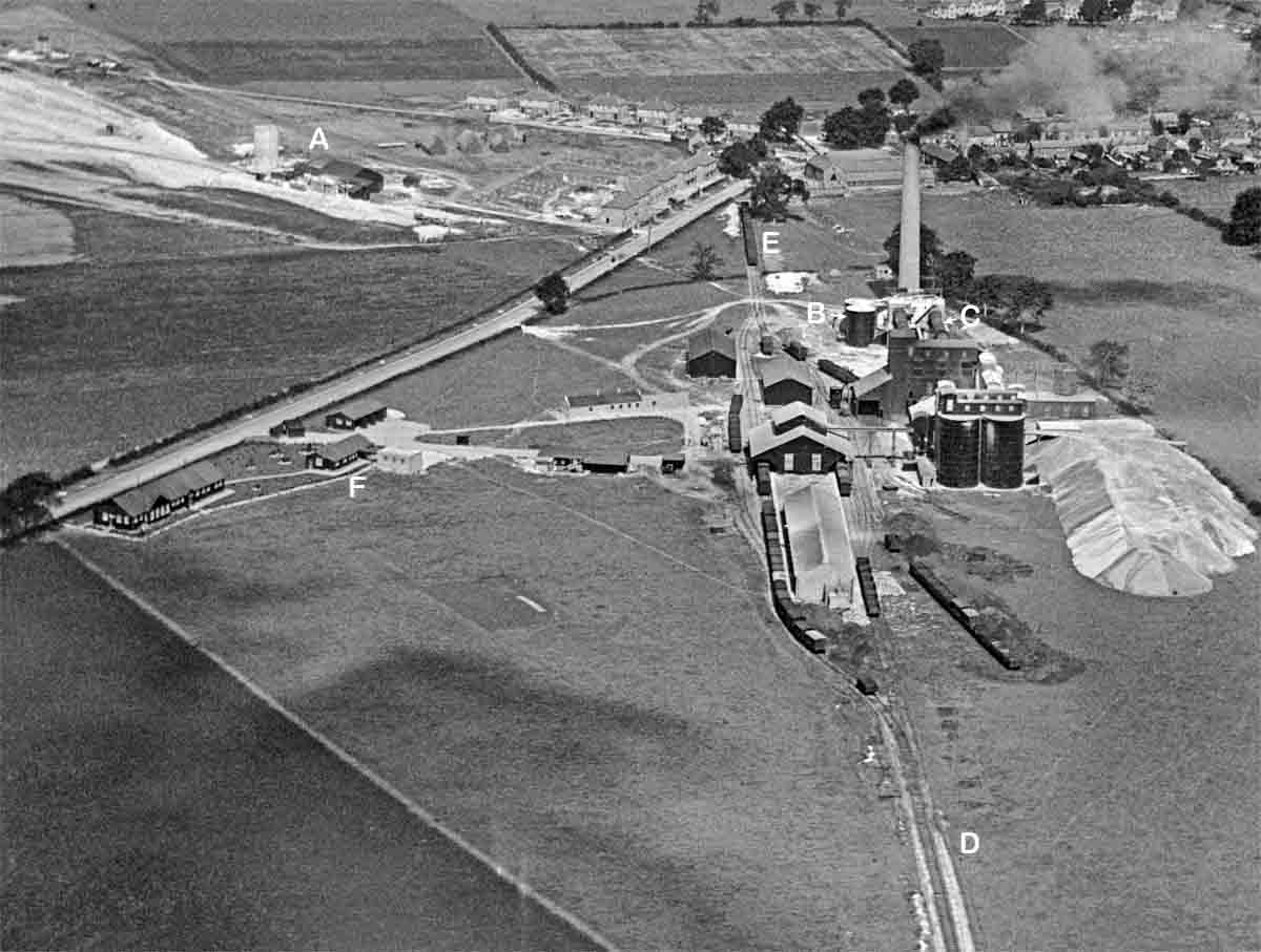
Figure 2. Birdseye view of works
As a final advantage, it may be said that during a large portion of the year there is a superabundance of water draining from the site to a sump, from which what is not required for the time being is pumped into a reservoir, which has a capacity of 100,000 gallons, and commands one set of wash mills. Arrangements have also been made by which, during the drier months of the year, the effluent from a nearby works (Note 6) may be drawn upon. So that from every point of view it is hard to imagine a better position in which to found a cement factory to operate on the "wet" system, which has been chosen by the consulting engineers, Messrs. Maxted and Knott (Note 7), of 82, Victoria-street, S.W., by whom the works have been designed. Furthermore, it may said at the outset that the works have been laid out in a thoroughly practical and apparently most economical manner, and that the whole of the machinery, the chief contractors for which were Edgar Allen and Co., Ltd., of Sheffield, is of the highest class.
The respective chemical compositions of the two kinds of chalk were, at the time of our visits, such that approximately two-thirds of the middle chalk and one-third of the lower chalk were required to produce the correct mixture for the manufacture of Portland cement. For convenience in describing the plant and processes, we shall use the terms "chalk" and " clay", as is commonly done in the works, to describe the two materials, though "clay" is not actually a correct description to apply to the marl-like lower chalk (Note 8). It may be possibly found in time when the excavations of the two strata have proceeded far enough for the dividing line or zone between the two strata to be reached, that the material as excavated will, without any admixture or adjustment, have the correct composition for cement making, but at present, as we have said. approximately two parts of chalk are required to one part of clay. Consequently, we find, as might be expected, that the plant for dealing with the clay is of just half the capacity of that for dealing with the chalk. Both the clay and the chalk are led to the works in pipes in the form of slurry, being mixed in the desired proportions at a point some 270 yards away, as will be explained in due course. Our description will be more readily understood by the aid of the accompanying plan and of Fig. 2, which is reproduced from a bird's-eye photograph taken from an aeroplane.
The clay is at present being quarried at a point some 800 yards to the left of the point marked A in Fig. 2 (Note 9), and at an elevation of some 150 ft. below it. The clay is being got out by a steam-operated Ruston caterpillar digger, having a bucket with a capacity of just over a ton. It is delivered direct into a train of four side-tipping steel trolley wagons which run on 2ft.-gauge lines laid on the floor of the quarry. For the most part the material is soft and homogeneous and consistent in chemical composition, though very occasionally shallow bands of much harder stuff are encountered. The chemical composition of these harder bands is almost identical with that of the surrounding material, but as the blocks into which they are broken by the digger are hard enough to put too severe a stress on the kibbling rolls, which were, as a fact, not designed to deal with them, they are removed by hand before the material is shot into the wash mill. The quantity of these hard lumps is not very large, however, the pile representing some nine or ten months' working of the plant, not being of inconvenient proportions.
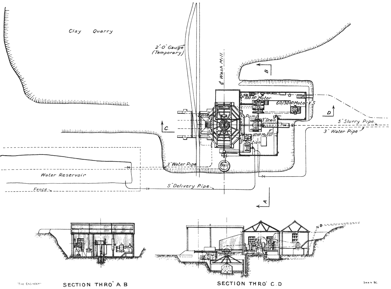
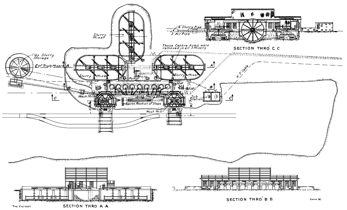
Figure 3: Plan and sections of marl quarry plant
Two trains of light trolley wagons are at present being operated. When one train is full it is hauled by a small petrol locomotive from the quarry to the wash mill, a distance at the moment of some couple of hundred yards. Having done the journey with loaded trucks, the locomotive picks up the train of empty trucks and hauls it back to the quarry, sidings being arranged in the lines of railway to render these operations possible. Arrived at the wash mill, the loaded trucks are tipped one by one and their contents shot into a hopper over the kibbling rolls—Fig. 3. These rolls are actually two sets of fingers curved to sickle form and mounted on two parallel horizontal shafts. The fingers on the two shafts interlace with each other, and the two shafts revolve at different speeds, one making 1.9 revolutions a minute and the other 0.95. The machine works exceedingly well (Note 10), the material being broken up into pieces of such sizes that they are readily dealt with in the wash mill. With regard to the latter, nothing much need be said, saving that it is 20 ft. in diameter and that its arms are revolved at a speed of 20 revolutions per minute, by means of a three-phase alternating current electric motor of 100 horse-power. The slurry discharged from the wash mill is forced by a three-ram plunger pump through 720 yards of 5 in. piping to a concrete storage tank built near the point A in Fig. 2, the difference in level being about 120 ft. It was at first intended that both the wash mill and the pump should be operated by the same motor, but it was discovered, when operations were started, that the "clay" formed a slurry of such a "stiff" consistency that one motor would be overloaded if it drove both mill and pump, and, accordingly, an additional motor was installed to drive the latter. The viscosity of the slurry is, in fact, much greater than is ordinarily experienced with slurries made from chalk marls in other parts of the country, and it made itself felt in other parts of the works as well as in the clay pumping plant (Note 11).
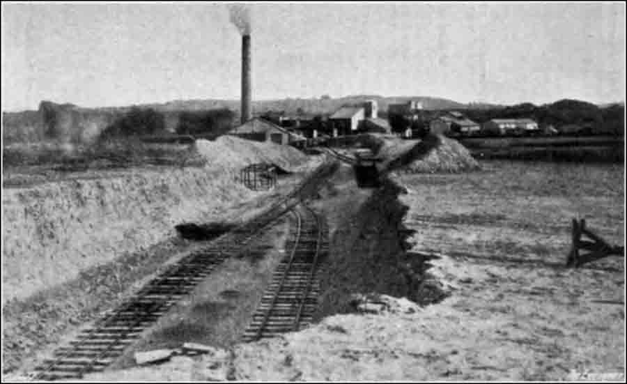
Figure 7: View towards the washmills from the chalk quarry, with the main plant behind.
The chalk is dealt with in the buildings at the point A in Fig. 2. At the present moment the working face in the chalk quarry is about 200 to 300 yards away to the left (Note 12), and the two points are linked together by exceptionally well laid standard-gauge lines of rails, Fig. 7. The overburden is being removed by means of a handy little caterpillar runabout tractor, which hauls a set of three-scraper soil removers termed Baker Maney scrapers, and was supplied by Tractor Traders, Ltd., Smith's-square, Westminster. The equipment is worked by two men—a driver and a man to operate the scrapers. On arriving at the point from which it is desired to remove overburden, the scraper operator first of all releases a catch holding the leading scraper free of the ground, so that the latter revolves on trunnions till its cutting edge engages with the surface of the ground and penetrates below the latter to a fixed amount. As the scraper is dragged forward, its container rapidly fills, when the cutting edge is automatically lifted from the ground. The operator then puts the second scraper to work, and subsequently the third. The train then proceeds to a dumping place where the material removed is automatically discharged, and goes back again to continue operations. The overburden is neatly and cleanly removed by this method, and we are assured that the cost of doing the work is remarkably low. In some parts it is only necessary for the ground to be traversed once, since, as we have explained above, the overburden is, in places, very shallow. In other parts, however, it is necessary to go over the ground more often, but taking all that into account, the cost of removal compares most favourably with that of any other method.
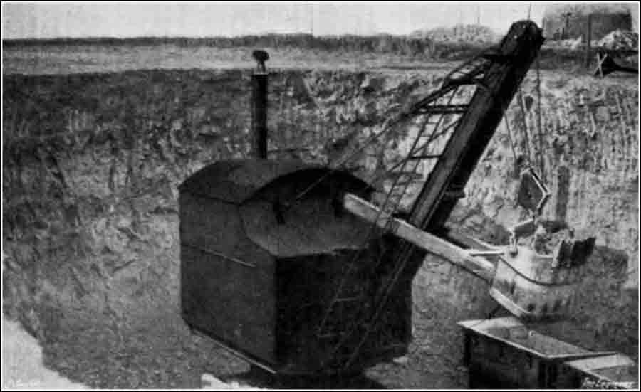
Figure 6: Ruston steam excavator at the chalk face. The remains of the Houghton Regis windmill is rear right.
The chalk is quarried by means of a Ruston steam caterpillar digger, Fig. 6, page 104, which has a capacity of about 2 tons per stroke. The material, which is greyish white on being first exposed, and is of a fairly hard nature, is dumped direct into a train of two drop-sided tipping railway trucks, and taken direct to the chalk slurry works, by means of a petrol-driven locomotive made by the Motor Rail and Tramcar Company, of Bedford. Arrived there, the contents of each truck are discharged into one or other of the hoppers over two sets of kibbling rolls, of a type identical with that at the clay mill. Beneath each set of rolls is a wash mill of the ordinary type, 20ft. in diameter, the spider of which is, in each case, revolved at 20 revolutions per minute by means of a 100 horse-power alternating-current motor. While the chalk is being washed down, clay slurry, in the proportion arranged by the works chemist, is allowed to flow by gravity from the storage tank, referred to above, into the mills where it becomes thoroughly mixed with the chalk to form a thick slurry of a dark cream colour. The chalk plant is shown in Fig. 4.
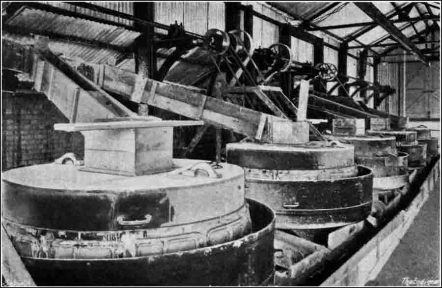
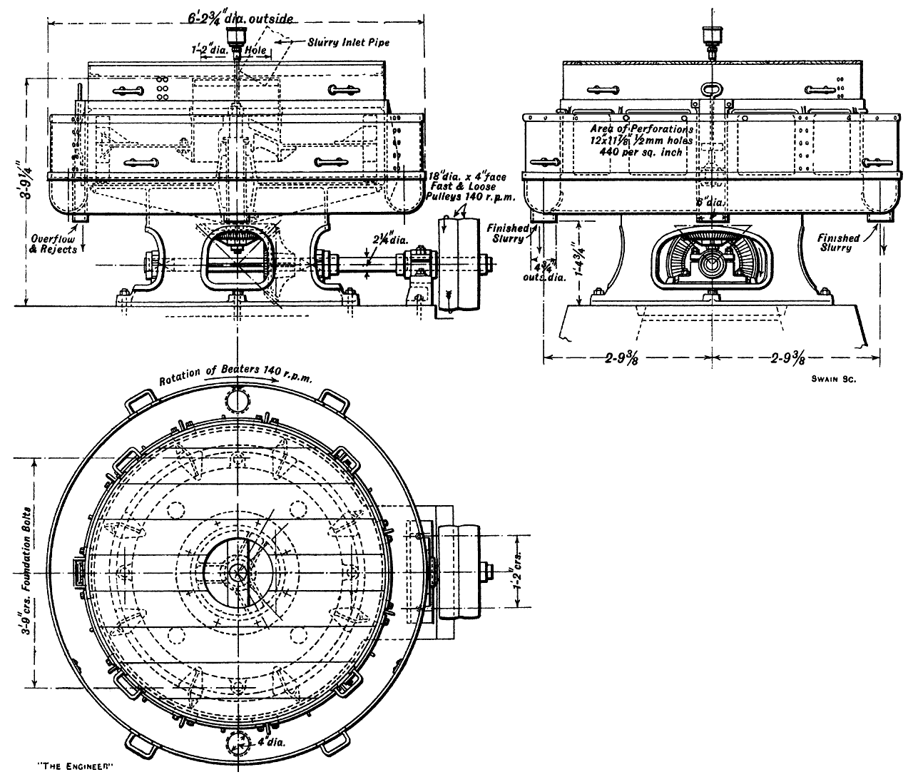
Figure 8: Set of screening mills (9 in total) for sieving the slurry, returning unground material to the washmills
The discharge from the wash mills flows through screens in the ordinary way into a common sump into which dip the buckets of a slurry lifting wheel 28ft. in diameter (Note 13), which is revolved at a speed of 5 revolutions per minute. The buckets of the wheel discharge the slurry at the top into a wooden trough through which it flows into a header leading to a battery of nine slurry separators, Fig. 8, which are operated by belt from shafting which, in turn, is driven by two 50 horse-power motors, one at each end, and from which the lifting wheel is also driven. Drawings of one of the separators are given in Fig. 5 (Note 14). The machine comprises a vertical spindle driven by bevel gearing from a countershaft. Keyed to the vertical spindle is a hollow spider, through which the slurry is fed, and bolted to the spider is a horizontal beater plate carrying cast steel beater brackets and spring steel beaters. This portion revolves inside a cast iron casing, and by centrifugal force throws the slurry on to a series of sieves round the periphery of the casing. The fine slurry is forced through these sieves and flows round the annular trough outside the casing through two outlets for the finished slurry. The tailings or rejects from the screen flow out through a special opening in the casing, and are returned to the wash mill for further grinding. The direction of the rotation of the beaters is shown on the plan, and the speed of the machine is 140 revolutions per minute.
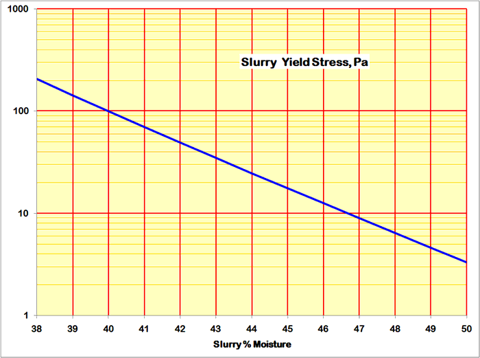
The discharge from these separators is into a wooden trough from which any one of three mechanical mixers which are arranged to form three arms of a cross—may be fed. The mixers are tanks, sunk in the chalk and lined with brickwork (Note 15). Each is 62ft. long and 30ft. wide, with rounded ends. Each was originally furnished with a set of three mechanical stirrers, each set being slowly revolved by means of 20 H.P. motors through gearing. As a matter of fact the centre of the three stirrers has now been removed from each of the mixing tanks, for the consistency of the slurry, to which we have already referred, was so thick and viscous that it was found that the motors were rather overloaded when three stirrers were at work, notwithstanding the fact that the same size of motor is operating precisely similar mixers in other parts of the country with slurries of ordinary consistency. Moreover, it was found that two sets of stirrers kept the slurry amply agitated (Note 16), there being no tendency for the more solid particles to settle to the bottom. We may here mention that the slurry in the mixers, and indeed as it is supplied to the kilns, contains about 40 per cent. of moisture (Note 17). We may also explain that samples of the contents of these tanks are frequently taken by the works chemists and analysed, any necessary alteration in the proportions of chalk and clay being then made by the attendants adding more of one or the other—as the case may require—to the contents of the wash mills. As a matter of fact, however, as far as our observations went on the occasions of our visits to the works, it is very rarely indeed that any change in the proportions is required. In spite of the fact that the men in charge of the wash mills are dealing with such varying quantities as truck loads made up of discharges of the contents of the buckets of mechanical diggers—which may or may not be all of the same weight, and may not always arrive at the point of discharge at absolutely the same intervals—they get, in time, to be extraordinarily expert in so apportioning the ingredients that a slurry of consistently even composition is obtained. We have noticed the same thing in many cement works, and when it is considered within what comparatively narrow limits variation of the constituent ingredients in Portland cement is permissible, the skill acquired by these men is all the more remarkable. It would almost seem that they almost know by the look of the slurry whether it is "right" or "wrong" (Note 18).
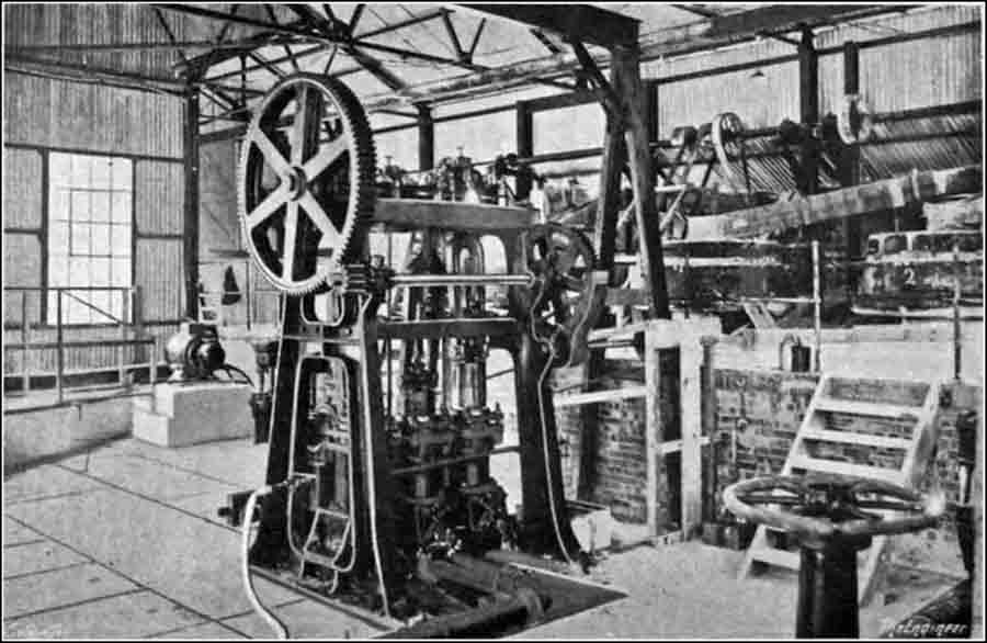
Figure 9: Edgar Allen 3-throw pump for transfer of slurry from the quarry washmills to the kiln-feed storage tanks. The slurry separators are in the background.
The contents of the mixers can be discharged into a sump formed where the three ends of the mixers converge together. From the sump the slurry is pumped by a three-throw plunger pump having rams 10¾ in. diam. and 15 in. stroke, Fig. 9, to the cement works proper through some 270 yards of 6 in. steel piping. The pump is driven by a 20 H.P. motor. The piping is laid under ground, and where it passes under the roadway seen in Fig. 2 it is taken in one of two 12 in. diameter earthenware pipes laid in concrete. The slurry is discharged into either one of two storage silos—see B in Fig. 2—which are circular vertical riveted steel tanks, 24ft. diameter by 53 ft. 9 in. total height, with funnel-shaped bottoms (Note 19). The two silos contain enough slurry for thirty hours' operation of the kilns. In these silos the slurry is kept agitated by means of compressed air, for which purpose a three-cylinder Broom and Wade air compressor, driven by a 50 H.P. motor through gearing, has been installed. The air is delivered at the bottoms of the silos at a pressure of about 25 lb. per square inch through special agitation nozzles and valves by means of which it is possible to turn on or cut off and control the supply at will. The air thus supplied under pressure rises to the surface of the slurry in great bubbles, which cause sufficient agitation to keep the slimy mass thoroughly mixed.
In a house near the bases of these silos there are, in addition to the air compressor, two sets of three-throw plunger pumps with rams 8⅝ in. in diameter by 16 in. stroke, driven by a 20 H.P. motor. Ordinarily only one of these pumps is in operation, the other being kept as a stand-by. It lifts the slurry from a sump into which it can flow by gravity from either of the two silos, or into which if need be the slurry coming from the mixing plant can be discharged direct, and delivers it into two measuring tanks, arranged immediately above the charging ends of the two kilns. The pumps are capable of lifting considerably more slurry than is actually required for feeding the kilns, and considerably more than that amount is continuously pumped, the surplus, after flowing over a weir in each measuring tank, which gives a fixed head in the latter, being returned in a constant stream to the storage silos, a process which assists in keeping a good average mixture of the chemical constituents of the raw material.
The desired quantity of slurry is fed into the kilns by allowing the slurry to flow through an orifice of prescribed cross-sectional area under the influence of an accurately maintained pre-determined head (Note 20). There are, of course, other methods of arriving at the same result, several of which we have described in the past. but that which is employed at Dunstable is very simple, is perfectly satisfactory, and, moreover, can be relied upon to operate with a minimum of supervision. As long as the flow of slurry is maintained considerably in excess of the requirements of the kilns, practically all the attention that is required is to make sure from time to time that the chute from the measuring tank to the kiln is kept clear. Alteration of the output of the kilns can be effected by varying the area of the orifice. Experiments have been made with the Rigby-Allen slurry-atomising process, by means of which the slurry is forced under pressure through nozzles into the kilns instead of being delivered in the manner described above. Although we understand that the experiments with this plant have been promising so far as they have gone, pointing to an increased output from the kilns and a more economical use of fuel, the apparatus was not working when we visited the works, but we understand that it will be in operation in the near future (Note 21).
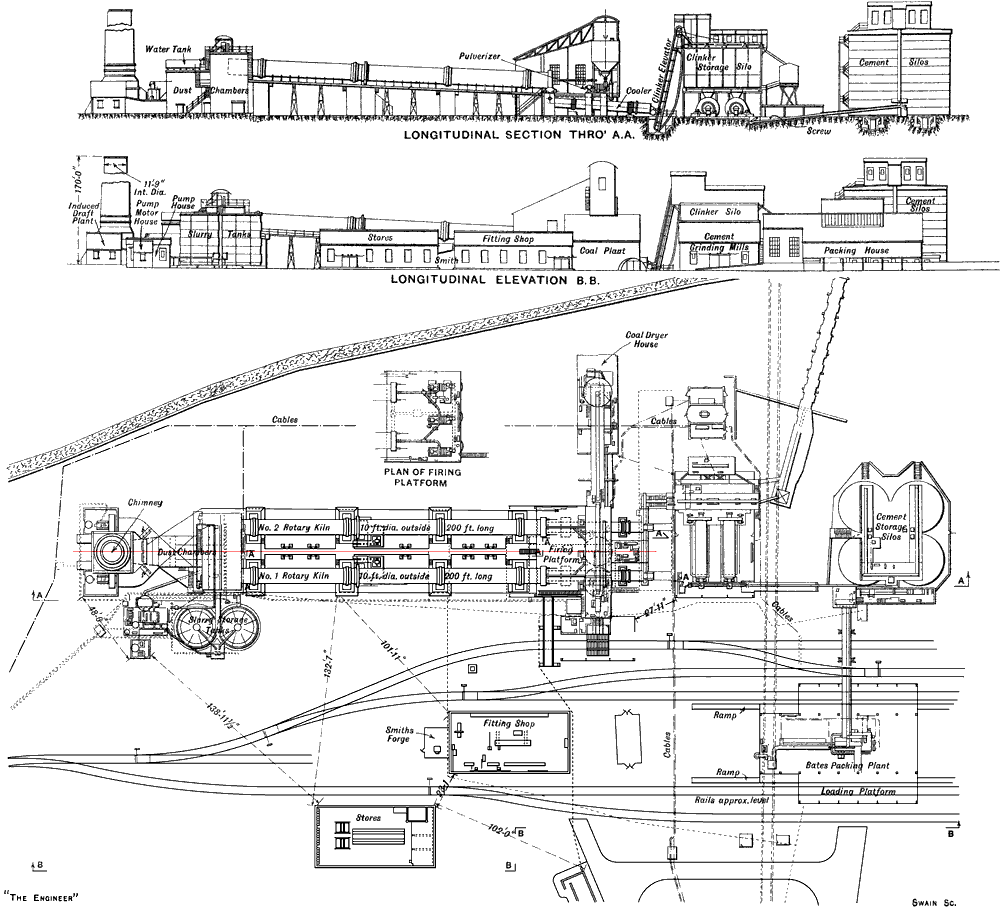
Fig. 10: Longitudinal Section, Elevation and Plan of Dunstable Cement Works. View in higher definition.
Above we had got as far in our description of the Dunstable Portland Cement Works as the slurry silos, and the method of feeding the slurry into the kilns. There are, as was intimated, two kilns—C, Fig. 1 ante. They are, of course, of the rotary type, and each is 200 ft. long by 9 ft. 8½ in. diameter throughout, there being no enlargement in diameter in the firing zone. It may be remarked in passing that, though, when they were first introduced, great things were claimed for the kilns with enlarged portions for the firing zones, those claims would seem not to have been substantiated, since of recent years many parallel kilns have been installed (Note 22).
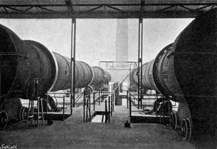 Figure 13: The Kilns from the Firing Platform - No 1 to the left. |
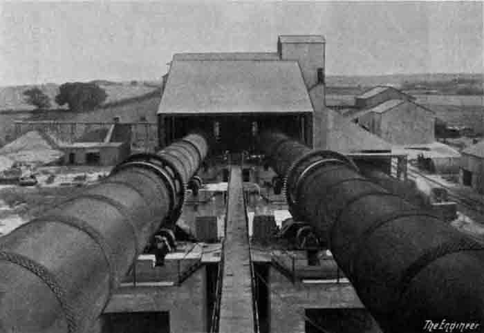 Figure 14: The Kilns from the Feeding End - No 1 to the right. |
There is nothing particularly novel in the construction of the kilns to which to draw special attention. They are given an inclination of 1 in 24, and are carried in the ordinary way on four cast steel tires, 16 in. wide, one near each end with the others spaced at regular intervals, which each bear on large rolling wheels free to revolve, the lower portions of which dip into oil and water troughs. At the time of our last visit, each kiln was revolving about once every 95 seconds, and we were informed that the output of each was upwards of 1000 tons of clinker per week (Note 23). The driving gears are of cast steel throughout, and all the wheels are machine cut, with the exception of the large spur ring which embraces the kiln and the pinion which gears with it, both the latter being machine moulded. Each kiln is driven by belt from a 60-30 H.P. induction motor capable of a speed variation of from 725 to 560 revolutions per minute, the variation being effected from the firing platform by the man in charge of the kilns (Note 24).
The firing hoods of the kilns are of Messrs. Edgar Allen's standard type and do not call for any special comment. They are, as usual, furnished with wheels running on rails, by means of which they can be withdrawn from the ends of the kilns. Powdered coal is used for fuel, and the powdering of the coal is effected in three turbo-pulverisers made by Clarke, Chapman and Co., Ltd., each of which is driven direct by a 150 H.P. motor running at 1470 revolutions per minute—see Fig. 15 (Note 25). One pulveriser is arranged opposite the end of each kiln, and the third unit is placed midway between the first two, and the delivery piping and valves are such that the third or central pulveriser, which ordinarily remains as a standby, may be used to feed either of the kilns. Hot air from the coolers is supplied to the pulverisers and the air suction ducts leading to the kilns are also connected to the cooler hoods. When the works were first put into operation, the pulverisers were fed with raw coal taken direct from the storage heap, and we are informed that, during the coal dispute of last year, the coal, as delivered, sometimes contained as much as 20 per cent. of moisture, but that the pulverisers despite these difficult conditions continued to work without interruption. However, a coal dryer has since been installed (Note 26). The coal used for firing the kilns is brought on to the site in railway wagons, the wagons being shunted so as to come over a grating above a large underground hopper into which dips a continuous bucket conveyor. The latter lifts the fuel, which is in the form of small slack, to a floor arranged above three large riveted steel hoppers, one of which is over each of the three pulverisers on the kiln-firing floor. Each of these hoppers contains 75 tons of coal, and the discharge from the elevator is into a swing tray conveyor, which delivers it at will into either of the three hoppers, or, alternatively, transport it along to the far end of the building, where it may be taken in hand by a further conveyor and discharged into a hopper, capable of containing 100 tons, arranged above the coal-drying building. The coal dryer, which, as explained earlier, is a comparatively recent addition, is of the Edgar Allen Class 8, double-shell type. It is 5 ft. in diameter and 30 ft. long, and has a coal-fired furnace with double doors. The coal to be dried is fed into the drum from a revolving table, the delivery being into a screw conveyor and thence by means of bucket elevators to the hoppers above the kiln floor, into which it is delivered by means of a spiral conveyor.
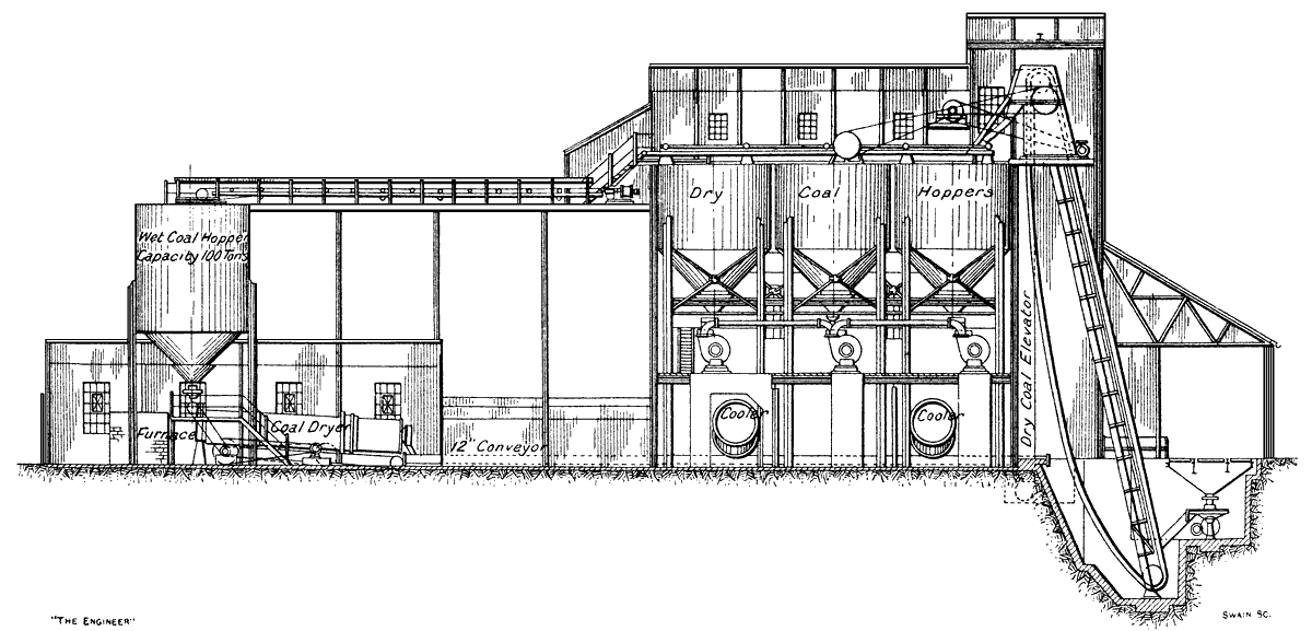 Fig. 11: Section through Coal Handling and Drying Plants. |
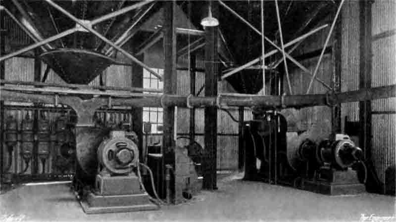 Fig. 15: Coal Pulverisers on Firing Platform. Clarke Chapman Turbo-pulverisers - No 1 to the right and the common spare to the left. |
The hot clinker from each kiln is discharged into a cooler 6 ft. in diameter and 60 ft. long, the coolers being arranged in a direct line with the kilns (Note 27). The clinker therefore as it comes from the kilns is taken on in a straight line towards the grinding mills, and not, as is done in some cement works, led back under the kiln in order to save space. The coolers are of quite ordinary construction, and each is driven at a constant speed by a 10 H.P. motor. At the discharge end of each cooler is a measuring device—Fig. 17—which is furnished with a counter, so that the volume of clinker produced is recorded (Note 28). The discharge from both coolers is into a horizontal swing tray conveyor (Note 29), which is controlled by an air dashpot, and which, in its turn, delivers the clinker into the boot of a continuous bucket elevator. The latter raises the clinker to the top of an adjoining building, the upper part of which forms a large storage silo (Note 30), while the grinding machinery is at the ground level. At the top of the building there is a horizontal swing tray conveyor of the same type as that just referred to as receiving the discharge from the coolers, by means of which the clinker is delivered into the silo below or taken on to the far end of the building, where it may be discharged down a shoot into a hopper erected on a wooden staging outside the building, with its floor some 20 ft. from the ground. On this staging, which is furnished with a weighing machine, run narrow-gauge lines of railway along which trolleys. after receiving a weighed charge of clinker from the hopper, can be run on to outside storage heaps and discharged. The elevator and conveyor in this building are both driven by one 20 H.P. motor, arranged on the top floor. A section through the grinding building is given in Fig. 19.
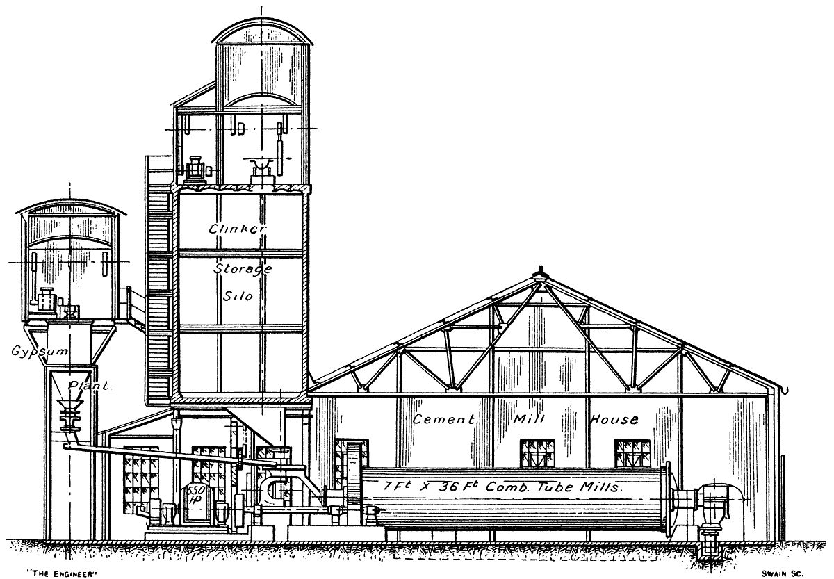 Fig. 19: Section through Clinker Grinding Department. |
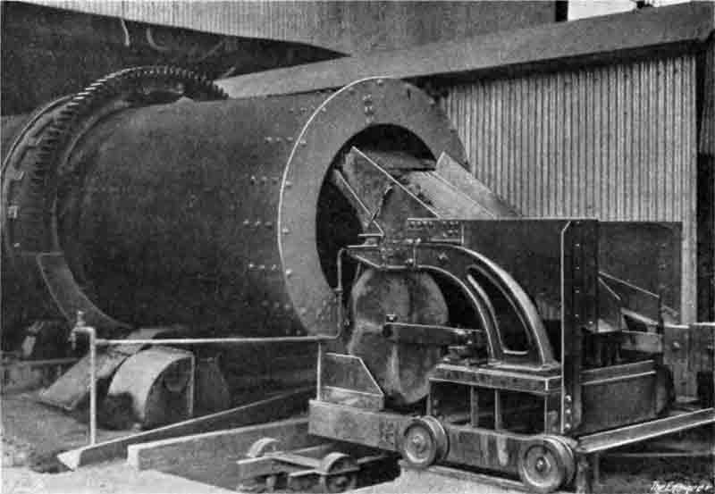 Fig. 17: Clinker Measuring Device at Discharge End of Cooler. |
The grinding machinery consists of two Edgar Allen combination tube mills, each 7 ft. in diameter and 36 ft. long. This type of mill—Fig. 16—has already been described in our columns and need not here be referred to in detail. Each is driven through single-reduction double-helical machine-cut cast steel gear, which is contained in special dust-proof casings. The pinion countershafts are each connected. through flexible couplings, with the shaft of a 550 horse-power motor. We shall refer to these motors again later. The clinker, which is led down chutes from the silos above, is supplied to the tube mills by means of an adjustable table feed in the usual way, a slight sprinkle of water being sprayed on to the tray conveyor. The necessary quantity of gypsum is added mechanically to the clinker at the inlets to the mills.
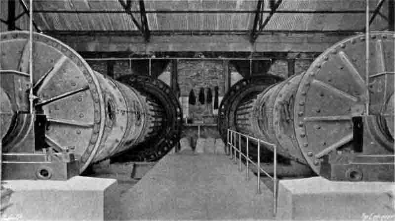
Fig. 16: Combination cement-grinding Tube Mills. No 1 to the left.
The finished cement as it comes from the mills is delivered into a spiral conveyor, which takes it out of the clinker building to the cement storage silos. The latter, of which there are four, arranged close together so as to occupy the four corners of a square, are of riveted steel plate. 30 ft. 6in. in diameter by 50 ft. high. Each silo holds 1500 tons, so that the total storage available is 6000 tons (Note 31). The delivery from the spiral conveyor is into the boot of a totally enclosed bucket elevator, which raises the cement to a covered-in floor formed above the tops of the silos, the discharge being into further spiral conveyors which deliver the cement into either of the four silos at will. Below the silos are two tunnels in which valve-controlled chutes lead down to spiral conveyors, one on each side of each tunnel, so that cement can be drawn from any desired silo. The conveyors take the cement to an elevator, which lifts it and discharges it into a further conveyor, which, finally, delivers it into hoppers arranged in the upper part of the dispatch shed. The latter is a roomy building which has on each side of its loading platform a standard gauge siding, so that railway wagons can be loaded direct. On the loading platform, in addition to ten valve-controlled spouts for filling sacks by hand, there are two Bates' valve bag packers—Fig. 18—each capable of packing 25 tons of cement per hour into sacks, the sack mouths being closed by a twisted wire. As each sack is filled, it is run down a slide on to a hand barrow, on which it is first run to a weighing machine and then taken direct into a railway van drawn up to the platform for the purpose, or to another part of the loading platform, where it can be loaded on to carts or lorries for dispatch by road.
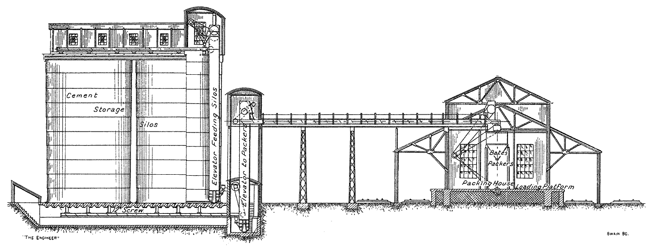 Fig. 12: Cement Storage Silos and Packing House. |
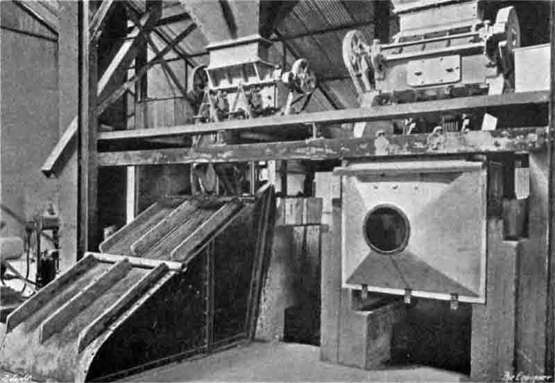 Fig. 18: Bates Valve-bag Cement Packers. |
Reverting now to the kilns, it may be explained that the hot gases, after passing through the kilns, are drawn downwards by means of two induced draught fans—one for each kiln—through spacious baffled depositing chambers where a very large proportion (Note 32) of the dust in suspension is thrown down. This dust, if it were not removed in this manner, would not only cause a nuisance in the neighbourhood by covering the vegetation, &c., in the surrounding country after being taken up by the draught and discharged from the chimney, but it would also represent a very considerable loss, since it consists almost entirely of partially burnt slurry. Arrangements have therefore been made by which the dust deposited in the flue chambers is withdrawn by spiral conveyors and led to a sump formed below the floor of the building which contains the pumps that feed slurry to the kilns. In that sump there is a revolving stirrer by means of which the dust is mixed with the slurry delivered from the slurry silos and is again fed into the kilns (Note 33). The induced draught fans were made by Davidson and Co., Ltd., of Belfast, and each is driven by a 40 H.P. variable-speed motor running at 362 revolutions per minute maximum. They both discharge into a single brick chimney, which is 11 ft. 9 in. in internal diameter and 170 ft. high.
While on this subject of dust, we may explain that throughout the works there are, in every department where dust is formed, elaborate arrangements to prevent the spread of dust, and, incidentally, to save money in the process. Each building is furnished with one or more dust-collecting devices, made by A. and B. Harris, Ltd., of 47, Victoria-street, Westminster, S.W.1, and each device has its collecting sack or other receptacle, into which the dust is delivered and saved for further use. In this way the waste of many hundreds of pounds worth of material is prevented in the course of a year, and all the departments are kept remarkably free from dust and dirt. In the case of the clinker grinding room, the dust collected is actually delivered from the collector into the finished cement spiral conveyor, and is taken away to the storage silos. This step is, of course, quite permissible since the dust is practically pure Portland cement, and it is of such great fineness that it would all of it, probably, pass through a 180 by 180 sieve.
The whole of the works is operated electrically, the necessary energy being obtained from the mains of the Luton Corporation, the distance transmitted being about 3 miles (Note 34). Three-phase 50-period current is delivered at 6600 volts pressure to transformers—supplied by the Hackbridge Electric Construction Company, Ltd., of Hersham, Surrey—contained in a specially built brick sub-station erected on the works site. The transformers are of 760 kW capacity, and there are two of them. In all, there are as many as sixty-three motors installed throughout the works, and they vary in capacity from 5 to 550 horse-power. For all of them, except two, the 6600-volt pressure is stepped down to 415 volts, and all, again except two, are induction machines. The exceptions are the two 550 horse-power machines which drive the clinker grinding mills. These machines, we may explain, are in a room separated from the mill room by a wall through which the driving shaft passes, so that they are entirely cut off from the grinding machinery. They are of the asynchronous-synchronous type, and they operate directly off the 6600 V mains. All the motors were supplied by the English Electric Company, Ltd., and were manufactured at the Phoenix Works, Bradford.
One of the great businesses of a large cement works is the maintenance of the sacks, in which the material is dispatched, in good condition. Sacks are returned in large it from consumers, and, generally speaking, they are in a very dirty and muddy condition when they arrive, besides being, more often than not, soaking wet and frequently torn. The Dunstable works are particularly well equipped for dealing with this question. There are specially arranged drying rooms, beating machinery, &c., by means of which the sacks are thoroughly dried and cleansed. Each sack is then carefully examined and any necessary repairs effected. Then, too, there is a battery of power-operated sewing machines for sack repairs. How big this sack problem is may be understood since it is known that as many as 1,200,000 sacks are filled and dispatched from the works in the course of a year.
It is important in a cement works, too, that there should be facilities for readily and rapidly carrying out any repairs that may become necessary. In this particular, the Dunstable works are also well off, for there are both fitting and joiners' shops which contain all the tools for wood and metal working which are likely to be required. It is noteworthy, however, so we gather that, in spite of the fact that the works have been in operation for twelve months and more, there has never yet been a really serious breakdown, which speaks well, not only for the material supplied by the contractors, but also for the care with which it has been looked after and maintained.
What may certainly be accounted among the most important parts of a cement works are the chemical and physical laboratories, and in this direction the works have been specially well provided. The laboratories, which are housed in one of the administration buildings, shown at F in Fig 1 ante, are bright rooms, well found in every way. In them, analyses and tests are being continually carried out, and it can be said of the investigators that they have the satisfaction of being able to show that the cement produced in the works is of an exceedingly good quality. In this connection we are able to reproduce below some independent tests made, after manufacturing operations had only been in progress for a few months, by Messrs. Henry Faija and Co., of Westminster:—
Results of Tests of Dunstable Portland Cement made by Henry Faija and Co.
Fineness.
Residue when sifted through a 180 x 180 sieve 2.0%
Residue when sifted through a 76 x 76 sieve Nil
(British standard specification requirements—10% maximum and 1% maximum respectively).
Tensile Strength per Square Inch.
Water used for gauging, 20%; briquettes placed in water twenty-four hours after gauging; strain applied at the rate of 100 lb. in 12 sec. in a standard testing machine.
Neat Cement: Seven Days' Test.
| No. 1 broke at | 940 lb. |
| No. 2 | 980 lb. |
| No. 3 | 920 lb. |
| No. 4 | 945 lb. |
| No. 5 | 930 lb. |
| No. 6 | 985 lb. |
| Average | 950 lb. |
(British standard specification requirements-600 lb.).
Tensile strength per Square Inch ; Sand Test.
Three parts standard sand to one part cement, gauged with 7.5% water. The briquettes were placed in water in twenty-four hours from gauging, where they remained until due for testing, when they were broken in a standard testing machine with the following results:—
| Age, days | lb. per square inch | |||||||
|---|---|---|---|---|---|---|---|---|
| 1 | 2 | 3 | 4 | 5 | 6 | Ave. | MPa (Note 35) | |
| Two-days' test. | 290 | 270 | 275 | 330 | 295 | 340 | 300 | 7 |
| Three-days' test. | 560 | 590 | 540 | 585 | 560 | 590 | 571 | 19 |
| Four-days' test. | 620 | 595 | 590 | 585 | 570 | 590 | 592 | 21 |
| Five-days' test. | 580 | 640 | 610 | 615 | 630 | 645 | 620 | 25 |
| Six-days' test. | 625 | 630 | 660 | 645 | 650 | 630 | 640 | 29 |
| Seven-days' test. | 665 | 675 | 650 | 670 | 660 | 710 | 672 | 32 |
(British standard specification requirements—Seven days, 325 lb.).
Crushing Strength per Square Inch.Cubes of neat cement, and also composed of three parts of standard sand to one of cement by weight, gauged and treated in an exactly similar manner to the above briquettes, were tested for crushing strength, with the following results:—
Seven days' Test: Neat Cement.
| No. 1 crushed at | 9147 lb. |
| No. 2 | 9499 lb. |
| No. 3 | 9147 lb. |
| No. 4 | 9850 lb. |
| No. 5 | 9499 lb. |
| No. 6 | 9324 lb. |
| Average | 9411 lb. |
Three Parts Standard Sand to One Part Cement.
| No. 1 crushed at | 5265 lb. |
| No. 2 | 5083 lb. |
| No. 3 | 5446 lb. |
| No. 4 | 5265 lb. |
| No. 5 | 5083 lb. |
| No. 6 | 5355 lb. |
| Average | 5249 lb. |
Setting properties:—
Initial 1½ hours
Final 3 hours
Soundness—Le Chatelier. Sample expanded 1 mm. after twenty-four hours' aeration.
(British Standard specification requirements—Expansion not to exceed 10 mm.)
As will be observed, these are exceptionally good results. We understand that, latterly, the company has been turning out a rapid-hardening cement, to which it has given the name of "Rapard" (Note 36), and that it has been quite as successful, in its own special way, as the ordinary Portland cement.
In conclusion, we desire to tender our best thanks to the company for facilities for visiting the works; to Mr. C. B. Leonard, the works manager, and Mr. Wilson, the chief engineer, for courteous help during our visits; to Messrs. Maxted and Knott for valuable assistance during the preparation of this article; as well as for some of the illustrations which accompany it; and to Edgar Allen and Co., Ltd., for supplying particulars of the plant and equipment.
