The following is a transcript of an anonymous article that appeared in The Engineer, CXXXVII, March 28, 1924, pp 326-328, 336; April 4, 1924, pp 358-360; April 11, 1924, pp 392-394. It is believed to be out of copyright.
The Humber Portland Cement Company Ltd at Melton, East Riding was set up in 1917, although the scheme was first hatched a decade earlier. Although apparently a serious competitor to the three G & T Earles plants on the Humber, the Earles were involved in - and perhaps central to - the project, probably behind the backs of Blue Circle (Note 1). Also centrally involved were the "consultants" Maxted and Knott, who had a curious relationship with Earles. The Blue Circle executive, and particularly A. C. Davis, distrusted Maxted and Knott, and the clandestine project allowed them to work under Blue Circle's nose.
As with other "promoter" projects of the time (e.g. Barrington, Kent), it ran short of money, but did manage to get under way by resorting to "string and sealing wax" improvisations in the partially constructed plant. Press accounts of new cement plants were always fulsome, but the writer in this instance had to stretch his powers of hyperbole up to and beyond their limits in order to paint a favourable picture of what was in fact a disaster area. Many of the "temporary" expedients described here were still in place when I worked there half a century later.
A NEW CEMENT WORKS ON THE HUMBER.
INTRODUCTION
The works of the Humber Portland Cement company, Limited, which are now controlled by G. & T. Earle, Limited, of Wilmington, Hull, who are well known as manufacturers of high-class cement, are situated between Ferriby and Brough, on the line of the North-Eastern Railway which joins Goole and Hull. They are not yet completed as designed, and some of the machinery is still only housed in temporary buildings, but they have been producing cement of excellent quality for upwards of some two years, and were, when we had an opportunity of visiting them, working to the full capacity of the plant at present installed, and turning out cement at the rate of over 2400 tons per week.
The undertaking is interesting for quite a number of reasons. First of all, the equipment of the works is practically entirely of British manufacture, the only things obtained from abroad, as far as we are aware or could observe, being a steam navvy, a coal conveyor, and a weighing and sacking machine, to which we shall refer more particularly in due course. Then, again, the site has been particularly well chosen, and the lay-out is such as to permit of very economical working. Indeed we have rarely, if ever, seen a cement works in which fewer hands were employed. Another prominent feature is that the whole of the chalk used in manufacturing the cement is brought on to the site in the form of slurry, being pumped from the quarry, where it is obtained, through some 1¼ miles of 6 in. pipe (Note 2). There are other points in which the works differ from any other similar establishments with which we are acquainted, and they will be mentioned in their proper order.
The works are alongside the railway line, with which they are connected at both ends by means of sidings, and there is a station known as Melton Halt close to the entrance. They lie about half a mile from the bank of the Humber. The property owned by the company extends to upwards of 600 acres, and the requisite materials for making Portland cement are present in vast quantities. In the. low-lying land on the south or river side there is clay of exactly the required composition for cement manufacture. Indeed, we understand that, practically, it is only necessary to remove the grass, everything below it being usable down, at all events, to a depth of 20ft. or so. Below that level peat may be met with in places, but the area is so large that even if only that depth can be worked to, the supply is sufficient to keep the works going for a very lengthy period (Note 3). The chalk is obtained from a range of low hills which lie to the northwards of the works and rise to a height of about 300 ft. above sea level. The deposit is more than 200ft. deep over a very large area, and the supply may be regarded as inexhaustible as is that of the clay. The chalk is of a particularly hard nature (Note 4), and the overburden of soil is, in places, not much more than 6 in. deep, and throughout the area at present worked is never much more than just over 1 ft. in thickness. The overburden is separated from the chalk; but, otherwise, all the material as excavated, including the small proportion of flint met with, is ground up and used in the manufacture of the cement.
At the time of our visit the clay was being obtained from a place quite close to the bank of the river. Possibly so distant a point—some 800 yards or so—would not have been chosen for excavation had it not been for two facts, first that much of the intervening land was being employed for agricultural purposes, and next that it was necessary to lay a 3ft. gauge line of railway to a wharf which has been built at the riverside for the dispatch of cement by water (Note 5), so that the clay can readily be brought into the factory by means of steam or petrol locomotives. The clay is excavated by means of a " Priestman " grab and steam jib crane. Part of the excavation is below standing water level, some of the clay coming up quite wet. The material, on its arrival at the works, is dumped without further treatment into the wash-mills. At the landward end of the wharf there is a covered shed, the floor of which is at such a level that the bags of cement arriving in trucks on the railway can easily be transferred to wheel barrows and taken alongside a barge in the dock, where they are loaded down shoots into the former. We understand that, at present, sailing barges of up to 200 tons capacity can be accommodated, and that such vessels can make the voyage to such ports as Liverpool by way of the Channel (Note 6). Many thousands of tons of cement have been sent away in this manner, but we understand that the greater proportion of the total output is now, and always has been, sent away by rail.
We may here mention that the works have been erected to the design and under the supervision of Messrs. Maxted and Knott, Limited (Note 7), consulting engineers, of Hull, two of the partners in which we had the good fortune to meet on the occasion of our visit. The contract for practically the whole of the plant was placed in the hands of Edgar Allen and Co., Limited, of Sheffield (Note 8). The factory, when it is fully equipped, is intended for an output of 150,000 tons of cement per year, or, say, 3000 tons per week, that output being obtained from three units of plant, each of which is capable of producing from 1000 to 1200 tons per week. At the present time, however, only two kilns have been installed (Note 9).
The whole of the machinery throughout the works is driven electrically, there being, in all, about seventy motors of sizes varying from 500 down to 5 horsepower. The necessary current, which is 50 cycle three-phase, is obtained from the generating station of the Hull Corporation through specially-laid underground cable, one branch being taken to the works and the other to the chalk quarry. The transmission distance is something over 10 miles, and the pressure employed is 22,000 volts. Both at the works and at the quarry there is a special transformer building in which the pressure is reduced, 400 volts being uniformly used for the motors driving the machinery. The sub-contractor for the bulk of the electric equipment was the English Electric Company, Limited. The motors are, in most cases, of the slip ring type with brush lifting and short-circuiting gear. When the three units of plant are in operation the consumption of energy will, it is estimated, amount to between 12 and 14 million kilowatt-hours per annum.
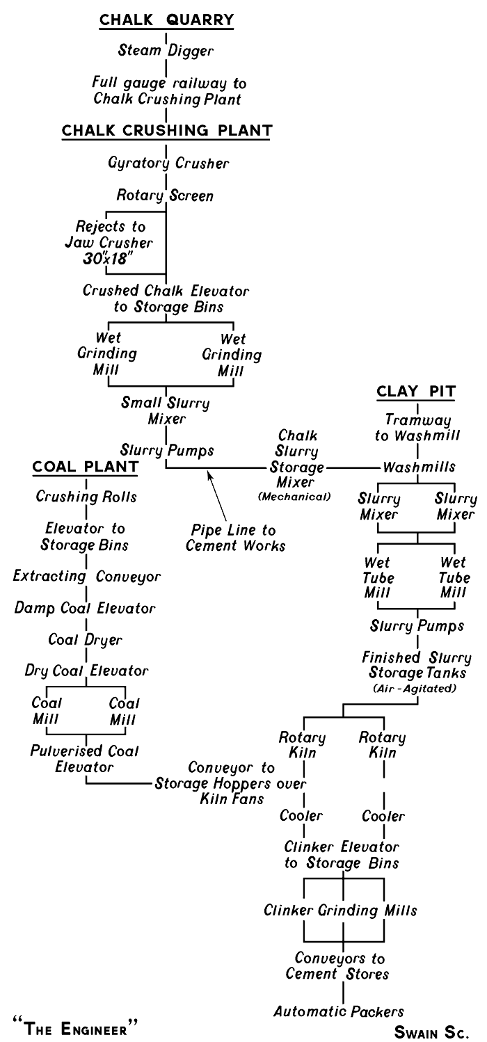
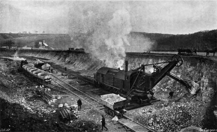
Fig. 5: Bucyrus steam shovel digging chalk
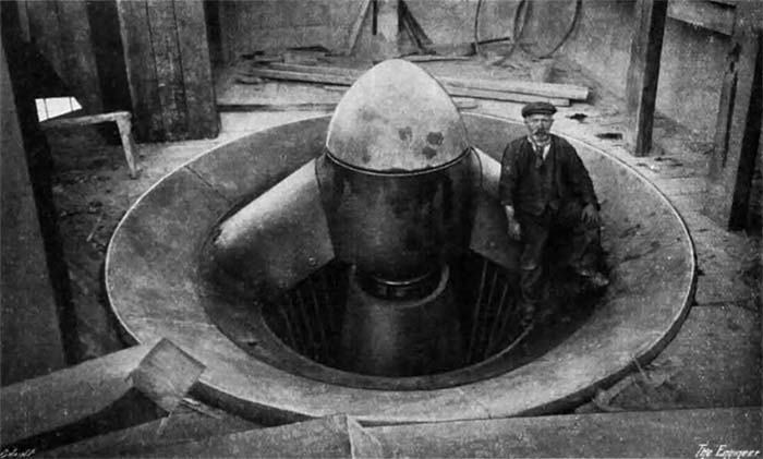
Fig. 7: Gyratory crusher inlet
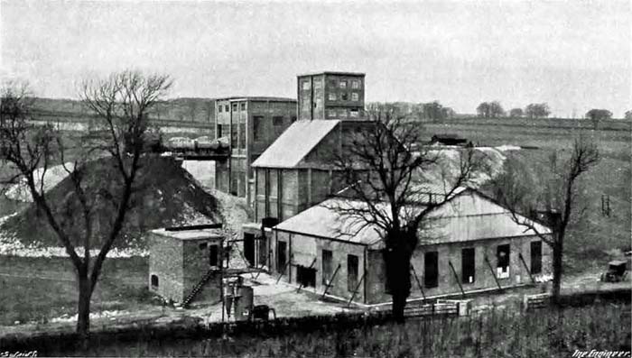
Fig. 1: Rawmill building with crusher and chalk bins behind
THE CHALK QUARRY AND SLURRY PLANT.
It will be convenient in our description of the undertaking—which will be all the more readily understood by the aid of the "Flow sheet" given herewith—to start at the chalk quarry and follow the raw material through its various stages until it becomes finished cement.
The level at which the chalk is at present being excavated is some 135ft. above the ground on which the cement works stand. The excavation is being effected by means of a Bucyrus steam shovel—Fig. 5—which was purchased from the Government after it had been employed in France during the war. It is the only item in the equipment outside the cement works proper which is not of British origin.
Hitherto the shovel has been able to do the excavating without the aid of blasting, though. as we have said, the chalk is exceedingly hard; so hard, in fact, as to resemble stone (Note 10). A lump of it can be lifted and thrown down smartly on a steel rail without being fractured. It was necessary, therefore, to install powerful crushing machinery. The crushers employed are of two types. There is first of all an Edgar Allen No. 9 "Stag" gyratory crusher—Fig. 7—which is an imposing machine weighing some 80 tons, and capable, so we gather, of dealing with about 200 tons of stone per hour when crushing to pass a 4 in. ring. It is driven by a 150 horsepower motor. The chalk is brought from the quarry to the chalk crushing and grinding mill house—Fig. 1—on 7-ton side-tip wagons running on a standard gauge line and drawn by a steam locomotive—Fig. 6 (Note 11).
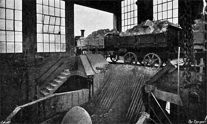
Fig. 6: Chalk wagons for tipping into the gyratory crusher
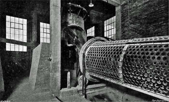
Fig. 8: Rotary screen
We observed three truck loads of chalk tipped rapidly one after another into the hopper of the crusher so that there must have been at least 20 tons in the hopper at once (Note 12). Some of the blocks of the material were as large as 2 ft. cubes. The discharge from the crusher passes by gravity into a rotary screen with 3 in. openings—Fig. 8.
The tailings are comparatively few, and what there are descend by gravity into the hopper of a 30 in. by 18 in. "Stag" jaw crusher, the discharge from which falls into the boot of an elevator, where it meets the material which has passed through the holes of the screen. The elevator, which works almost vertically and at no less than 80 ft. centres, and consists of an endless rubber band to which are attached a series of buckets, has a capacity of about 150 tons per hour. By it the crushed chalk is lifted into a large reinforced concrete silo which is designed to hold about 3000 tons. The silo, which is rectangular in plan (Note 13), is arranged immediately over the feed ends of three—at present only two are fixed—combination tube mills. The latter are 32ft. long by 6ft. in diameter, and they are divided internally into three compartments, two of which are charged with forged steel balls and the third with flint pebbles (Note 14). The compartments are separated from each other by diaphragms of special design. The crushed chalk descending from the silo is delivered on to automatic rotary feed tables which pass on to the tube mills exactly the desired quantity of material, the correct amount of water being added at the same time. Water and chalk are fed into a hollow trunnion (Note 15) at the driving ends of the mills, and the ground slurry is passed out through a diaphragm at the far end of the tube. There is no particular novelty in the mills, which are of quite usual type. Each mill is driven by gearing from a countershaft which is connected by means of a flexible coupling to a set of totally enclosed spur reduction gear, which, in turn, is similarly connected to a 300 horsepower motor. The motors are partitioned from the crushers and mills so that they are protected from dust and dirt. A drawing showing the arrangement of the chalk grinding plant is given in Fig. 2, while views of the interior of the grinding house are given in Figs. 3 and 4.

Fig. 3: Rawmills and slurry pump
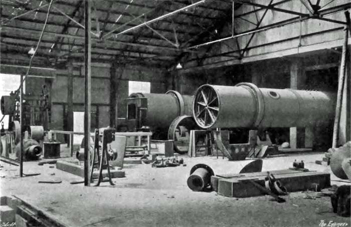
Fig. 4: Rawmills under construction
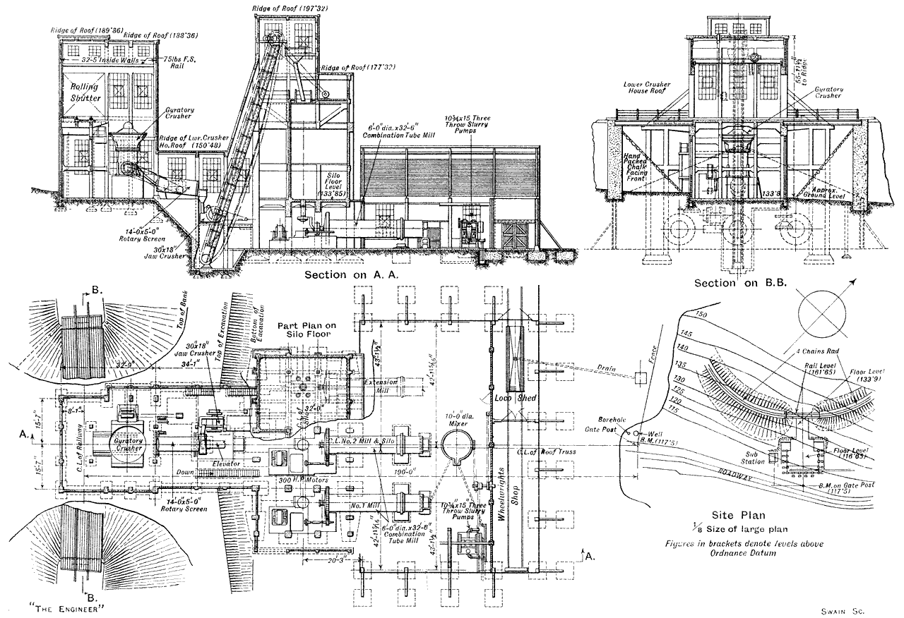
Fig. 2: Rawmill and crusher layout
The chalk is so finely ground in the tube mills that if it were dried and lightly powdered (Note 16) there would not be a residue of more than 10 per cent. on a 180 x 180 mesh sieve. The slurry as delivered from the mills flows into a collecting tank formed below the floor of the mill room and furnished with a motor-driven stirrer. In order to pump it to the works provision is made for two sets of vertical three-throw motor-driven pumps, each capable of dealing with the output from three tube mills, but only one set has as yet been erected. The pumps are designed for a maximum working pressure of 150 lb. per square inch, but since there is a fall of approximately 100ft. between the pump house and the receiving point in the factory, such a pressure as that is not nearly approached in actual practice, and, as a fact, the horsepower required to drive the pumps only averages about 10 (Note 17). The pipe used to convey the slurry is of cast iron, 6 in. in diameter. Its total length is about 2200 yards.
As there is no water available in the immediate neighbourhood of the quarry it was necessary to obtain a supply elsewhere. It was found on going into the matter that, as a certain quantity of water would also be required in the factory, and that as it was known that a plentiful supply could be obtained not far below the surface on the works site, the cheapest plan was to sink a well and install a set of pumps. This course was followed, and the water is now forced by a three-throw ram pump through a main laid in the same trench as the slurry main. It is delivered into a reservoir constructed in the hillside near the mill house at the quarry at an elevation of some 90ft. or so above the floor of that building. Sufficient head is, therefore, provided not only to feed the tube mills but, if necessary, thoroughly to flush the slurry pipe—a contingency which, however, has not yet arisen. It is worthy of note that when the factory is in full operation, with its three units of plant, no less than 4500 tons of chalk will be passed down the pipe each week (Note 18) in addition to the water forming the slurry. The method chosen appears to be the best in every way for conveying this large quantity of material to the works site. Had it not been adopted it would have been impossible to have the works where they are, on a practically level site, alongside the railway and within a short distance of the river.
Before leaving the subject of the quarry and mill house we may explain that the buildings of both crusher and mill houses are of concrete, and that the roof of the latter originally covered a seaplane shed at the aerodrome formed at Brough during the war.
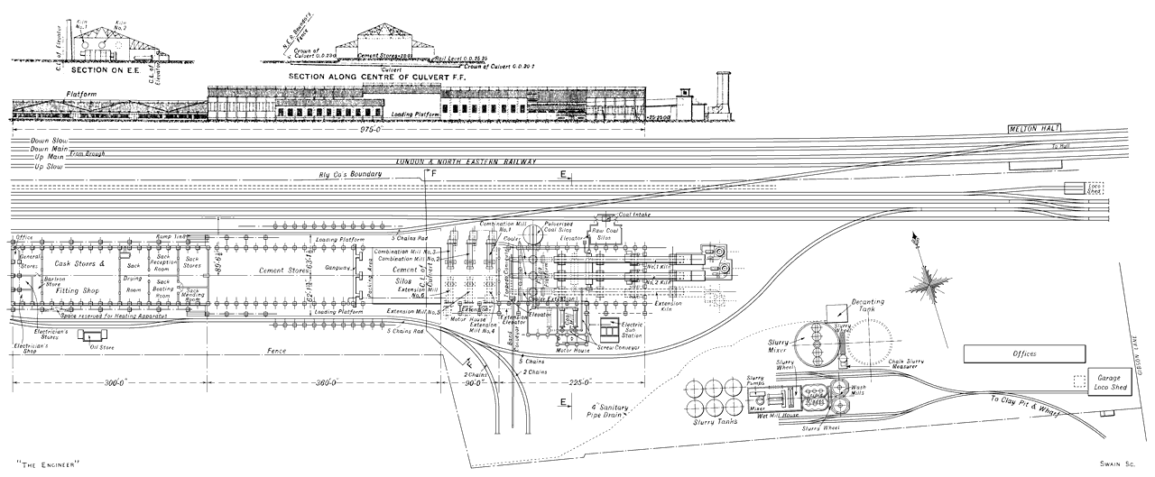
Fig. A0: Cement works layout. View HD image in a new window.
THE SLURRY TANK AND MEASURER AND THE WASH MILLS.
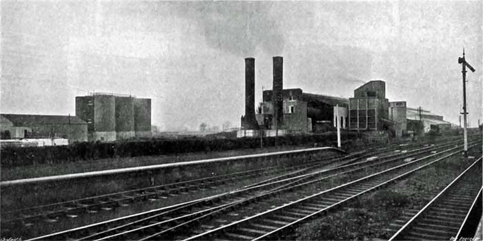
Fig. 9: View of the works from Melton Halt
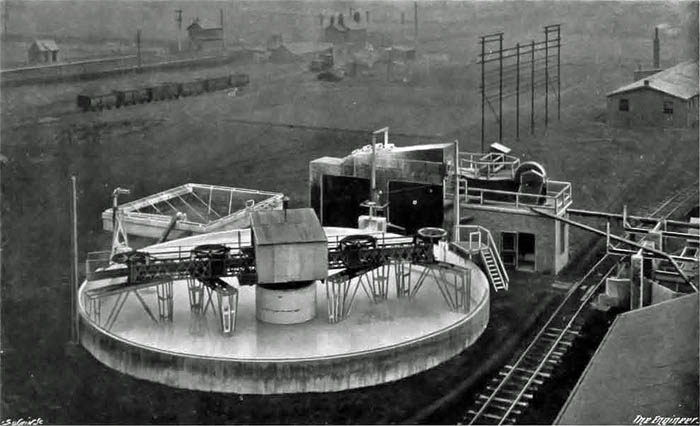
Fig. A1: The chalk slurry storage tank
On arriving at the cement works—a view of which, as seen from the railway, is given in Fig. 9, while a general lay-out plan is shown in Fig. A0—the chalk slurry is delivered into a large circular reinforced concrete tank, 66 ft. in diameter and 11 ft. deep, of which some 7 ft. are below ground level. The tank—see Fig. A1—which is designed to hold about 1500 tons of slurry, is furnished with a stirring device of the sun and planet type. The latter comprises, first of all, a horizontal steel lattice girder, about 66 ft. long, which is supported at the centre of its length on a vertical shaft, constructed in the centre of the tank, on which it can revolve. Depending from the girder are four stirring arms arranged two on one side and two on the other side of the central supporting shaft, corresponding arms on either side being fixed at the same radius so that they balance one another. All these stirring arms, which reach down very nearly to the bottom of the tank, are revolved by means of gearing driven by a 25 horsepower electric motor fixed on a platform attached to the lattice girder, the necessary current being obtained from wires stretched across the top of the tank. The reaction between the revolving stirring arms and the slurry causes the slow revolution of the lattice girder so that, not only do the stirrers themselves revolve, but they are taken slowly round and round in the tank, the result, being that the whole body of the slurry in the tank is being continually agitated and the solid matter contained in it prevented from sinking to the bottom. The bottom of the slurry tank is connected to a sump into which dips the lower rim of a lifting wheel. The latter is about 28ft. in diameter, and it is driven by a 10 horsepower motor. It is made up of light steel strips and sections, and fitted at intervals round its periphery are double elm buckets which scoop up the slurry, lift it and discharge it into a trough just as they travel in turn past the vertical line. This method of lifting the slurry would at first sight appear to be a reversion to an old practice, but it is by no means certain that the slurry wheel in its improved form as made today is not superior to the more recently introduced bucket elevator, bearing in mind its simplicity and comparative freeedom from wear and tear. At any rate, it is employed in the Humber Cement Company's works in several places, and the bucket elevator for slurry not at all.
The trough into which the lifting wheel discharges, delivers the slurry into an automatic measuring machine, driven by a variable-speed motor of 5 horsepower, which passes forward exactly the quantity of slurry required at any given time, the surplus being returned to the sump. From the measuring machine the slurry descends by gravity to one or other of two octagonal wash mills, being made, in the case of either mill, to flow down an inclined shoot in an even film. The wash mills, which measure 20 ft. between opposite faces, are of the usual type, having harrows depending from horizontal arms connected to revolving vertical shafts driven by bevel gearing by a 75 horsepower motor. The clay, which is brought from the workings—of which mention was made above—in side tipping trucks, is taken to one or other of the two mills on either of the branch lines, and is shot by truck-load down the same shoot as that down which the slurry flows. There is a weighbridge over which the trucks pass just before they reach the wash mills, but at the time of our visit the weighbridge belonging to the one mill which was in operation, was not being used. The men, as is often the case in cement mills, have by practice become so expert in judging when more clay is required, that, as a general thing, no weighing is done (Note 19). If, as the result of analysis the slurry is found to need either more clay or more chalk, the men in charge of the clay shoots are immediately informed, and they make the necessary adjustments, but it is wonderful how near to the correct mixture the slurry is kept.
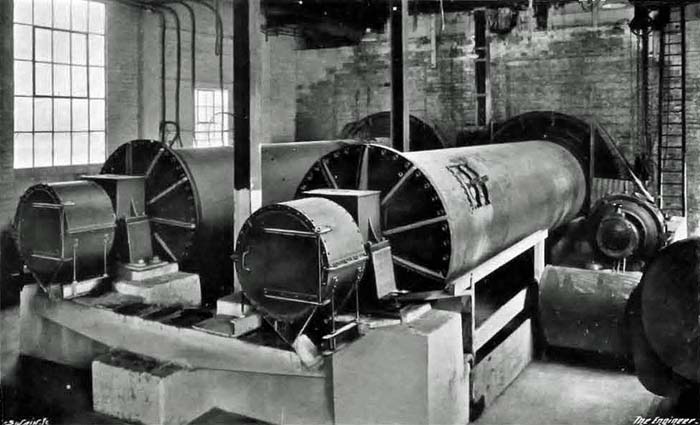
Fig. A3: The finished slurry tube mills
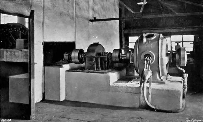
Fig. A4: Tube mills drive motors
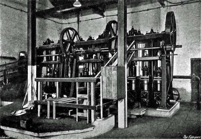
Fig. 10: The finished slurry pumps
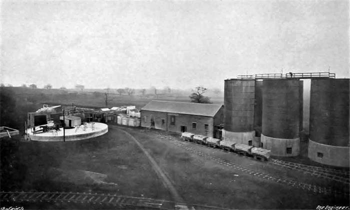
Fig. A2: Slurry storage silos
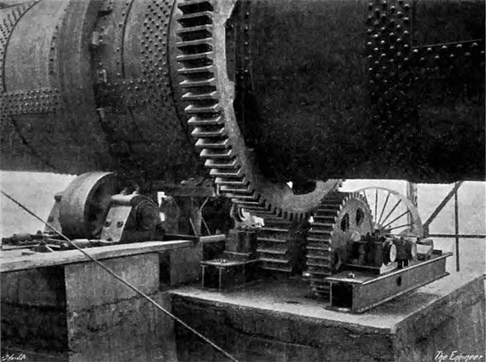
Fig. 11: Kiln 2 drive
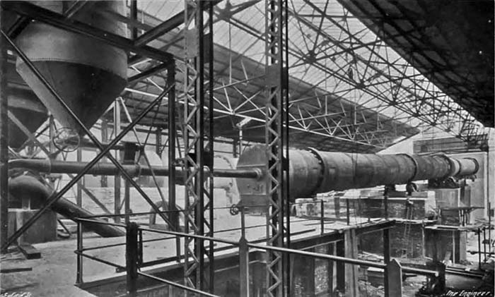
Fig. A5: view from SW across the firing platform to Kiln 2, with kiln 1 in the background. To the right are Kiln 2 fine coal hopper and firing fan.
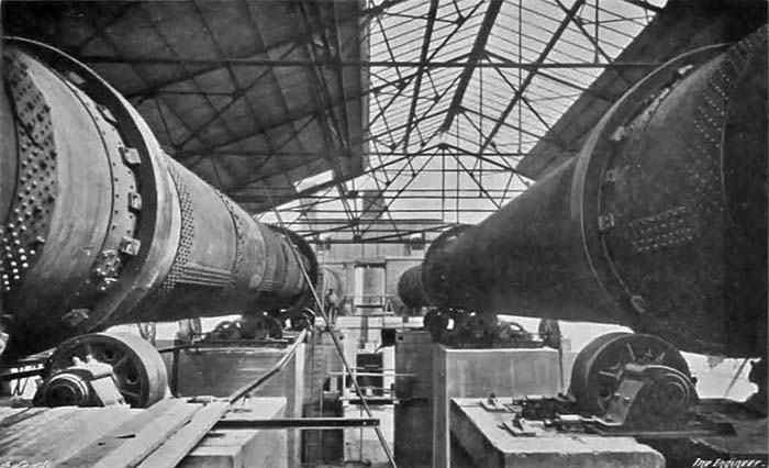
Fig. A6: view between the kilns (under construction) from the firing floor. The kiln drives are mirror images of one another, and the kilns rotated in opposite directions.
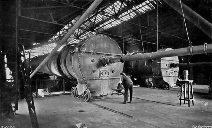
Fig. A7: view of Kiln 1 apparently operating.
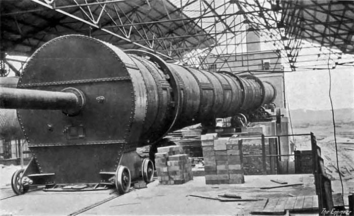
Fig. A8: view of Kiln 2 from the firing floor, apparently before installing brickwork. Kiln 2 lies along the centre line of the kiln house, leaving room for a third kiln to the right.
After passing through the straining gratings of the wash mills the slurry flows into the sump of another lifting wheel, the discharge from which is into either of two reinforced concrete triple mixers (Note 20). Each of the latter measures 40ft. long by 20ft. wide by 10ft. deep, and each is provided with three sets of revolving stirring arms driven in similar manner to, but at a much slower rate than those in the wash mills, by a 20 horsepower motor. The two mixers are designed to hold about a full day's supply of slurry, for it is intended that, under normal circumstances, whereas the grinding plant to which we are about to refer will operate continually day and night, the wash mills will only be worked in the day time. It is from the mixers that samples are being continually taken by the works chemists for analysis, and in them, too, any adjustments in the proportion of the ingredients which may be found necessary are made, the requisite arrangements for the purpose being provided.
THE SLURRY-GRINDING TUBE MILLS.
From a sump connected to both mixers, but separated from them by valves so that the supply may be from one or other or both mixers as desired, the slurry is lifted by another wheel to shoots leading to two Edgar Allen "Stag" tube mills—see Fig. A3—with the construction of which our readers are familiar. They each measure 20ft. by 5ft. in diameter, and they are each driven through gearing by a 75 horsepower motor. In them the slurry is so finely ground that, when dried and pulverised, 95 per cent. of it will pass through a standard testing sieve having 180 holes to the lineal inch. The discharge from the tube mills is into a small receiving tank which is furnished with motor-driven stirring arms, and which forms the sump of the slurry pumps—Fig. 10. Of the latter there are three, all of them being driven through gearing by one 50 horsepower motor, and each being of the vertical three-throw ram type with rams 10¾ in. in diameter by 15 in. stroke. One of these pumps delivers slurry to the feeding platform of the rotary kilns; another can lift and discharge it into a set of air-mixing storage silos situated nearby, while the pipe connections of the third are such that it can perform either of these duties so that it acts as a stand-by for both the other sets.
THE SLURRY STORAGE SILOS.
The provision of a large storage of prepared slurry ready to be fed into the kilns is nowadays looked upon as a necessity (Note 21). It not only aids the chemist in getting his mixture correct, but it makes it certain that the feed to the kilns is not curtailed even though there should be a breakdown of the grinding and mixing plant, or the stoppage of the supplies of raw material by reason of bad weather or from other causes. The storage capacity provided at the works of the Humber Company is sufficient to make about 1600 tons of clinker, or enough to keep both kilns in operation for about 4½ days. The equipment comprises six large riveted steel tanks or silos, each 50ft. high from ground level and 23ft. in diameter—see Fig. A2.
The tanks are on concrete bases in two lines of three each, in a position adjacent to the pump house. It is not, of course, possible to store mixed slurry in a tank or other receptacle without keeping it agitated. The slurry in the silos under consideration is kept agitated by means of compressed air, a method of stirring up cement slurry which has been adopted to a considerable extent in modern plants on the Continent, though the number of installations in this country in which the method has been adopted is comparatively small. Many advantages are claimed for it, especially in connection with medium sized and large factories. For example, it does away with large horizontal mixing tanks containing mechanically-driven stirrers, which take up a lot of room, are costly to build and entail an appreciable amount of expense in repairs. Air mixing is, furthermore, claimed to result in a valuable saving of power, for, whereas it is necessary to keep the stirring arms of mechanically-operated mixing tanks almost continuously at work night and day, it is sufficient for an air mixing tank to be blown for short periods at intervals. The pressure air for the Humber Company's silos is obtained by means of a motor-driven air compressor supplied by Broom and Wade, of High Wycombe, the pressure employed being about 25 lb. per square inch, and the horsepower of the motor 50. The plant is housed in the building which contains the slurry pumps, and where, it may be added, is also the pump employed for lifting the well water to the chalk quarry.
THE ROTARY KILNS.
When the works are fully equipped as designed there will be three rotary kilns, but, at the moment, only two are in position. Each of them is 200ft. long and 9ft. in diameter, and it is noteworthy that they are parallel from end to end and are not enlarged in diameter in the region of the clinkering zone. At the time when kilns with enlarged firing zones were introduced, it was claimed for them that they possessed many advantages over kilns of the same diameter from end to end, but there are many who assert that any advantages which they may possess are more than counterbalanced by disadvantages. It is to be presumed that Messrs. Maxted and Knott share this opinion; it is, at any rate, certain that Edgar Allen and Co., while they are prepared to, and actually do, manufacture both types of kiln, express a decided preference for the parallel kiln except under special circumstances. It is, moreover, generally admitted that, from the point of view of mechanical design, the parallel kiln has much to recommend it, and that an enlarged zone presents difficulties in the fixing and upkeep of the firebrick lining. This by the way; the fact remains that the kilns under consideration are of the parallel type (Note 22). The external tube is in each case composed of twenty rings of heavy-rolled steel plates riveted together, and it is carried on four heavy cast steel tires—one near each end and the others equally spaced between them—each tire being supported on two steel rollers, which latter are mounted on forged steel spindles running in adjustable gun-metal bearings. Following accepted custom these tires are not riveted or bolted to the shell, but are supported on cast steel chairs—themselves riveted to the shell—in such a way as to allow the kiln to expand or warp slightly without distorting them, the insides of the tires being machined so as to fit loosely on the chairs. Each kiln is also provided, near the third tire front the firing end, with a large toothed wheel which is attached to the shell by means of tangential steel plates, so as to give flexibility and to allow for expansion and distortion.
The kiln is driven by means of a variable speed "cascade" 50-70 horsepower motor through a train of machine-cut steel reduction gearing, the pinion on the final spindle of which meshes with the toothed driving wheel attached to the shell—Fig. 11. The controllers for starting and varying the speed of the kilns are arranged on the firing platform. At the time of our visit the kilns were revolving at the rate of one turn in about 2¼ minutes, the output of clinker from the two averaging at the time rather over 14 tons per hour (Note 23). The firing hood is of Messrs. Edgar Allen's standard portable type, and is furnished with the usual firing nozzle, clinker discharge connections, &c. The inclination of the kilns is 1 in 20, and the lining employed on the hotter portions is made of "Adamantine" bricks supplied by C. Davison and Co., Limited. of Chester. Various views of the kilns are given in Figs. A5-A8.
THE SLURRY FEEDING MECHANISM.
The method of feeding the slurry into the kilns is as follows:—The slurry is pumped up to a covered platform constructed above the tops of the flue chambers at the upper end of each kiln, the lift from pump floor level being about 45ft. The pumps are arranged always to raise more slurry than is actually required, and they deliver at present into two automatic feed tanks in which the level of the liquid is always maintained constant, the excess slurry flowing back to the storage plant. In each automatic feeding tank is a horizontal revolving spindle, driven by a motor, the speed of which can be controlled from the firing platform. The spindle is fitted with four equally-spaced hollow arms, the outer ends of which are of scoop form. As the level of the slurry in the feed tank is kept constant, as just explained, the scoops, which dip a certain distance below the level of the slurry, pick up a fixed quantity at each revolution and deliver it into a trough, which discharges into the feed spout leading into the top of the rotary kiln. It is clear, therefore, that since the operator has control of the motors he can very accurately gauge the quantity of slurry being fed into the kiln to meet any variations in the firing or other conditions. We may add that there is also a tell-tale device on the firing platform so that it is always known whether the feeding arrangements are operating satisfactorily or not. Each automatic device has an arm fitted to its spindle which actuates a revolution counter, so that as the quantity of slurry delivered per revolution of the spindle remains constant, it is an easy matter to ascertain the total quantity passed through to the kiln in a given time.
THE FLUE DUST-ARRESTING CHAMBERS.
Before passing on to consider the coal handling, drying and grinding plant and the final processes of manufacture, we return for a moment to the kilns. As has already been explained, the products of combustion as they leave the kiln enter flue chambers, on the top of which is the feeding platform. These flue chambers are of specially large dimensions, with the result that, apparently, but a comparatively small quantity of dust is discharged into the atmosphere, the large majority of it being trapped in the flue chambers. Carefully examining the vegetation in the vicinity of the works, we found it barely possible to observe any evidences of that dust deposition on the foliage which is such an unsightly disfigurement in the neighbourhood of so many cement works. In a field of swedes, beginning within a 100 yards of the works site and stretching away for some hundreds of yards, the leaves of the roots showed no observable coating of dust, but appeared to be perfectly clean. Incidentally, of course, the absence of deposit on the surrounding country means less loss, for much of the dust projected into the air from cement works possesses some value, and though at the present time the Humber Cement Company is taking no steps to treat the dust which is periodically cleared out from the flue chambers, but is using it to raise the levels of certain parts of its site, we understand that it proposes to take up the matter of otherwise using this dust at the first opportunity (Note 24).
THE INDUCED DRAUGHT FANS.
A somewhat unusual feature of the combustion gases discharge arrangements, which is, we believe, unique so far as the cement works in this country are concerned, is the adoption of induced draught (Note 25). A suction fan is arranged in the outlet of each flue chamber, and it delivers the gases, which it extracts, into the base of the chimney. The reason for taking this step was that, because the works are not very far from some high-class residential property and for other reasons, it was not considered desirable to have the chimneys more than 75ft. high. The fans, which are of the propeller type, 5ft. 2in. in diameter, are driven through silent chain gearing by variable speed motors of 30 horsepower. We noticed that the temperature of the gases reaching the fans was about 615 deg. Fah. at the time of our visit. The chimneys, which are of riveted steel plate, are 8 ft. in diameter, and are lined throughout with brickwork.
THE COAL HANDLING, DRYING AND GRINDING PLANT.
The kilns are fired with powdered coal, and the pulverising is done on the site. The arrangements as we saw them were not quite as they now exist, but we propose to describe them in their final state and to indicate in what manner the equipment we saw differed from it. The coal plant was designed to utilise run-of-mine or slack coal, which will be brought on to the site in standard gauge drop bottom wagons, which will discharge it into a receiving hopper constructed immediately below the railway siding. From the hopper the coal will pass through a set of crushers designed to deal with about 30 tons per hour, reducing the coal to pieces not greater than 1 in. cube, the crushed fuel being then lifted by an inclined bucket elevator and delivered into a rectangular reinforced concrete storage bin or silo, which is designed to hold about 1000 tons. At the time of our inspection of the works, although the underground hopper was completed, neither the crushers nor the elevator were fixed, nor was the silo completed, the fact being that the company, when it had got its works into such a state of forwardness that cement could be made without excessive labour costs, decided very wisely to begin manufacture and leave till a more favourable time the completion of non-essential, though by no means useless, portions of the equipment. It took this step when prices of materials were a good deal higher than they now are, and it is now proceeding with the completion works. At first, therefore, temporary expedients were resorted to. The coal, as received, was dumped in heaps at the side of the siding, and was thereafter handled by a travelling jib crane furnished with a bucket grab. We understand, however, that the complete coal handling plant has now been installed and is working satisfactorily.
Arranged underneath the coal storage silos is what is termed a torpedo conveyor, which is a comparatively novel apparatus of the horizontal reciprocating tray type, but is different both in construction and operation from the shaking conveyor. The latter is usually supported from below by means of wood or steel laths, and it receives a comparatively rapid reciprocating or shaking motion from a crank or eccentric driving gear. The torpedo conveyor, on the other hand, is not directly actuated by the driving gear, but is hung by means of links fitted with ball bearings from a framework arranged vertically over it. This framework, which runs on rollers, is given, by means of a revolving cranked axle, a slow reciprocating movement of about 60 strokes per minute, and, as it moves forward, it takes with it the depending tray on to which the coal is delivered. Just before the end of the forward stroke is reached, an air brake—which takes the form of a pneumatic cylinder, the rear end of which is fixed, while the front end of its piston-rod is attached to the underside of the depending tray—comes into action, with the result that, though the forward progress of the tray itself is checked, the coal continues to travel forward by its own momentum, so that, gradually, coal put on the tray at one end is propelled to the other end of the tray. The length of the conveyor, which was one of the few things in the works which were not made in this country, it having been obtained from France, is 53ft., and eventually it will be fed from six automatic feeders depending from the bottoms of the coal silo. On the occasion of our inspection the coal was being dumped on the conveyor at one end from wheel barrows, for, as a trial was in progress, it was necessary to ascertain the weight of the fuel consumed. Notwithstanding the fact that the coal was being shot on to the conveyor in heaps, the action of the apparatus was such that by the time the end of the travel was reached the heaps had got so completely levelled out that the delivery was in a quite even stream. The apparatus works gently and with practically no jar, so that it does not require heavy foundations. We understand that it can even be employed for conveying such impalpable material as ground cement without the necessity of providing a covering because no appreciable quantity of dust is produced.
The delivery from the conveyor, which, it may be explained, is at ground level, is into the boot of a vertical steel-encased elevator of about 65ft. centres, which lifts the coal and delivers it into a receiving hopper over a rotary dryer which is driven by a 10 horsepower motor. Eventually there will be two dryers, but at present only one has been installed, and it is capable of dealing with sufficient coal for the two rotary kilns. The dryer is a riveted steel-plate cylinder, 50ft. long and 5ft. in diameter, provided with tires carried on rollers and revolved in the same manner as are the kilns. It is encased in brickwork and is slightly inclined to the horizontal, so that coal fed in at the top tends to make its way to the lower end. The heat is applied by means of a separate coal-fired furnace, the hot gases being first passed all round the outside of the cylinder and then back inside. The cylinder is furnished inside with ribs which lift the coal and let it fall through the gases. The gases, after leaving the cylinder, pass to a chimney and no fan is used. The dried coal on being discharged from the cylinder falls into a worm conveyor, by means of which it is taken underground into the coal mill house which, as can be seen from the plan, is an entirely detached building. On reaching it the coal is taken up by an elevator into steel plate hoppers arranged above the grinding mills, which are of the combination tube type, and are of similar construction to those used for grinding the chalk, being fed in the usual way by automatic feed tables. Each mill is driven through gearing by a 150 horsepower motor. Eventually there are to be three mills, but at present only two have been installed, each mill being of such capacity that it will grind sufficient coal to feed one of the rotary kilns to such a fineness that 90 per cent. of the powder will pass through a standard testing sieve having 180 holes per lineal inch (Note 26). The powdered coal as it leaves the grinding mill falls into a conveyor, which delivers it into the boot of a dust-proof elevator which, in its turn, lifts it and delivers it by means of a distributing conveyor into either one or other of three—only two of them were in position when we visited the works—steel-plate hoppers arranged above the kiln firing platform. Each hopper is designed to hold enough powdered coal for six hours' working of one kiln.
Should the elevating equipment lift more coal than is needed, the conveyor, which is prolonged for the purpose, can deliver the surplus to a large reinforced concrete silo, which measures 30ft. in diameter by 41ft. high, which is capable of holding some 300 tons, and which has been erected alongside the firing platform (Note 27). The silo is divided into four compartments, and is furnished with automatic extracting screws so that each compartment can be filled and emptied separately. It is not ordinarily intended, of course, to store so much powdered coal as 300 tons, but the reserve capacity has been provided for use in emergency. Normally the silo will only be drawn upon for the supply of fuel for the kilns during weekends when the coal grinding plant is shut down. The conveyors are arranged in such a manner that the powdered coal can be kept in continuous circulation through the silo to prevent any possibility of spontaneous combustion.
The powdered coal from the hoppers over the operators' platform is fed into the kiln in each case by a twin spiral feeder, the delivery from which is into an injector-shaped inlet fitted in the delivery pipe of a high-pressure motor-driven fan, the arrangement being such that the coal falls into the air pipe and is carried forward to the firing nozzle in the hood of the kiln. The spiral feeder is driven by a variable-speed motor, so that the quantity of fuel delivered to the kiln can be regulated as desired. The fans draw their supply of air through the coolers by means of suction pipes taken from the chambers connecting the outlets of the kilns and the inlets of the coolers. This arrangement, of course, serves the double purpose of cooling the clinker, and of assisting the combustion, thereby saving fuel by using preheated air in the coal blast pipe. The whole equipment is standard practice, and does not call for any special comment.
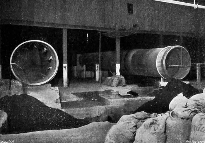
Fig. 13: Rotary coolers delivering into pits
CLINKER COOLING AND GRINDING.
The burnt clinker coming from the kilns falls by gravity to rotary coolers, Fig. 13. There will, eventually, be three coolers, one to each kiln, but at present, of course, there are only two. Each is 6 ft. in diameter and 60 ft. long, and is mounted and revolved in exactly the same manner as are the kilns. In the case of the Humber Company's plant the site and conditions are such that it has been possible—and was actually preferable—to place them in a line with the kilns and with their delivery ends facing in the same direction as the delivery ends of the kilns (Note 28). In this way the direction of progress of raw materials is practically continuous from the point where the chalk and clay enter the factory until the burnt clinker falls from the coolers. As a matter of fact, the process is continued, as will be shown later, until the cement is actually bagged for dispatch, the aims of the designers—with a view to saving labour and working costs—having been for the raw materials to enter the factory at one end of the site and the finished cement to leave it at the other end without having to be taken back on its tracks.
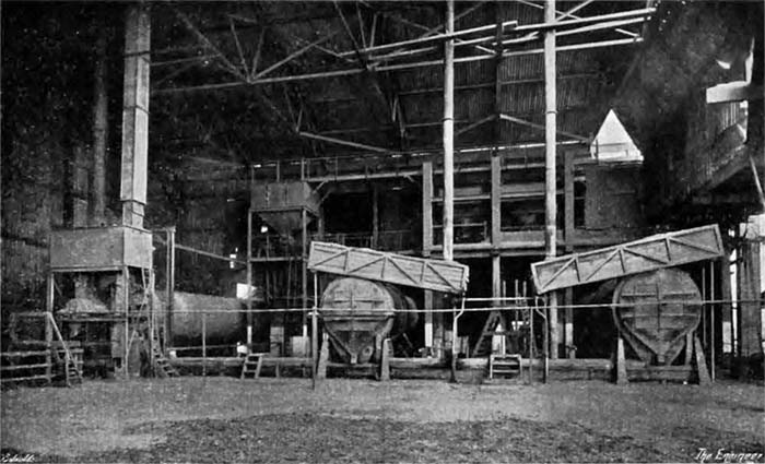
Fig. 12: Finish mills
The coolers are provided internally with steel scoops, which lift the clinker as the cylinder revolves and drop it in cascades through the stream of air which is continuously flowing through the tube. Just before the clinker issues from the cooler it is sprayed by a small jet of water. When the works are completely equipped, the clinker, as it issues from the coolers, will fall on to a torpedo conveyor of similar construction to that which has already been described in connection with the coal plant. This conveyor will deliver it into the boot of a continuous bucket elevator, having a capacity of some 30 tons per hour, which will discharge into another torpedo conveyor, which will be taken over reinforced concrete silos constructed over the cement grinding mills and extended so as, if necessary, to deliver the clinker on to a bulk storage ground. At present, however, these mechanical arrangements have not been installed and the clinker simply falls front the coolers into brick-lined pits, from which it is lifted by means of a jib crane provided with a bucket grab, which in turn discharges it into small tip wagons, the latter being pushed, one by one, on to a weighbridge before receiving its load. The wagons or trucks are then run on a narrow gauge line on a raised staging, one branch of the line extending to just above the hoppers of the grinding mills, and the other over the storage ground. At present the gypsum for regulating the setting time of the cement is added by hand, but when the necessary plant is in position it will be dealt with in the following manner. The mineral arriving by rail in lumps will be fed to a small jaw crusher, and will then be lifted by an elevator to a steel hopper having three compartments. Under each compartment will be fixed a small rotary table feeder, the discharge of which can be accurately adjusted. The delivery will be on to the feed tables for the cement grinders. As much as 60 tons of gypsum per week will have to be handled when the factory is in full operation.
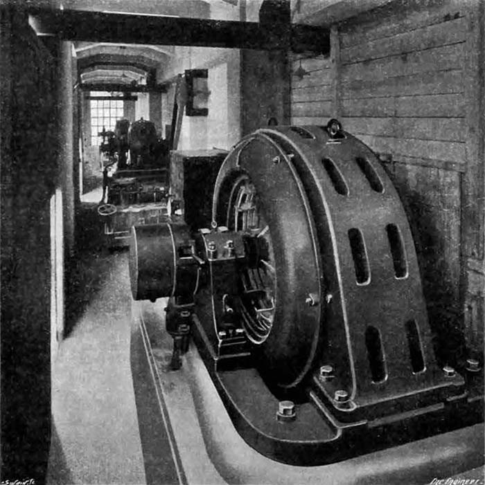
Fig. 14: Finish mill drive motor annex
The clinker is ground in three Edgar Allen "Stag" combination tube mills, which are practically identical with those already described (Note 29), and one of them is driven by a 500 horsepower motor, while the other two, which are smaller, are each designed to grind from 8 to 10 tons of cement per hour to a fineness considerably greater than that stipulated in the British standard specification. As a matter of fact, we understood that at the time of our visit the fineness was such that only 5 per cent. remained on a standard 180 by 180 mesh sieve. Each of the two smaller mills is driven through a train of gearing by a 400 horse power motor. The clinker from the silos is extracted by automatic rotary tables of the usual type and is fed into the mills by means of special spiral feeders. Views of the clinker grinders and of their driving motors are given in Figs. 12 and 14.
THE CEMENT STORAGE AND DISPATCH.
The grinding mills are in a direct line with the kilns and the coolers, and the ground cement discharged from them is again taken forward in a straight line by means of an elevator and conveyors. A concrete raft foundation for a cement store, which is to have a capacity of several thousand tons, is already in position, and although the building is not yet erected, we may say that the silos which it will support will be arranged in two rows, beneath each of which will travel a special portable extractor. It will be possible to attach these portable extractors, which will be driven by small electric motors, to any one of numerous hopper mouths beneath the various compartments of the silos. They will then take the cement from the silo and deliver it into a long spiral conveyor running the full length of the building between the two lines of silos. The advantage claimed for this arrangement of plant is that the silos can be divided into a considerable number of compartments without having to incur the capital expenditure involved in installing a similar number of extractors. It will thus be possible to store different batches of cement in separate compartments.
For the time being the cement is being stored in bulk in a building constructed for the most part out of material which was used during the war for seaplane sheds at the naval aerodrome at Brough. The cement is brought into the building at a height of some 20 ft. or so, and is taken down along its centre, depending spouts being arranged at intervals in its length so that the cement can be delivered up into sections by means of wooden partitions. There are also longitudinal partitions so as to leave a gangway down each side of the central space. Below the floor in each gangway is a spiral conveyor, and each division of the floor is in communication with the conveyors on each side by means of shoots. When it is required to draw upon any particular division its shoots are opened. A certain amount of the cement will then pass into the conveyors by gravity, and the rest is helped on its way or actually shovelled towards the shoots by men. The conveyors both deliver at the same end of the building, and there are two elevators which lift the cement into hoppers over two weighing and sacking machines, one on each side of the building, which has a railway siding and platform on each side of it. The weighing and sacking machines were supplied by the Bates Valve Bag Company, of Chicago. With them the mouths of the bags are tied before being filled, and the filling is carried out through an opening in the bottom of the bag, which is so formed that it is self-closing when the weight of the cement comes on it. By these means the cement is weighed and the bags are filled automatically. For the time being, when the filling process is completed the bags are wheeled away on hand barrows into covered railway vans or trucks drawn up beside the platform. Eventually, however, there is also to be a travelling band by means of which the bags ran be transported to the filled bag store. We understand that one man can, without difficulty, operate a sack-filling machine dealing with 30 tons per hour.
THE SACK DRYING, CLEANING AND MENDING PLANT.
A necessary adjunct to the use of sacks is a sack drying, cleaning and mending plant. Sacks returned to the factory are always dirty and are frequently wet and torn. They must be dried before anything can be done witht hem. The drying plant is very similar to that used in some laundries. There is a heated chamber into and out of which "horses" on which the sacks are hung can be pushed and pulled by hand, the "horses", of course, being furnished with wheels which run on rails. The sacks when dried are placed in an octagonal drum, of the squirrel cage type, which is made to revolve in a chamber from which the dust is exhausted. The cleaning process over, the sacks are taken to the mending room, which is equipped with a row of power-driven sewing machines, and, when any needed repairs have been effected, they are finally taken to the sack store (Note 30). Provision has been made for the use of casks for the dispatch of cement, and a building set apart for the purpose of making and repairing wooden casks. At the time of our visit, however, only sacks were being used.
THE LABORATORY AND CEMENT ANALYSIS.
The factory is, of course, provided with an excellently equipped laboratory—a sine qua non in a modern cement works. We have been furnished by the company with some figures regarding the strength of briquettes made with cement produced in the works, which we reproduce below. These figures have, as will be observed, been recorded by three firms well known for their tests in connection with cement and were arrived at quite independently.
Attention may be drawn to the results of the twenty-eight days' sand tests, the average for which, it will be noticed, practically complies with the British standard specification for neat cement.
We mentioned earlier in this article that during our visit a trial run of the kilns was being carried out, and by the courtesy of the consulting engineers, we are enabled to state that the output of the kilns was so much above the guarantee that the makers were entitled to a large bonus, and that the coal consumption was almost exactly the guaranteed percentage.
CONCLUSION.
With regard to the works as a whole, they struck us as being specially well arranged for the cheap manufacture of cement, and even though, for the moment, all the labour-aiding devices which are proposed have not been installed, we should judge the working costs must compare very favourably with those of works using similar raw materials. This opinion would seem to be borne out by the small number of hands employed, to which feature we referred to (sic) in the course of the article (Note 31).
Independent Tests of Humber Brand of Humber Portland Cement
| Test | Requirements of the BS Specification | H Faija & Co | R H H Stanger | Davey & Bell | |||
|---|---|---|---|---|---|---|---|
| Delivery | Grinding | Delivery | Grinding | Delivery | Grinding | ||
| Tensile 7 days: psi | |||||||
| Neat cement | 450 min | 846 | 850 | 847 | 840 | 746 | 742 |
| 3 sand : 1 cement | 200 min | 430 | 438 | 383 | 381 | 423 | 431 |
| MPa (Note 32) | 17 | 17 | 14 | 14 | 16 | 17 | |
| Tensile 28 days: psi | |||||||
| Neat cement | 530 min | 917 | 919 | 960 | 948 | 862 | 870 |
| 3 sand : 1 cement | 250 min | 537 | 532 | 475 | 469 | 579 | 586 |
| MPa (Note 32) | 28 | 27 | 23 | 23 | 31 | 31 | |
| Chatelier test: mm | 10 max | 0.8 | 0.9 | 1.15 | 1.1 | 0.7 | 0.6 |
| Setting time: minutes | |||||||
| Initial | 97 | 91 | 106 | 119 | 118 | 112 | |
| Final | 223 | 190 | 214 | 227 | 279 | 277 | |