Arlesey

Arlesey Eddystone Brand cement Logo
Arlesey Lime and Portland Cement Company Eddystone Brand.

Location:

Clinker manufacture operational: 1883 - 1932

Approximate total clinker production: 1.76 million tonnes

Raw materials:

See also an in-depth article on The Chilterns.

Ownership:

The plant was built to the north of the pre-existing lime and brick plant, on the site of the worked-out brickfield. The 1886 Engineer article implies that Portland cement manufacture had been subject to “costly and fruitless attempts” at the site before the plant described was launched. A previous plant called the "Hydraulic Lime and Cement Works" was put up for sale in October 1875. This had two 25-ton wet process bottle kilns along with three wash backs and drying flats, evidently using chalk marl alone. Evidently only hydraulic lime had been produced. When the new plant started, chalk and gault clay were used, the clay being already available from the much more substantial brickworks next door. The plant as first designed exemplifies the great simplicity and compactness of the “off-the-peg” cement plant of the 1880s. Read the Engineer article.. The plant started up with a set of six Johnson chamber kilns, capacity 120 t/week. In 1887 four locally-designed double-deck chamber kilns were installed, giving 100 t/week. Installed in 1888 was one of the second-generation Ransome rotary kilns which, like the others, failed to operate successfully, although Stokes used it to pilot his own developments in the 1890s. Seven more chamber kilns (210 t/week) were added in 1891. A further block of six (190 t/week) and four Schneider kilns consuming excess slurry dryings (320 t/week) were installed around 1900. This made the total capacity 940 t/week. It became one of only two plants (the other being Vectis) outside the Thames/Medway area comprising APCM in 1900. The installation of the rotary kilns involved the removal of the first block of chamber kilns in 1903. The remaining static kilns continued in commission, although only intermittently used: they were last operated in 1926. The plant was described in detail in the APCM 1924 schedule. All transportation was by road and the Great Northern Railway. Although the raw materials were excellent and the site was strategically good, negotiations to extend the land southward failed and the reserves of high carbonate chalk were insufficient to make an upgrade worth while, so the plant closed with the 1932 downturn. Most of the site is long cleared, and is now partly occupied by a readymix plant, but the second chamber kiln block remained until demolished in 2019. Some foundations are still visible on the unoccupied ground towards the railway. The quarries are flooded.

Power Supply

The original plant was directly driven by two 180 IHP single-expansion steam engines. The rotary kilns and firing system were electrically driven, using two generators each attached to 160 HP double-expansion steam engines, but the rest of the plant remained steam-driven until closure, using two double-expansion engines 220 and 420 IHP.

Rawmills

The original plant had two 18 ft washmills followed by flat stones. Later, the latter were replaced with an edge-runner. The final format used essentially the same washmills, but in series, the second functioning as a screener, with no further processing.

Three rotary kilns were installed:

Kiln A1

Supplier: Ransome
Operated: installed 1888: modified to Stokes design around 1892 - never produced commercially
Process: Wet with separate drying tube
Location: hot end 518977,234998: cold end 518986,234997: totally enclosed. (This location is a “best guess” based upon likely map locations and the photograph.)
Dimensions: 28’0”× 5’0” (metric 8.53 × 1.524)
Rotation (viewed from firing end): anticlockwise
Slope: 1/14 (4.096°)
Speed: ?
Drive: via shaft from steam engine: power draw not known, but probably about 400 W.
Kiln profile: 0×1524: 8534×1524: rollers at 2134, 6401: turning gear at 6096.
Cooler: rotary 38’0”× 2’3” (metric 11.582 × 0.686) beneath firing floor.
Cooler profile: 0×686: 11582×686: tyres at 1829, 7925: turning gear at 2134.
Fuel: Producer gas
Typical Output: 8.6 t/d (calculated 2023 model)
Typical Heat Consumption: 23.5 MJ/kg (calculated 2023 model)


Kiln B1

Supplier: “Pollitt and Wigzell”. This may just be a contractor. They made steam engines. The kilns were identical to those at Swanscombe and so were Fellner & Ziegler (considerably modified).
Operated: 3/1903-1932
Process: Wet
Location: hot end 518981,235110: cold end 519022,235108: totally enclosed.
Dimensions:

Rotation (viewed from firing end): clockwise
Slope: 1/13.8 (4.156°)
Speed: 0.86 rpm
Drive: 30 kW
Kiln profile:

Cooler:

Cooler profile:

Fuel: Coal
Coal Mill: both kilns indirect fired using common coal milling system - Krupp 60 kW tube mill
Exhaust: direct to common stack.
Typical Output: 3/1903-11/1907 39 t/d: 1/1908-4/1913 79 t/d: 6/1913-1925 92 t/d: 1926-1932 103 t/d
Typical Heat Consumption: 3/1903-11/1907 9.2 MJ/kg: 1/1908-4/1913 8.6 MJ/kg: 6/1913-1925 11.0 MJ/kg: 1926-1932 8.20 MJ/kg

Kiln B2

Location: hot end 518981,235104: cold end 519022,235103: totally enclosed.
Dates: 5/1903-11/1907: 1/1908-5/1913: 7/1913-1932 Identical in all other respects to B1.


Sources::

Read the Engineer article.

The following is a transcript of two anonymous articles that appeared in The Engineer, 56, 19/10/1883, p 303; 56, 30/11/1883, p 421 and 62, 8/10/1886, pp 291-2. They are believed to be out of copyright. The 1886 article describes the original plant at Arlesey, which is an example of the "off-the-peg" chamber kiln plant in its simplest form. It also gives a useful close-up on a typical finish mill installation of the time. Note on Imperial units of the time: 1 ton = 1.016047 tonnes: 1 ft = 0.304799 m: 1 in = 25.4 mm: 1 h.p. = 0.7457 kW: 145.037 psi = 1 MPa.

NEW PORTLAND CEMENT WORKS AT ARLESEY.

Arlesey West

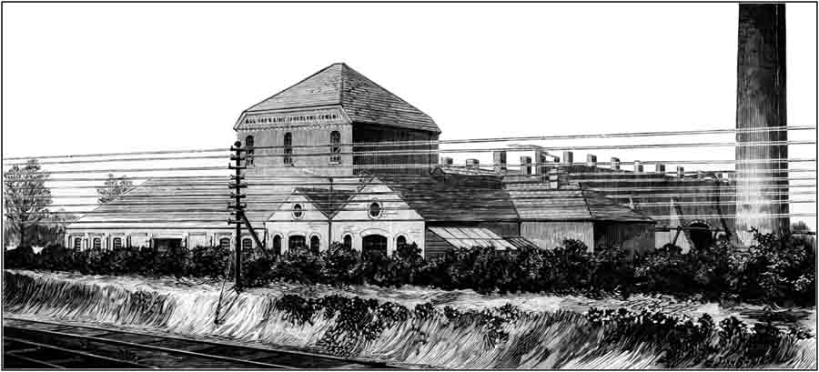
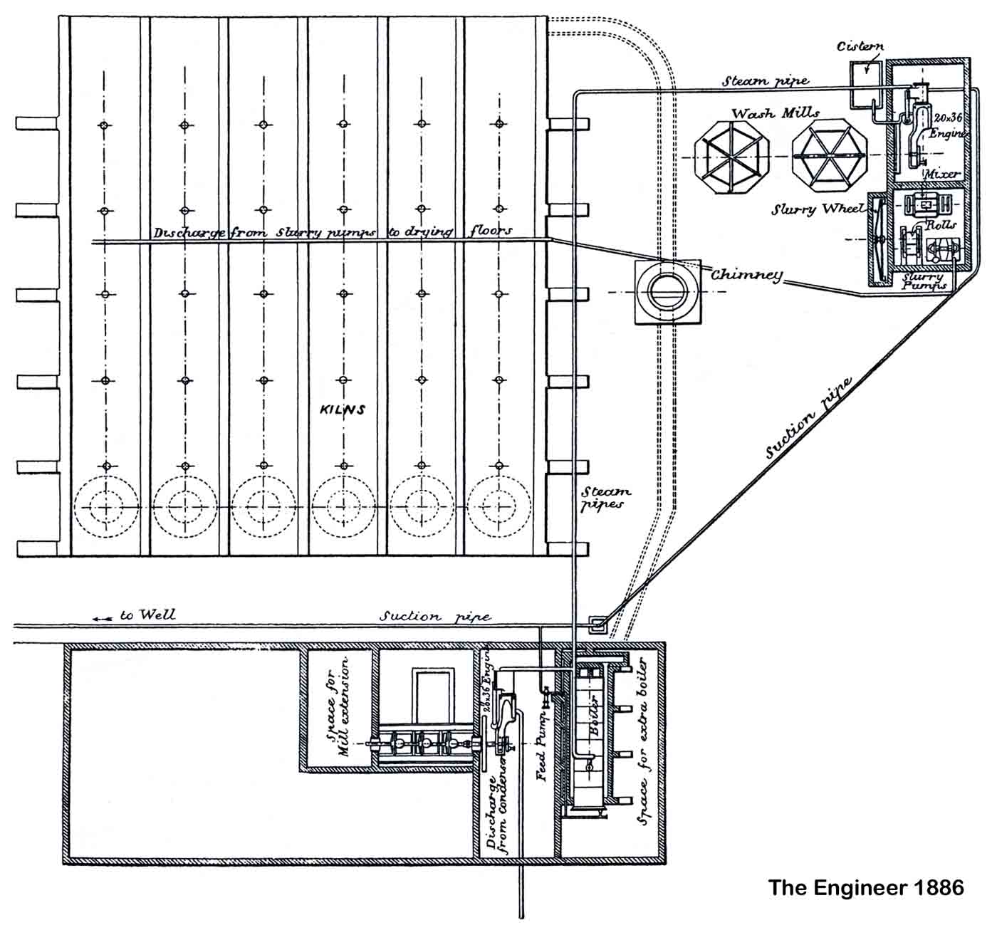
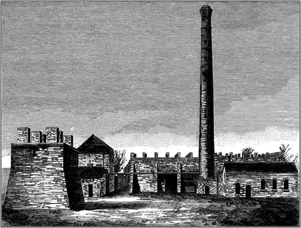
The illustrations show the side nearest to the Great Northern Railway of the Portland Cement Works recently erected at Arlesey Siding, Great Northern Railway, by the Arlesey Lime and Portland Cement Company, and the smaller engraving shows the opposite side (Note 1). A plan of the works is given (below). The whole of the building, machinery, &c., were designed by the Pulsometer Engineering Company (Note 2), which has also manufactured and supplied the machinery. The works are now turning out Portland cement of the highest quality. The machinery already erected consists of two similar horizontal condensing engines 20 in. diameter of cylinder by 36 in. stroke, running at 60 revolutions per minute, fitted with variable expansion gear, and each capable of indicating from 93 to 180 horse-power.

Arlesey South

One of these is used for driving:

  1. the slurry mills, each 18ft. diameter;
  2. the slurry wheel 18 ft. diameter, for raising the slurry, which is driven at slow speed by new differential gear;
  3. a set of special rolls through which all the cement slurry is passed;
  4. the mixer, a new machine for incorporating the slurry;
  5. slurry plunger pumps, 10in. diameter by 16in. stroke, which raise the slurry, after it has passed through mills, rolls, and mixer, to the top of the kilns.

The second engine actuates:

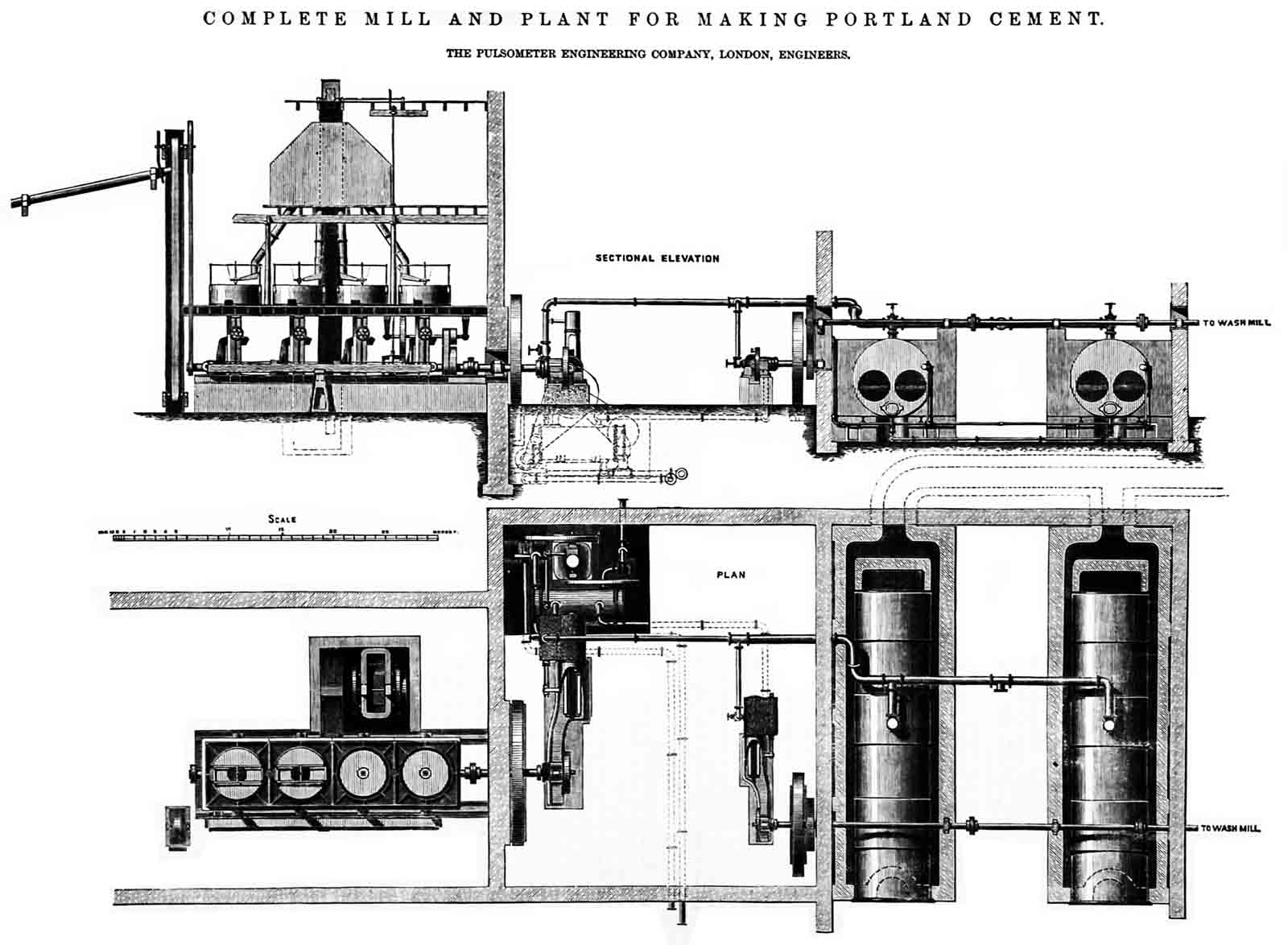
  1. a specially designed crusher which reduces the cement clinkers to pieces about ⅜ in. cube, so as to diminish the work performed by the stones;
  2. the mills, which are of the Pulsometer Engineering Company's self-contained pattern already illustrated in "The Engineer" (see below).

A single Lancashire boiler 7 ft. by 28ft—steel—working at a pressure of 80 lb., furnishes steam for the whole installation. It is fed by a Deane steam pump 5½ in. by 3¾ in. by 10in. stroke. Special interest attaches to these works, costly and fruitless attempts (Note 3) having been made in times past to manufacture Portland Cement from materials on the estate. This is, we believe, the only locality near London in which gault clay and chalk are found together (Note 4). Careful analyses made by Mr. G. M. R. Layton (Note 5), the managing director, proved that these materials were capable of being manufactured into cement of high quality, and the sub-joined tests will show that with care and judgment no materials can be more beneficially employed for the purpose. Average breaking strain after seven days of 100 briquettes of 1½ in. by 1½ in. by Adie's machine, 1020.42 lb. Average of 50 1 in. briquettes, 398 lb (Note 6). The cement is already in far greater demand than can be supplied by the present kiln power, and additional kilns, patented by Mr. Layton (Note 7), are now being erected. The result of the substitution of the special rolls and mixer for the ordinary wet stones has been highly satisfactory (Note 8). The arrangements are specially made with a view to saving labour, and the progress of the material in the cheapest way direct through the works.

Arlesey Plan

Three years earlier (19/10/1883, 56, p 303 and 30/11/1883, 56, p 421), Pulsometer had advertised a similar plant, at another location, in greater detail.

Pulsometer Plant

(To the right is) published a plan and sectional elevation of a Portland cement mill, erected by the Pulsometer Engineering Company, for an output of fifty tons of cement per day. The engravings showed the arrangement of the millstones and clinker breaker (Note 9) and elevator therefrom, the engine-house with two engines and condenser, one engine being coupled direct to the mill shaft, and the other employed in working a shaft for driving wash mills. The elevator from the clinker breaker lifts the broken stuff up to a hopper common to the four pairs of stones, while the ground cement from the stones is carried away by a belt and delivered to an elevator, which raises it to a suitable elevation for storage.

The engine for driving the cement mill is illustrated more clearly by the accompanying perspective, Fig. 2. It is of the horizontal type, with a steam cylinder 21 in. diameter by 36in. stroke, making sixty revolutions per minute. The slide valves are placed one at each end of the cylinder, and separate expansion valves on the back of the main valves. The range of expansion is controlled by means of the governor, which acts upon a rod carrying a block sliding in a slotted link. This link is pivotted upon a pin, and is driven by an eccentric on the crank shaft. The expansion may also be controlled by hand independently of the governor. The crank shaft bearing is in four pieces, having means of adjustment for end wear as well an top and bottom wear. The bearing is 8.5 in. diameter by 17 in. long, and is unusually large. The fly-wheel is 14ft. diameter, and the connecting, piston, and valve rods are of steel.

The cement mills consist of four pairs 4 ft. 6 in. stones, illustrated by the perspective and detail engravings, Figs. 3 to 6 (Note 10). The mill shaft for the first two mills is 8.5 (in) diameter. This shaft is made large enough to drive four more pairs of stones. The gearing is extra strong, being made of cast steel, and is in the ratio of 2.25 to 1; the teeth are 2.75 in. pitch by 6.5 in. broad on the face ; the vertical millstone spindle is 3.5 in. body. An important improvement is the arrangement of stone spindle. This has been adopted at the suggestion of Mr. Shadbolt, of the firm of Coles, Shadbolt, and Co. (Note 11), who devised this improvement and had it at work on his own mills since 1866 with the most satisfactory results, the same bearing being still in use with no detrimental wear. It will be seen that the spindle passes through brass bushes held and made adjustable in a cast iron box, and rests on the movable footstep supported by the lightering bar; the wear of the footstep so troublesome in the usual arrangement is thus avoided, and ample provision made for taking the wear from the side thrust of the spindle. The clinker elevator, which is driven from the mill shaft by means of bevel gearing and vertical spindle, takes the material from the crusher by means of band and buckets, passing over pulleys at the top and bottom. The clinker is raised and falls into the hopper or bin placed on the top floor of the mill; from this bin the four spouts are led which distribute the clinker to each pair of millstones.

The engine for driving the wash mills is similar in every respect to that already described for driving the cement mills, except that it is smaller, having a steam cylinder 15 in. diameter by 30 in. stroke. The crank shaft bearing in 5.5 in in diameter by 11 in. long; the fly-wheel is 12 ft. in diameter. It will be noticed that the wash mill shaft — see the engraving (above) — is above the engine shaft, to which it is geared, and passes over the top of the boilers and on to the wash mills. The wash mill shaft is 5.5 in. diameter, and is geared to the vertical spindle by bevel gearing in the proportion of 4 to 1; teeth, 2.5 in. pitch by 6 in. on face; vertical spindles, 6 in. square. In consequence of these mills being erected near the mouth of a tidal river (Note 12), it was found necessary to use a surface condenser for the condensation of the steam from each engine. It is shown on the general plan — (above) — placed under the floor level, the condenser apparatus requiring to be placed low down to suit the lowest level of the tide. The condenser consists of a cast iron cylinder, having covers and the usual tube plates at each end, and contains 604 brass tubes, 0.75 in. diameter and 7 ft. in length between plates. The tubes are packed by wood ferrules as in an ordinary marine engine condenser.

The pumps consist of a 6 in. centrifugal for circulating the water through the condenser, through the tubes of which it passes twice; and of a vertical air pump. Both pumps are driven by straps from pulleys on the crank shaft of an inverted cylinder engine of 10in. diameter and 18in. stroke. It will be seen thus that the arrangement has many advantages over separate condensers for each engine, a vacuum being obtained in the cylinder of each engine before starting, which is advantageous when starting engines with the heavy machinery employed in cement-making. In the space for the condensing apparatus are also fixed two donkey pumps for feeding either hot or cold water, the feed passing through an economiser on its way to the boiler. The boilers are two in number and are of the usual double-flued or Lancashire type, 7 ft. 3 in. diameter by 30 ft. long; flues, 3 ft. diameter, each flue having Galloway tubes. The boilers are worked to a pressure of 60 lb. per square inch.

The mill is altogether very completely fitted up, and with the machinery and engines described it will be seen that less power is used than is usual for works of the capacity of 50 tons per day.

NOTES

Note 1. Actually the top picture shows the view from the west, and the bottom the view from the south. The building with the pointed roof is the upper storey of the mill house, containing the clinker feed hoppers. The two gable-ended buildings are (left) the engine house and (right) the boiler house. The stack was common to both the kilns and the boiler. The structure in the left foreground of the bottom view is probably a set (perhaps just a pair) of lime kilns.

Note 2. The equipment of the plant consisted largely of high Victorian steel and brass engineering, and the six Johnson chamber kilns are not mentioned. The kilns probably accounted for a very small proportion of the plant's capital cost. There is no suggestion that this section of the plant might be amenable to innovation. The Pulsometer company was founded in 1875 and continued in independent existence until 1961, concerning itself mainly with pumps.

Note 3. These probably consisted of attempts to use the Chalk Marl, un-ground and un-blended, as was also attempted in Cambridgeshire.

Note 4. A belief not informed by any knowledge of geology! Chalk and Gault clay had been used in the Medway Valley (nearer to London) for the previous 20 years. Later the plant abandoned Gault Clay in favour of Chalk Marl.

Note 5. George Layton remained in charge and became a Director of APCM when the plant was taken over in 1900.

Note 6. These are tensile strengths: the 1½" briquettes give 454 psi (3.13 MPa) and the 1" briquettes give 398 psi (2.74 MPa). Assuming these are neat cement tests, the corresponding modern EN 196 compressive strength is 2.9 MPa.

Note 7. These were essentially Michele kilns, which presumably did not have a watertight patent.

Note 8. Both the chalk and the clay were fine-grained with little sand content, and a coarse slurry (provided that it was well mixed) would have been tolerable (although far from ideal).

Note 9. This is a jaw crusher, apparently (from the drawing) around 2 ft square opening. It was fed by hand from skips of clinker unloaded from the kilns. The clinker from chamber kilns was in the form of irregular pumice-like chunks.

Note 10. The mills are in the standard format with a fixed lower stone, and a rotating upper stone suspended on a stirrup attached to the end of the drive shaft, which comes up through the bed of the mill. From the drawing it can be seen that the lower stone could be aligned by use of set screws below, and the vertical position of the shaft, which controlled the clearance between the stones, was provided with a geared-down fine adjustment.

Note 11. This is probably Percy George Shadbolt. Coles, Shadbolt & Co. originally made Roman Cement, and went on to make Portland cement at Waldringfield and Harefield, but neither of these dated from 1866, so the reference is probably to their Roman cement mill at Caledonian Road, London.

Note 12. A fair number of plants began in the period 1880-1883, and many of these were on tidal water, so it is not clear which plant this was, but in view of the reference to Shadbolt, it may refer to an upgrade of Waldringfield, which was on the waterside of the Deben estuary.