William Elijah Benton (1855-1940) was a mining engineer from Walsall. He bought the Springfield Park brickworks in Acton, Middx., and branched out as a lime merchant, setting up a lime plant at Chinnor with five beehive kilns, commencing in 1908. This followed the construction of the Acton-High Wycombe railway in 1903, allowing direct rail communication between the two sites. After WWI, in partnership with his son Norman Molyneux Benton (1885-1968), a cement plant was constructed and started up in 1921. This had the distinction of being the last plant to be commissioned with intermittent kilns, having four, and later seven, Batchelor kilns, at a time when most existing cement plants were demolishing their static kilns. A rotary kiln was finally installed in 1928.
The Chinnor plant was described in two anonymous articles in Cement and Cement Manufacture (I, Dec 1928, pp 93-96 and II, June 1929, pp 171-178), shortly after it had installed its first rotary kiln. These articles are out of copyright. The text and graphics of the latter are identical to those of a pamphlet issued by Edgar Allen in 1929, and the following is sourced from the this.
Values of imperial units (as of 1929) used in the text (alphabetical order): 1 acre = 0.40468424 Ha: 1 ft = 0.30479947 m: 1 gallon = 4.5460756 dm3: 1 HP (horse-power) = 0.7456998 kW: 1 inch = 25.399956 mm: 1 psi (pound-force per square inch) = 6.89478 kPa: 1 ton = 1.01604684 tonne: 1 yard = 0.91439841 m.
A 40,000-Ton a Year Plant
The Chinnor Cement and Lime Company, whose works are situated at Chinnor, eight miles north-west of High Wycombe (where they were established in 1908), have just erected a new rotary kiln plant capable of producing 40,000 tons per annum on a site adjoining the older plant.
The works are situated at the base of the northern slopes of the Chiltern Hills, and comprise 180 acres of land, composed of soft grey chalk which varies in calcium carbonate content between 50 per cent. and 90 per cent., thus supplying all the needs of cement manufacture without the necessity of importing any other raw material except gypsum for slowing the set.
The quarry is immediately alongside the factory, the chalk from it being won with the aid of a steam shovel. The raw material is washed in a 20-ft. washmill, and from there is passed through three further classifying machines whereby the slurry is not allowed to pass to the pumps with more than a 5 per cent. residue on a sieve containing 32,400 meshes to the square inch (Note 1).
The stored slurry is contained in three 600-ton vertical steel tanks, one of which is always supplying the kiln with slurry of the desired composition. The slurry in all three tanks is agitated by compressed air. The kiln slurry-feed is driven by the kiln so as to regulate the supply to the speed of the kiln. The kiln (by Messrs. Edgar Allen & Co., Ltd.) is 185 ft. long including a 20-ft. cooler on the discharge end of the kiln. A shaker conveyor by Messrs. F. L. Smidth & Co., Ltd., carries the clinker to the elevators and so to the mills.
The cement mill is divided into four compartments, and is capable of grinding 7 tons per hour to a residue of rather less than 5 per cent. on a 180 sieve, or finer when making rapid-hardening Portland cement.
The coal is dried in a rotary drier and ground in the standard type of combination mill. The older method of coal preparation was deliberately chosen to ensure an evenly dried and ground fuel to the kiln.
The cement is stored in silos of a capacity of 5,000 tons. There is a packing-house capable of storing 200 tons of cement packed in sacks, two siding connections with the G.W. Railway Co., and an ample lorry park.
All the auxiliary machinery for a second kiln is now installed, and it is anticipated this will be completed by next midsummer (Note 2).
Practically the whole of the cement-making machinery and buildings were supplied by Messrs. Edgar Allen & Co., Ltd., of Sheffield. All the electrical plant is by the Lancashire Dynamo & Motor Co., Ltd., of Manchester. Electricity is supplied from Aylesbury to the works substation by two separate overhead lines at 11,000 volts, and is transformed at the Company's substation for power and lighting purposes.
The Manager, Mr. A. A. Short, M.I.Mech.E. (Note 3), is responsible for the lay-out of the plant, and has supervised the erection of the works throughout.
- o - O - o -
New Oxfordshire Cement Factory
We are now able to give further particulars of the new plant of the Chinnor Cement and Lime Company, situated at the foot of the Chiltern Hills, near Chinnor, Oxfordshire, which was briefly dealt with in our December, 1928, number. The works are owned by Mr. Wm. E. Benton and Mr. Norman M. Benton. The general design, arrangement, and erection of the plant were under the supervision of their works manager, Mr. A. A. Short, M.I.Mech.E. The contract for the plant was carried out by Messrs. Edgar Allen & Co., Ltd., of Sheffield.
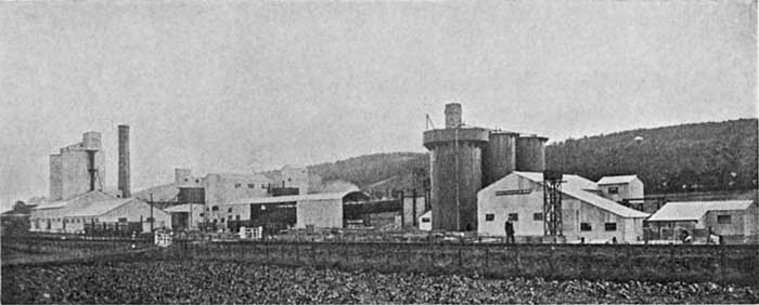 Fig. 1 - General View
The new works, a general view of which is shown in Fig. 1, replace a smaller plant started by Mr. Benton in 1921, consisting of a battery of improved-type chamber kilns (Note 4), and which included Edgar Allen machinery for the preparation of the raw materials and for the grinding of the cement clinker. The new cement works has been erected alongside, incorporating many up-to-date features, and including a rotary kiln for the production of 40,000 tons of cement clinker per annum. Provision is made for the erection of a second rotary kiln alongside the first kiln, and all the auxiliaries such as elevators, conveyors, etc., are large enough to handle the increased product when the second unit is installed.
The raw materials available include the upper and middle chalk and marl (Note 5), varying in content of calcium carbonate from 98 to 42 per cent., and there are ample quantities of these raw materials for over 100 years' production. At present only the middle chalk and marl are being used, these materials being adjacent to the works and therefore the most accessible.
Overburden to be removed from the top of the chalk is very slight, at some parts being only about 6 in. thick, and after loading into one-cubic-yard skips it is power hauled and tipped in an old working. A Ruston caterpillar-crane type steam navvy is used for digging the chalk, which is of a soft nature and easy to handle. The digger-bucket delivers direct into side-tipping wagons of 1 cu. yd. capacity running on a 2-ft. gauge railway with rope haulage. A double track is provided with an endless steel rope having an approximate range of 1,000 ft. The haulage gear is driven by an electric motor; one track is used for hauling full wagons to the washmill and the other for returning empties. The digger works alongside the incoming wagons and parallel with the track, there being a movable filling-hopper which advances or retires with the digger and arranged so that the bucket discharges direct into the stationary wagon under the hopper without the necessity of operating levers and doors; this is a great convenience in wet weather when the material is sticky. The wagons are each fitted with automatic catches for engaging or disengaging with the rope, so that the amount of labour required for operating the haulage gear is reduced to a minimum. This saving of labour shows itself throughout the works; the only labour required for skilled maintenance to keep the whole of the mechanical and electrical plant in efficient working order amounts to two engineers and a blacksmith.
The chalk wagons are tipped by hand into a 20-ft. diameter washmill. A hand-quarrying gang is employed to provide the small amount of marl or high-calcium material required to correct the chemical composition of the wash (Note 6).
The slurry leaving the washmill contains approximately 40 per cent. of water. The washmill is large enough to provide slurry for two kilns, so that no addition will be required to this department when the second kiln is put down. The slurry gravitates from the washmill to a vertical steel-cased bucket-elevator, which discharges at sufficient height to feed a battery of three Allen slurry separators. These separators take out of the slurry any coarse particles that have not been sufficiently reduced in the washmill, and these return by gravity for further washing.
The finished slurry from the separators flows through a series of wooden launders to the suction pit of the slurry pumps, the fineness being such that less than 5 per cent. is retained on the 180-mesh sieve. The finished slurry is pumped to storage tanks by a set of three-throw plunger pumps 8⅝ in. diameter by 16 in. stroke. Three storage tanks are provided in mild steel, 24 ft. diameter by 48 ft. total height, the bottom cones being tapered to a 6-in. diameter outlet and connected together by pipes and valves so that the slurry contained in any tank can be used for the kiln feed as desired (Note 7). The tanks are at ground level, with an access ladder to the top for operating the air supply used for agitating the slurry in the tanks.
For this purpose a two-cylinder air-compressor manufactured by Messrs. Broom & Wade, Ltd., of High Wycombe, supplies the necessary air pressure. Inside their periphery the tanks have a series of 1-in. diameter pipes with special nozzles leading down to the cone portion, and when it is required to agitate the slurry to prevent the solids settling out the compressed air is turned on; the escaping air passing up through the mass causes ample agitation to keep the slurry in liquid form so that it will run by gravity to a further set of pumps providing the feed to the kiln. Each tank holds about 650 tons of slurry, and as one at least is always kept full there is sufficient storage to keep the kiln running over week-ends and at such times when unforeseen stoppages might be enforced.
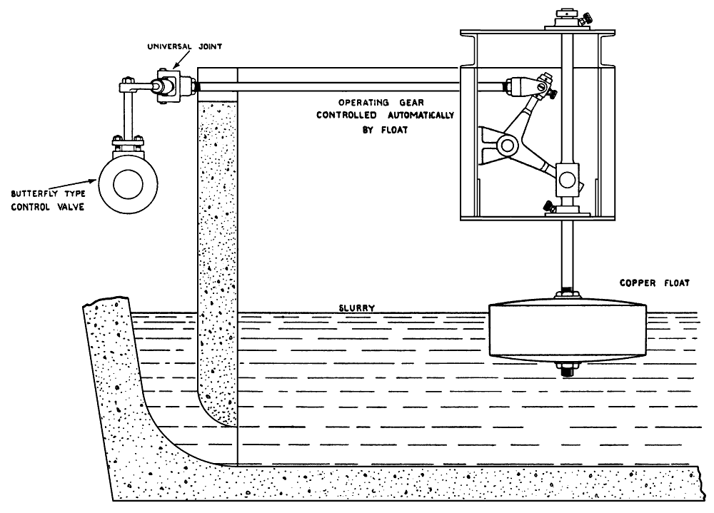 Fig. 3 - Butterfly Float Controlled Valve for Slurry Mixer
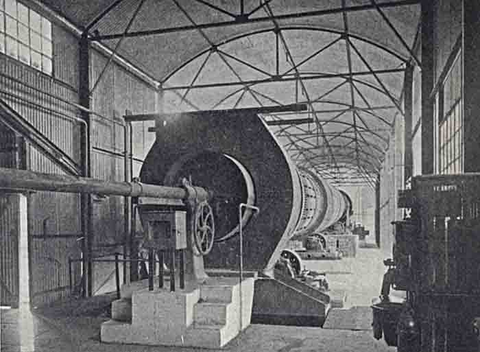 Fig. 4 - Rotary Kiln
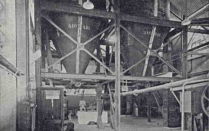 Fig. 5 - Coal Mill House
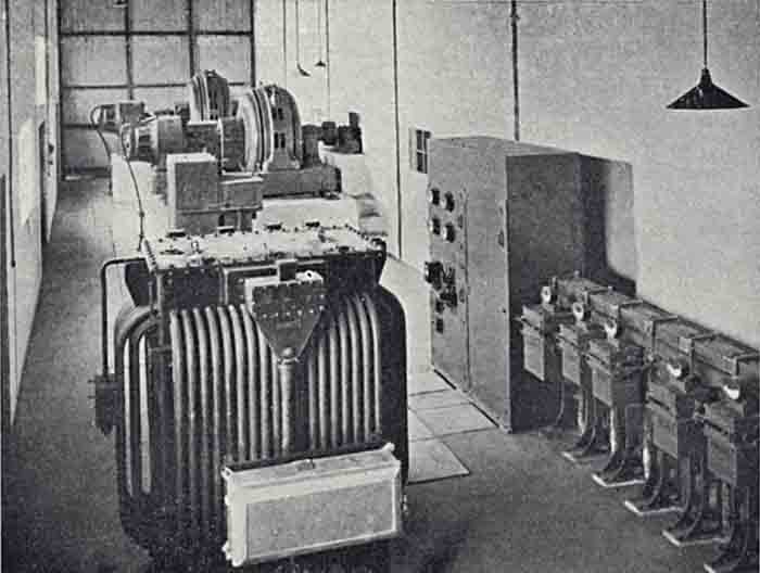 Fig. 6 - Motor, Transformer and Switchgear Room
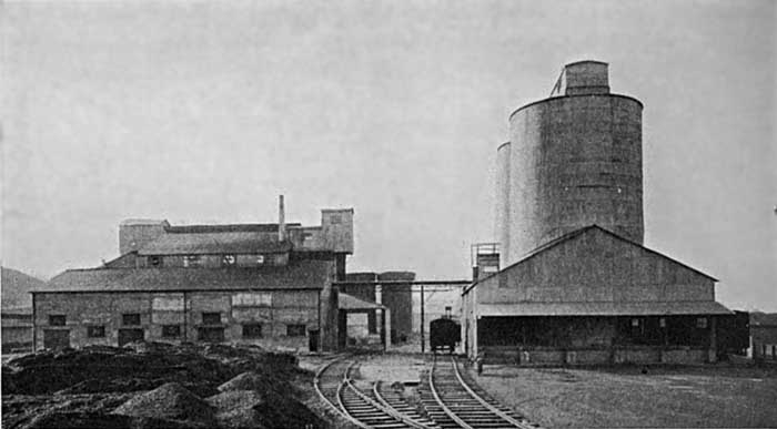 Fig. 2
A special feature in connection with the suction pit of the kiln-feed pumps is an arrangement of automatic float valve which controls the flow of the slurry from the storage tanks and prevents flooding of the open pit due to the head of slurry in the storage tanks. The float valve is of Alley & Maclellan's make, and will shut off the supply of slurry automatically whenever the pumps feeding the kiln are stopped.
The water supply to the works is obtained from three wells situated near the compressor house. The wells are 180 ft. deep, and have air-lift pumps which lift the water to a large storage tank which supplies the whole of the works, including the washmill and water-cooling system on the kiln bearings.
The rotary kiln is of combined kiln and cooler type (Note 8), carried on five cast-steel tyres of substantial dimensions with supporting rollers and beds. Driving gear is of cast steel, and is fitted with a countershaft and driving pulley for belt drive from a variable-speed motor. The kiln is 7 ft. 6 in. internal diameter by 185 ft. total length, and has an enlarged burning zone 9 ft. diameter. The kiln is lined with firebrick, and has slurry lifters at the inlet end. The last 20 ft. at the outlet end is fitted with lifters which cause the hot clinker to fall through the cool air, required for combustion, which is passing up the kiln, preheating the air and cooling the clinker at the same time. Another advantage of this type of combined kiln and cooler is that the foundations are much less in height and the kiln is more accessible than in the case where the cooler is separate and placed underneath the kiln.
The slurry is fed automatically to the kiln-feed pipe by a rotating feeder driven from the kiln, so that the speed varies in the same ratio as the revolutions of the kiln. A constant head of slurry in the feed tank also ensures an even flow. The kiln gases are withdrawn by an induced-draught fan delivering into a brick chimney, and the kiln dust-chamber is provided with a chain-scraper conveyor which continuously removes the dust deposited by the gases on their passage from the kiln to the fan. The conveyor delivers the dust into the suction pit of the kiln slurry pumps, and automatically returns to the kiln for burning.
The kiln is fired by powdered coal. (Fig. 4 is a photograph from the firing end.) Temperature of flue gases and draught measurement are diagrammatically registered on the burners' platform, and all controls are readily accessible to the burners' hand. The coal is dried before grinding in an Allen double-shell dryer, the final moisture not exceeding 1 per cent. From the dryer the coal is fed to a "Stag" combination tube mill 5 ft. diameter by 28 ft. long, driven by a 200-h.p. slow-running motor direct coupled to the mill countershaft and driving through one set of machine-cut spur gears. The powdered coal as it is delivered from the mills is elevated to two mild steel storage bins, one of which is used for feeding to the coal firing pipe, while the other provides storage for week-ends, etc. The primary air is provided by a high-pressure fan, and the air pressure conveys the fuel through a long telescopic pipe protruding well into the kiln and past the cooler portion. Both coal bins are provided with extracting screws with variable-speed drives capable of adjustment by the kiln burner. Fig. 5 is a view of the coal mill house with coal-firing equipment for the kiln.
The clinker as it issues from the kiln is conveyed and elevated to large clinker silos above the cement grinding mill. Gypsum is also handled in a similar manner, for which a separate silo compartment is arranged. Both clinker and gypsum silo outlets are fitted with automatic table feeders which discharge into the feed-drum of the clinker grinding mill. This mill is a "Stag" combination tube mill 6 ft. diameter by 32 ft. 6 in. long, driven in a similar manner to the coal mill by a slow-running motor of 350 h. p. direct-coupled to the mill shaft. A special feature in the design of the plant is that both the grinding-mill motors are arranged in a room partitioned off from the mills so that they are free from dust. Fig. 6 is a view of this motor room, which also houses the transformers and electrical switchgear.
From the cement mill the finished cement is conveyed to two large concrete silos, illustrated in Fig. 2, with railway loading docks on both sides and one end reserved for loading the sacks into road vehicles, of which five can be loaded at one time. Incidentally it is interesting to note that all the works sidings are laid on a gradient so that no shunting in the yard is necessary, and as the Great Western Railway is alongside the works this forms a very cheap and convenient method of dealing with the railway traffic. The Company produces a rapid-hardening cement known as "Chinnorcrete", and the following particulars are taken from test certificates issued by Mr. R. H. Harry Stanger, dated December 17th, 1928, and March 1st, 1929:
| Fineness residue % | |
| 76×76 sieve | 0.2 |
| 180×180 sieve | 1.6 |
| Setting Time minutes | |
| Initial | 75 |
| Final | 130 |
| Gauged with 22% water | |
| Soundness: Le Chatelier | |
| mm after 24 hours | 1.0 |
| Tensile Strength pounds per square inch | |
| Neat Cement | |
| 7 days | 930 |
| Gauged with 22% water | |
| Sand : Cement 3:1 (Note 9) | |
| 1 day | 482 |
| 2 days | 582 |
| 3 days | 637 |
| 4 days | 655 |
| 5 days | 670 |
| 6 days | 692 |
| 7 days | 713 |
| 28 days | 757 |
| 3 months | 792 |
| Gauged with 8% water | |
The cement plant is driven electrically throughout, the current being supplied from the Borough of Aylesbury Electricity Works, eleven miles distant, through duplicate overhead lines (Note 10). Power is received at 10,250 volts, and the Works are fed through a Ferranti transformer, 865 K.V.A., giving a 400-volt, 3-phase, 4-wire supply for power and lighting, provision being made for an additional transformer to be supplied at an early date. An auxiliary low-tension supply will shortly be provided, and arrangements will be made so that when the main plant is shut down the lighting and workshop motors can be run from the auxiliary supply. The power transformer feeds a Switchgear and Cowans cubicle-type switchboard from which it is distributed by the same make of industrial draw-out type switchgear to the motors and lighting of the works.
The complete electrical installation of the works has been carried out by the Lancashire Dynamo & Motor Co., using their "Maxtorq" induction motors and "Lancashire" self-starting and self-synchronising motors for the specially heavy low-speed drives. The 350-B.H.P. 187.5-R.P.M. self-starting synchronous motor driving the cement tube mill, and the 200-B.H.P. self-starting synchronous motor driving the coal tube-mill, are each designed to start up against twice full-load torque four times per hour, and are operated by Brookhirst starting panels having a single ratchet handle, a regulator handle arranged for locking in one position, and "stop" push buttons. The entire operation of starting up one of these motors, including self-synchronisation, is therefore carried out by operating one simple ratchet handle. Each of these motors drives through a flexible coupling and straight-tooth gearing on the mill. They are capable of running at a leading power factor of 0.85, which allows of the power factor of the whole installation being brought up to unity at full load.
The synchronous motors are started up like ordinary slip-ring induction motors by means of starters in the rotor circuits. When the motor approaches synchronous speed the exciters coupled to the motors build up their voltage, and the motors pull into synchronism and continue to run as synchronous motors. They have large overload capacity as synchronous machines, and under normal running conditions will not fall out of step even with a considerable amount of overload; should any abnormal load be imposed sufficient to force the motors out of step they continue to run as induction motors until the load falls and then the motors pull into step and again run as synchronous machines.
A 125-B.H.P. 485-R.P.M. "Maxtorq" motor drives the washmill, separators, and slurry elevator, and is designed to start up against twice full-load torque; it is controlled by a Brookhirst auto-transformer type starter. All the motors for driving elevators, pumps, fans, etc., are of the "Maxtorq" single-speed type controlled by star-delta starters.
The majority of the leads are paper-insulated lead-covered and armoured cable, and precautions have been taken to prevent the cable being exposed to any excessive temperatures in the vicinity of the rotary kiln and hot-clinker elevators, etc. Triple earths are provided and arranged so that tests of their efficiency can be carried out. Foolproof interlocks and indicators have been provided where necessary.