The Ketton Portland Cement Company Limited was formed in 1928. The ancient disused Ketton freestone quarry (and 1100 acres of the parish) was acquired by Frank T. Walker of Sheffield in 1921, and he commenced re-opening the quarry for freestone and for aggregate for concrete products, as Walker's Ketton Stone Ltd. He engaged Parry & Elmquist to examine the prospects of a cement plant. During 1926-1927, financial backers for a potential cement company were sought, and in 1927, Thomas W. Wards agreed to take a controlling interest, providing capital through a new share issue.
Parry & Elmquist, as agents for FLS, ordered most of the mechanical plant from FLS, and implemented a standard FLS design. The onward technical management of the company was supervised by FLS and Tunnel. The initial 60,000 tpa plant began a long process of development of what ultimately became one of Britain's largest plants. The history of the plant closely parallels that of Hope - also an FLS project - which started up a few months later, and many interesting comparisons can be made. The kilns described here are at the smaller end of the size range, and Ketton progressively uprated with more-or-less identical kilns, the fourth being added in 1954. A good quality video clip of the four-kiln plant in action can be seen at East Anglian Film Archive.
The following is the text of an article in The Engineer (CXLVIII, December 13, 1929, pp 640-643), shortly after the commissioning of the plant. A similar article, using much the same material, appeared in Cement and Cement Manufacture (III, July 1930, pp 954-960). A further article followed four years later in Engineering (CXXXVI, October 27, 1933, p 463). All three articles are believed to be out of copyright.
Values of imperial units (as of 1929) used in the text (alphabetical order): 1 acre = 0.40468424 Ha: 1 ft = 0.30479947 m: 1 gallon = 4.5460756 dm3: 1 HP (horse-power) = 0.7456998 kW: 1 inch = 25.399956 mm: 1 psi (pound-force per square inch) = 6.89478 kPa: 1 ton = 1.01604684 tonne: 1 yard = 0.91439841 m.
The Ketton Portland Cement Works
The newly erected Cement Works of the Ketton Portland Cement Company, Ltd., are situated just outside the picturesque little village of Ketton, in Rutland. One of the reasons for that part of the country being chosen was that there is there a famous freestone quarry which records are said to prove was being worked as long ago as, at any rate, 800 years (Note 1). It was from it, we are informed, that stone used in the construction of York Minster, and St. Dunstan's Church and the Law Courts in London was obtained. The overburden above the freestone consists of clays of varying composition and oolitic limestone, both of them materials suitable for the manufacture of Portland cement. Until recently, the quarry had not been continuously worked for some considerable time, but in the course of the long period during which it was being actively operated many hundreds of thousands—it is said as much as 3,000,000—of tons of the overburden had been removed, in order to get at the freestone, and dumped on to heaps (Note 2). It is those heaps which are now being drawn upon to provide raw material for the cement works, and they are readily and cheaply exploited, since the material has been already quarried, and no blasting is required. Even when they are exhausted, however, the company owns many hundreds of acres of land which is reported to be of the same formation, so that, so far as raw materials are concerned, the works may be said to be more than amply provided. Incidentally, it may be remarked that, in the course of operations now in progress, a certain amount of freestone of excellent quality is still being uncovered and is finding a ready sale.
Another essential—water—is obtainable from springs and the natural drainage from the company's land, and, if necessary, from the river Chater and the river Welland, which both flow through the company's estate.
As regards fuel, coal can be brought on to the site by means of a direct connection with what was formerly the Midland main line connecting Peterborough and Leicester, which now forms part of the L.M.S. Company's system, and the same connection provides the means by which cement may be dispatched by rail. The finished product may also be sent away readily by road, since the works adjoin the main road between Stamford and Leicester (Note 3). On all counts, therefore, the works may be regarded as admirably situated.
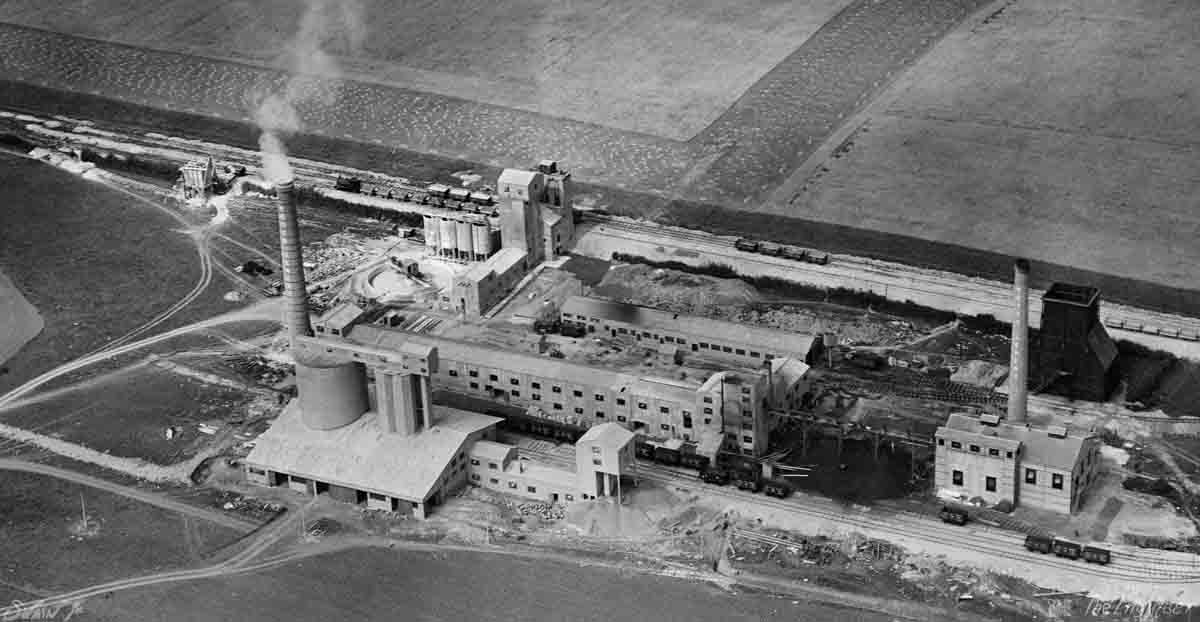
Figure 1. Aerial view of works
As at present built, the establishment, an aerial view of which, taken just after it was completed but before the approach road to it was constructed, is given in Fig. 1, is intended to produce 60,000 tons of Portland cement per year, but the arrangements are such that that output could be trebled by the addition of further machinery (Note 4). The general lay-out of the factory is shown in Fig. 2, and, as we shall show, care has been taken to make the progress of the raw material through the various processes until the final product is sent away as direct as possible. The quarry lies some three-quarters of a mile from the factory, and the limestone and clay, which are excavated by a steam navvy—see Fig. 3—are brought from it to the site in 4 cubic yard wagons and 12-ton trucks respectively by locomotives on a standard gauge railway. The line is, for the most part, on a falling gradient, since the floor of the quarry is at a considerably higher level than is the factory, so that only the comparatively light weight of empty wagons has to be pushed uphill.
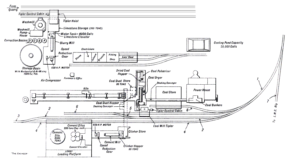
Figure 2. General Plan of the Ketton Portland Cement Works
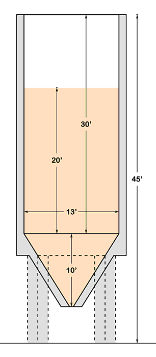
The point of entry of the raw materials on to the site is shown in the left top corner of Fig. 2. The clay wagons are taken along the rails nearest the factory, and the clay is discharged directly from the wagons into a wash mill, which is of the ordinary revolving harrow type, and calls for no particular mention (Note 5). In it the clay is washed into slurry, which escapes through fine gratings arranged in the sides of the mill in the usual manner. The slurry is lifted by force pumps capable of dealing with 20 tons per hour (Note 6), and driven by a 20 H.P. motor, and is discharged into either one or the other of the correction basins A or B, which may be seen close to the wash-mill (Note 7). These basins, a view of the tops of which is given in Fig. 4, are circular reinforced concrete tanks, 13ft. in diameter and 80ft. high, which are capable of containing 115 cubic yards of slurry (Note 8). Each is furnished with a system of air pipes and nozzles by means of which compressed air at a pressure of 70 lb. per square inch, which is supplied from an electrically-driven air compressor in an adjoining building, can be forced into the slurry to agitate it. The motor driving this compressor is of 50 H.P. Either one or other of the basins A and B is always kept full of clay slurry, and average samples are taken at frequent intervals by the Works Chemist for analysis in order to ascertain whether the slurry contains the desired proportions of silica, alumina, and iron oxide. If it does not, the requisite correction is made by the addition of more of the constituent in which there is a deficiency. As the company has on its property deposits of both high-silica and high-alumina clays, containing iron oxide, there is no difficulty in obtaining slurry of exactly the composition required. It is believed by the company that at no other cement works is the same amount of trouble taken to correct the clay slurry (Note 9), and it attributes the high quality of the cement it produces to the care taken at Ketton in this direction.
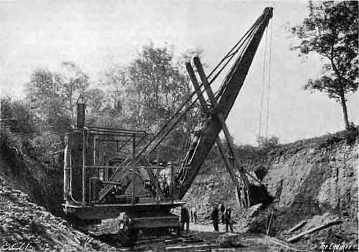 Fig. 3: Steam Navvy in Quarry |
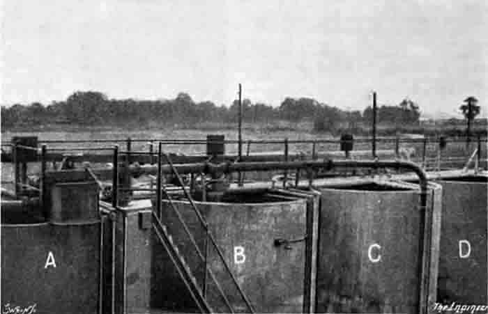 Fig. 4: Tops of Correction Basins |
The trucks containing the limestone are brought in along the centre line of rails, and each in turn is stopped in front of a tippler hoist building which is alongside the washmill. There it is placed on a cradle, which can be lifted by electrically-operated mechanism—see Fig. 5—to a height of some 28 ft. above rail level, where its contents are automatically tipped into a hopper. From the hopper the stone, which arrives in sizes varying from quite small pieces up to lumps a ton or so in weight, is led by a feeding arrangement. which has a capacity of some 50 tons per hour, to a crusher in which it is broken up into pieces not greater than ½ in. in diameter. The crushed limestone goes from the crusher into an elevator which discharges it into a silo of approximately 200 tons capacity. The advantage of having the storage silo is that, as the grinding mill is continuously in operation, it can be kept going for a number of hours with the stored material, when the quarrymen are not at work or should there be any breakdown at the quarry or in the tippler hoist, &c.
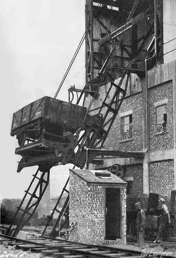
Figure 5. Truck Hoist and Tippler. All FLS plants moving raw materials by rail (and most did) had variants of this.
The crushed stone is fed to the grinding mill, which is a combination of a ball mill and a tube mill, at the rate of 14 tons per hour, and as it enters it, clay slurry, in the desired proportion, is added from either of the correction basins A or B, together with water. As a matter of fact, the quantity of clay allowed to enter is just slightly less than that actually required for the correct mixture. The reason for this is explained later on. The mill is of the ball type and is divided into four compartments, the first compartment containing steel balls from 3½ in. to 2½ in. in diameter; the second, balls from 2½ in. to 2 in. in diameter; the third, balls from 2 in. to 1½ in. in diameter; while the fourth is charged with what are known as "Cylpebs", which are short pieces of round hardened steel about ⅝ in. in diameter and 1 in. long. The total weight of these grinding bodies in the mill is 44 tons. The mill casing, which is of the usual pattern, measures 39 ft. 5 in. in length by 7 ft. 3 in. in diameter. It is revolved at a speed of 20 revolutions per minute by an electric motor of 650 H.P. which was supplied by Metropolitan-Vickers. The speed of the motor is 720 r.p.m., and, through a reduction gear, that speed is reduced to 20 r.p.m. at the shaft driving the mill (Note 10). The combined mixture of limestone and clay slurry leaves the mill ground to a very fine slurry, the solid matters in which are claimed to be in an even finer state of subdivision than are those in finished cement. The slurry discharged from the grinding mill is pumped to either of the two basins C or D—Fig. 2 which are similar in size and construction to the basins A and B, and which, like them, are both furnished with a system of pipes and nozzles by means of which compressed air can be forced up through the slurry (Note 11). Here, again, the works chemist is continuously taking samples and analysing them.
As has been said, rather less clay than the absolutely correct quantity is sent into the grinding mill along with the limestone. The purpose of that arrangement is that the chemist, when he has found by analysis exactly how much the mixture is lacking in clay, may give directions for the requisite quantity of that material to be added to make the final mixture absolutely correct. For the purpose of making the addition a trough is led over the tops of all four basins A, B, C and D, and the requisite quantity may be lifted into the trough from A or B and delivered into C or D, as the case may be; gaps, which can be opened or closed at will by means of metal plates, being left in the trough for the purpose. The deficit in clay content is quite small, but it is sufficient to enable the chemist to keep that absolute control over the mixture which is so essential in the manufacture of Portland cement for the production of an unvarying final product.
When the desired mixture is obtained, the slurry is allowed to flow by gravity into a large circular reinforced concrete storage basin, which is 66 ft. in diameter and 12 ft. deep, and which is capable of containing 1500 cubic yards of slurry (Note 12). A system of sun-and-planet motion stirrers keeps the slurry continuously agitated, and the tank is further furnished with an arrangement of pipes and nozzles by means of which compressed air is forced up through the slurry, and increases the agitation. It is claimed that this combination of methods—mechanical and pneumatic—ensures a better mixture of the slurry than is obtained in any other manner, and still further tends to the turning out of a regular final product.
From this storage tank the slurry is pumped up as required to the feeding end of the kiln by means of an electrically-driven centrifugal pump. The amount pumped is always in excess of the amount actually required fully to feed the kiln. The discharge from the pump is into a small tank which is fitted with an adjustable overflow. Revolving in this tank is a shaft furnished with buckets which dip down beneath the surface of the slurry. These buckets, as they revolve, lift definite quantities of the slurry, since the level of the slurry is kept constant by the adjustable overflow, and deliver it into a chute which terminates in a pipe that, in its turn, delivers the slurry into the kiln. The bucket shaft is driven by a small electric motor, the speed of which, and hence the quantity lifted by the buckets in a given time, is controlled from the firing platform. The overflow from the measuring tank is allowed to flow back to the storage basin.
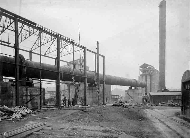
At the moment, there is only a single kiln for converting the slurry into cement clinker. It possesses several features of interest. It is 272 ft. long in all (Note 13). For a length of 162 ft., the upper portion has a diameter of 7 ft. 4 in., the whole of the remainder being 9ft. 4 in. in diameter. It is carried in the usual manner on steel rings revolving on rollers which dip into water, and is revolved in the ordinary way by means of a toothed wheel arranged midway in its length, which is driven by motor through reduction gearing. The motor is of 55 horse-power. The speed of the kiln in ordinary working is about one revolution per minute.
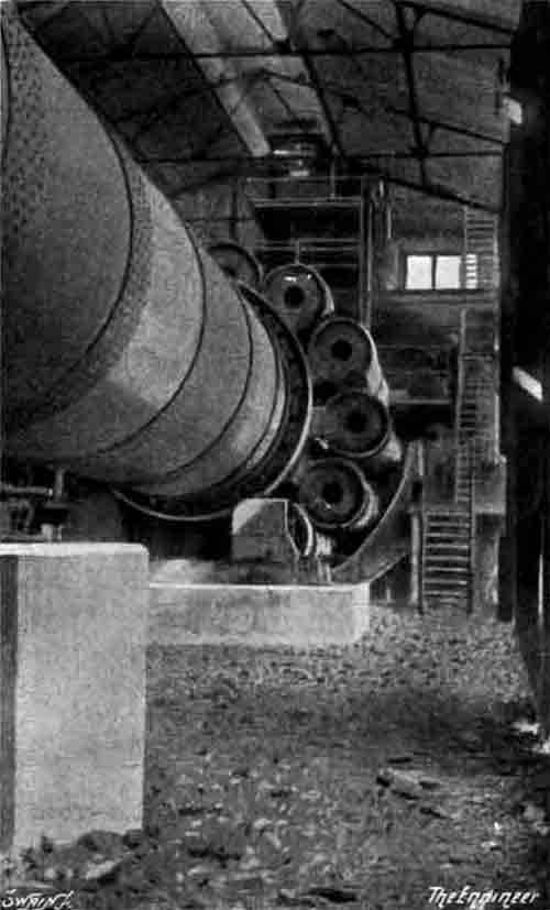
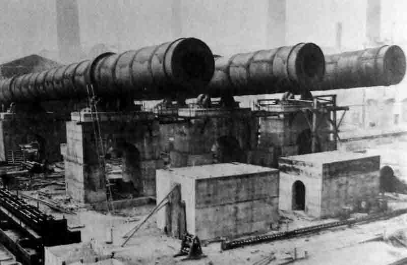
Our readers will remember that, in the majority of the cement works in operation in this country, the burned clinker is cooled in a separate rotating cylinder arranged either in line with the kiln or taken back immediately underneath it. With the kiln at Ketton the cooling is effected in a series of twelve circular steel cylinders 14 ft. 6 in. long and 3 ft. in diameter, which are attached at regular intervals round the periphery of the shell of the kiln at the discharge or firing end, their axes being parallel with the axis of the kiln (Note 14). Two views of the kiln showing these cooling cylinders are given in Figs. 6 and 7. Formed in the periphery of the kiln are also twelve openings, each of which communicates with one of the cooling cylinders, and through these openings the hot clinkers find their way into the latter. The cylinders, which are, of course, inclined at the same angle as the kiln and revolve with it, are furnished internally round their peripheries with series of chains which cause the clinker to be tossed about as it passes down the cooler to the discharge end. A portion of the air necessary for the combustion of the fuel used for firing the kiln is allowed to pass up through the coolers on the way to the latter, and the clinker, by the action of the chains, is made to fall in cascades through it. The result is twofold: the air is heated and does not enter the kiln cold, and the clinker is cooled. The arrangements and dimensions of the coolers are such, in fact, that, whereas the clinker, when discharged, is so cool that it can be picked up without serious discomfort in the naked hand, the air as it enters the kiln is very nearly as hot as the clinker which has just left it (Note 15), so that the loss of heat is minimised.
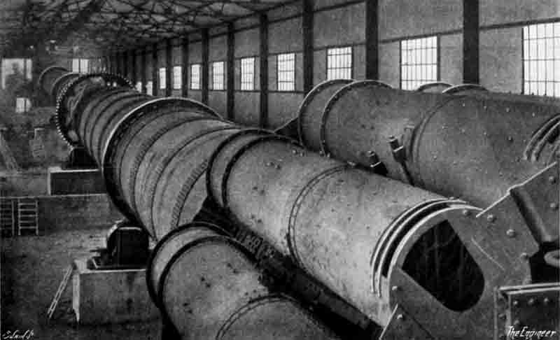 Above: Fig. 6: View of Kiln from Firing Platform showing Clinker Cooler Right: Fig. 7: View of Kiln and Coolers |
 |
One of the claims made for this method of cooling the clinker, in addition to the points already mentioned, is that with it, the kiln can be pitched much lower than when a separate cooler is employed, with a consequent saving in capital cost, both on account of the lower foundations required and because buildings of less height are necessary.
There is another feature of the kiln to which attention must be drawn. It is that for the upper 80 ft. or so of its interior there are fitted series of chains, something after the manner of the chains in the coolers (Note 16). In the kiln, however, these chains are so arranged as to give a corkscrew-like motion to the slurry as it is fed into the kiln, and to the material as it is dried in its passage downwards towards the clinkering zone. Various advantages are claimed for this innovation. One is that the material being dried and burned is prevented from being formed into large lumps, so that the burning is more regular, and another is that it, to a large extent, prevents the lighter portion of the dried slurry being carried away to the chimney. It is certainly a fact that, with the exception of an enlarged hopper-shaped chamber of sheet steel into which the upper end of the kiln is led, there is no special provision for catching dust, the gases coming from the chamber being led either direct to the base of the chimney or through the duct of an induced draught fan, and thence direct to the chimney, as may be desired. Yet we are assured that there is no excessive discharge of dust from the chimney, and that no complaints of the deposition of dust on the surrounding vegetation have been received (Note 17). We ourselves did not notice any such deposition, but it has to be stated that, prior to our visit, the works had only been in operation for some few weeks. The chimney, we may add, is 130 ft. high and 8 ft. in inside diameter (Note 18).
The kiln is fired by powdered coal, the pulverising being done on the site. The coal comes to the factory in railway wagons and is pushed along lines 1 and 2 by the cross-over road 5 to the siding 6—see Fig. 2. From there the trucks can travel by gravity, since siding 6 is laid with a downward gradient. As they arrive at the coal tippler—see Fig. 2 each truck in turn is made to discharge its contents into an under-ground hopper. From there the coal is raised by an elevator which has a capacity of 40 tons per hour, and may be delivered by mechanically-operated conveyors, either (a) into a silo arranged above a coal dryer to be referred to directly; or (b) into an adjacent coal store which is capable of accommodating 2000 tons; or, alternatively, (c) into bunkers over the boiler-room of a power-house, which will be described later. It may here be explained that coal can also be delivered direct to the store from wagons run on to siding 8. From the silo in the dryer building, the coal is fed into a dryer which is of the cylindrical revolving type with interior and exterior passages for the heated gases. On being discharged from the dryer the coal is lifted by an elevator and discharged into a hopper arranged above a grinding mill in an adjoining building. From the hopper the coal is fed by a feeding table into a ball mill, which is driven by a 125 HP motor, where it is ground to such a fineness that there is only a residue of some 5 per cent. on an 180 x 180 sieve. The ground coal is lifted and conveyed to a hopper immediately above the kiln firing platform, and, when that is full, the discharge is automatically diverted to a large store nearby, which is capable of containing 80 tons. This store, which is built of reinforced concrete, holds enough fuel to keep the kiln in operation for at least twenty-four hours without running the grinder. For drawing on this supply there are two worm extractors, the delivery from which is into the conveyor that lifts the coal dust coming from the grinder. The fuel can therefore be transferred, as desired, from the store to the hopper above the kiln.
The coal for firing the kiln is withdrawn from the overhead hopper by means of a worm conveyor, the discharge from which is into the pipe which is taken into the firing end of the kiln. The fuel is propelled into the kiln by an electrically-driven centrifugal fan which draws its air either from the atmosphere or from the clinker coolers round the kiln or from both sources. The rate of supply of fuel and the speed of the fan are, of course, controllable from the firing platform, on the wall at the side of which there is a pyrometer which shows the temperature in the smoke chamber.
We have already described the feeding of the slurry into the kiln, and the cooling of the clinker after burning. We may here say that any lumps which may be formed, and which are too large to pass through the holes in the kiln leading to the coolers, pass along to the ends of the latter, where they fall into a large hopper, whence they can be removed for disposal. It is the company's practice not to attempt to break up and grind these large lumps for fear lest any clinker that is not thoroughly burned might injure the quality of its cement (Note 19).
The clinker discharged from the coolers is taken by a shaking conveyor and lifted by an elevator to such a height that it can be delivered either to a clinker silo arranged above a grinding mill or deposited in a clinker store outside the mill building (Note 20). The grinding mill is of the four-compartment type, and is similar in design to the mill which grinds the slurry. It is driven at a speed of 20 r.p.m. by a 650 H.P. motor, which itself runs at 720 r.p.m., through reduction gearing. The clinker is fed to the mill by feeding table at the rate of some 12 tons per hour, the necessary quantity of gypsum—ordinarily from 2 to 3 per cent.—being added at the same time. The gypsum is stored near the mill building, and after being reduced in a crusher to the desired size, it is elevated to a hopper above the mill, whence it can be fed to the latter.
It is the company's practice to grind the cement to such a fineness that not more than 3 per cent. remains on a 180 x 180 mesh sieve. The finished cement as it comes from the mill is taken by a screw conveyor to the foot of an elevator, by which it is lifted to a height of some 75 ft., and is then taken by conveyors either to one or other of four hexagonal (Note 21) reinforced concrete silos, each capable of containing 250 tons, or to a large circular silo—also of reinforced concrete—which has a capacity of 3500 tons (Note 22). From whichever of these silos it is desired to draw, the cement is sucked by vacuum into automatic packers which are arranged on a platform, from one side of which the cement can be loaded direct into railway vans, while from the other side it can be dispatched by road in carts or lorries.
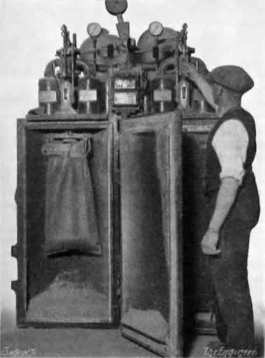
Figure 8. Automatic Vacuum Cement Packer
The automatic vacuum packers (Note 23) are formed with two compartments, each of which is furnished with an airtight door—see Fig. 8. While the sack in one compartment is being filled, the filled sack is being removed from the other compartment and an empty sack being inserted for filling. When a door is closed and the suction applied, the cement is drawn into a hopper, to a circular chute at the bottom of which the sack to be filled is clipped, and falls from that chute into the sack. When the desired weight has entered the sack—and the exact quantity required is automatically adjusted—the suction is automatically broken, the flow of cement is out off. and the door of the compartment opens. The sack is then detached from the chute and taken away on a hand barrow. While we watched the operation, the sacks, as filled, were being wheeled direct to a railway wagon, where the mouths were being closed by twisted wire. As a matter of fact, the "sacks" being used when we were there were of paper, and should perhaps be more properly termed "bags". We gather that the company makes considerable use of such paper bags, which can hold 1 cwt. of cement, for the dispatch of its product. Four thicknesses of fairly stout brownish paper are employed in making the bags, which are said to answer their purpose exceedingly well (Note 24). We may add that the vacuum filling machines are furnished with a window past which the cement can be seen travelling when the suction is on. It is therefore possible for the attendant to see if the machines are operating satisfactorily.
During the dispatch of a consignment of cement small samples are continuously being taken by the man operating the packer, all samples being placed in one receptacle. The works chemist can, therefore, obtain a test of an average sample of the cement sent away on any particular occasion. Samples of the cement are of course, frequently taken at various points, and for testing them and the slurry there is a laboratory which is equipped for all the necessary chemical and physical tests.
For convenience in getting loaded railway vans away from the cement building, the siding marked 4 on the plan is given a down gradient of 1 in 75 towards the siding 1, by which the empty vans come to the works from the railway. These empty vans are pushed by locomotives up line 2 to siding 3, and then run by gravity down siding 4 to the cement building, where the brakes are applied. When they are fully loaded the brakes are taken off and the vans run by gravity down the line 4 to the line 1. When the desired number of loaded vans has been collected on that line, they are coupled up and are taken in charge by a locomotive and first drawn on to and then pushed down the line 7 to the company's siding near the L.M.S. Railway, whence they are taken away by that company's engines. We gathered that at the present time a large proportion of the output of cement is going into the Sheffield district (Note 25).
It will have been understood from what has been said in the foregoing that the works are electrically operated throughout. In all, there are some thirty-five motors installed, and they vary in capacity from 650 H.P. down to ½ H.P. When the factory is in full operation, the demand for energy amounts on an average to 1300 kW. As it was found impossible to purchase electric power sufficiently cheaply from any outside source in the neighbourhood, the company decided to lay down a power station of its own (Note 26). The power plant comprises two Babcock and Wilcox water-tube boilers, each of which is capable of generating sufficient steam to operate the whole of the plant. Each boiler is furnished with its own economiser, and both are equipped with automatic stokers, which are fed in the ordinary manner from overhead bunkers. Steam at 210 lb. per square inch pressure is supplied to a turbo-alternator of 1850 kW capacity, made by the British Thomson-Houston Company, which runs at 3000 r.p.m., and generates three-phase current at 3300 volts. All the motors of 100 H.P. and over are worked at that pressure, but for the smaller machines the voltage is reduced to 440. For that purpose four single-phase transformers are arranged below the turbine-house floor, one of the four being kept in reserve. For lighting and heating purposes the 440 volts is further stepped down to 110 V in another transformer. The turbine exhausts into a surface condenser, and the circulating water is cooled by means of a cooling tower. An evaporator, which is operated by live boiler steam, is employed to provide the make-up water. There is room in the turbine-room for another larger generating unit.
Having regard to the distance of the factory from any engineering works which might be called upon to effect repairs, the company has rendered itself independent of outside aid by installing well-equipped blacksmiths', fitters', joiners', and electricians' shops, which contain all the machine tools, &c., that are likely to be required. There are also stores in which stocks of spare parts, steel, &c., are accommodated. The positions of these departments may be seen in Fig. 2. Adjoining them is a shed for four locomotives, which are required to keep the works going. Just outside the shed is a water tank with a capacity of 2200 gallons. This tank is fed from a main water tank which is arranged above the Raw Mill, and has a capacity of about 10,000 gallons.
Mention has already been made of the testing laboratory, which, we understand, is kept in operation continuously, night and day. Samples of cement and slurry are taken hourly and analysed. In addition, thirty-six tensile briquettes are made every day and some of them are tested at one, two, three, seven, and twenty-eight days. A number of 3 in. cubes with 1 cement to 3 of standard sand is also made and crushed at certain intervals.
The following figures of tensile tests of briquettes of 3 parts standard sand to 1 part "Ketco" Portland Cement—as the company's product has been named—have been given to us:—
| psi | MPa (Note 27) | |
|---|---|---|
| 1 day | 400 | 10 |
| 2 days | 525 | 17 |
| 3 days | 543 | 18 |
| 7 days | 635 | 29 |
—the British Standard requirement being 325 lb. per square inch. Neat "Ketco" cement, we are told, shows a tensile strength of 814 lb. per square inch at seven days as compared with the British Standard requirement of 600 lb. The initial and final setting times are said to be 2 h. 10 min. and 3 h. 6 min. respectively.
The company also produces a quick hardening cement, which is marketed under the name of "Kettocrete". Independent tests carried out by Messrs. Stanger, of Westminster, gave the following tensile strengths for briquettes made of 1 part of "Kettocrete" and 3 parts sand:—
| psi | MPa (Note 27) | |
|---|---|---|
| 1 day | 525 | 15 |
| 2 days | 612 | 21 |
| 3 days | 675 | 24 |
| 7 days | 712 | 34 |
| 28 days | 735 | 43 |
| Neat cement 7 days | 1212 |
Compressive strengths of 3 in. cubes made of 3 parts of standard sand and 1 part of "Kettocrete" gave the following results:—
| psi | MPa (Note 28) | |
|---|---|---|
| 1 day | 5400 | 37 |
| 2 days | 7185 | 50 |
| 3 days | 7785 | 54 |
| 7 days | 9193 | 63 |
| 28 days | 9696 | 67 |
The works were erected to the design of Parry and Elmquist, Ltd., Consulting Engineers, of Kirton Lindsey (Note 29), who also supervised the erection of the complete plant and the starting of the works. Most of the cement-making machinery was supplied by F. L. Smidth and Co., Ld., Victoria Station House, Victoria-street, London. The motors were made by the Brush Electrical Engineering Company, Ltd., and the Metropolitan-Vickers Electrical Company, Ltd., while most of the electrical starting gear was supplied by George Ellison, and the Mitchell Conveyor and Transporter Co., Ltd., provided the tippler hoist and coal tippler. We understand that Thos. W. Ward, Ltd., of Sheffield, are the sole distributors for Ketton cements.


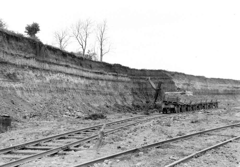 Picture: ©NERC: British Geological Survey Cat. No. P208264. The multi-coloured clay face. Clay loaded into side-tipper wagons.
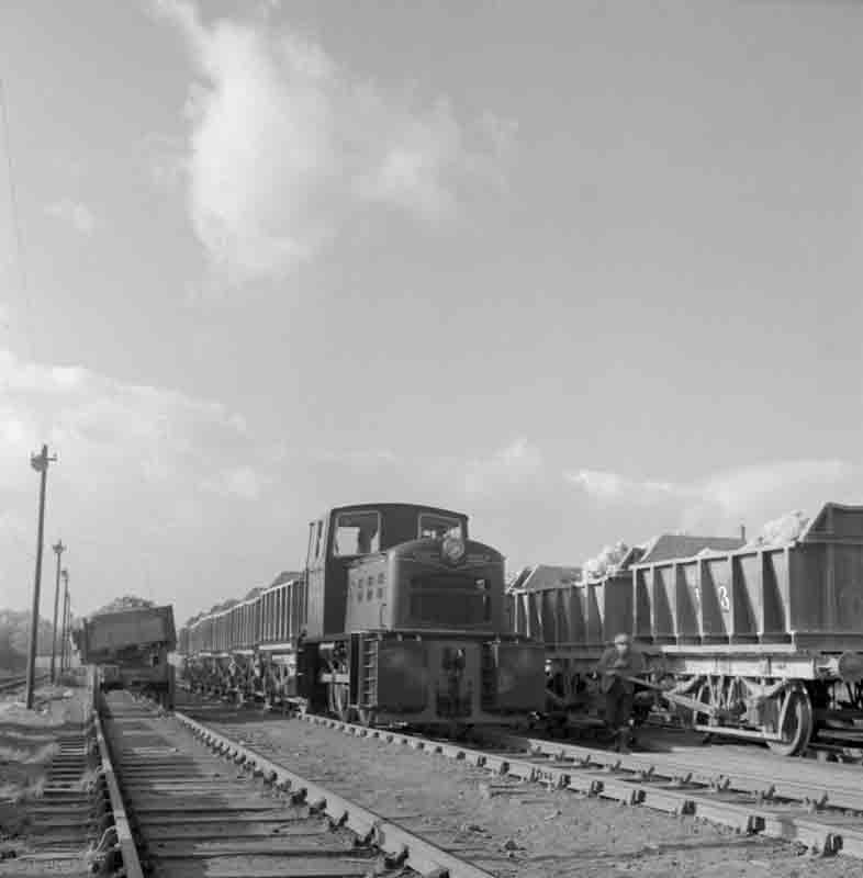 Picture: ©NERC: British Geological Survey Cat. No. P540546. Ketton raw material trains looking west. The clay washmills were on the south side and the limestone crusher on the north. All the rail was standard gauge.
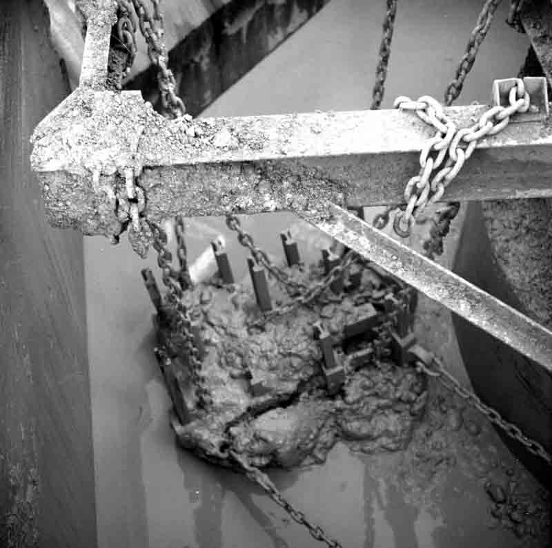 Picture: ©NERC: British Geological Survey Cat. No. P540581. In a clay washmill.
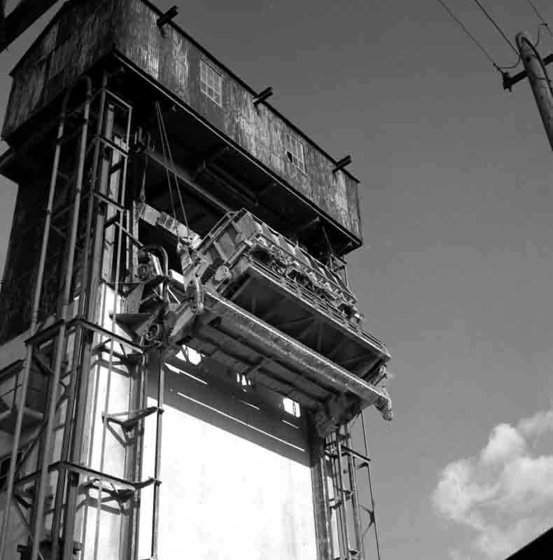 Picture: ©NERC: British Geological Survey Cat. No. P540580. The limestone tippler raising a stone truck with 15 tons of limestone to the top of the crusher feed hopper.
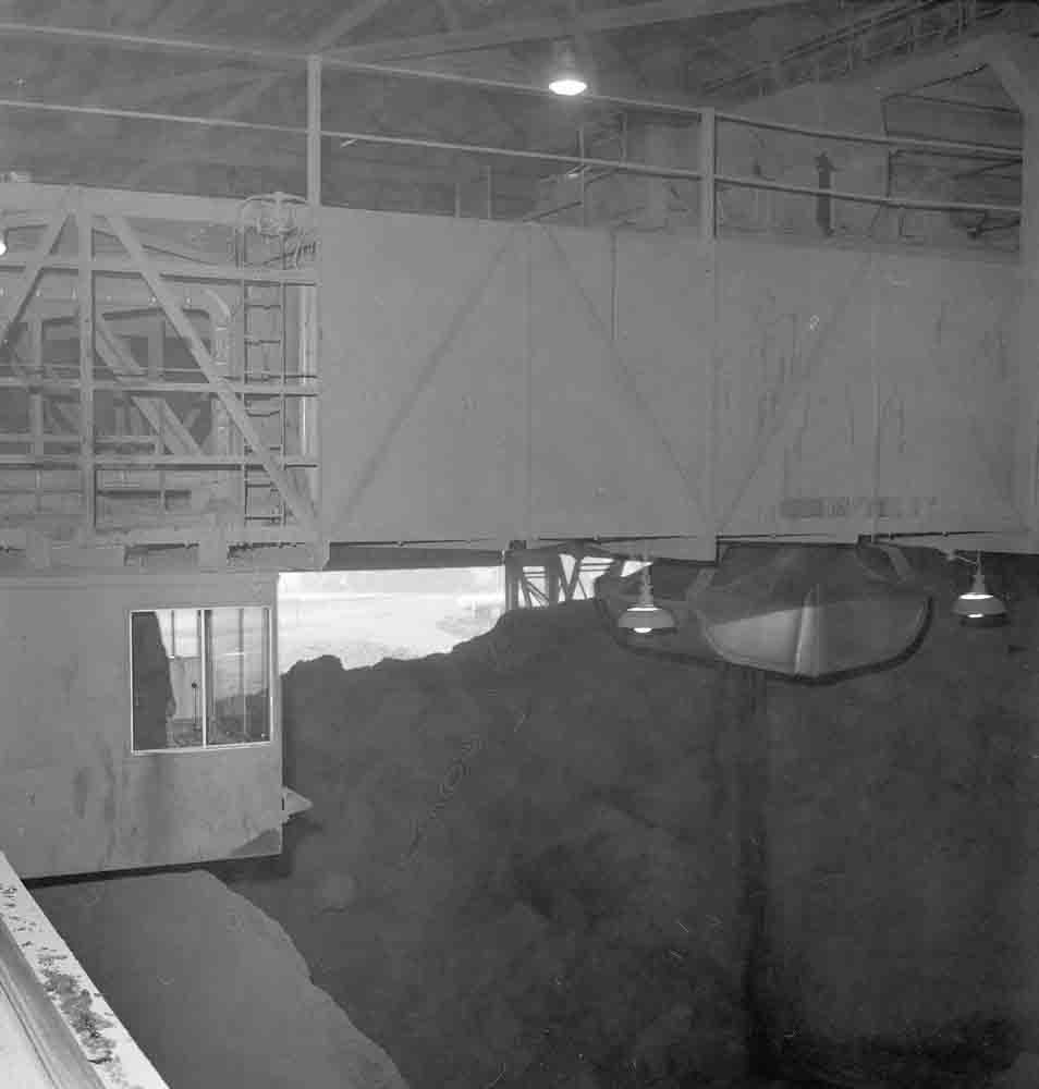 Picture: ©NERC: British Geological Survey Cat. No. P540323. A crane over the limestone pile at the west end of the store.
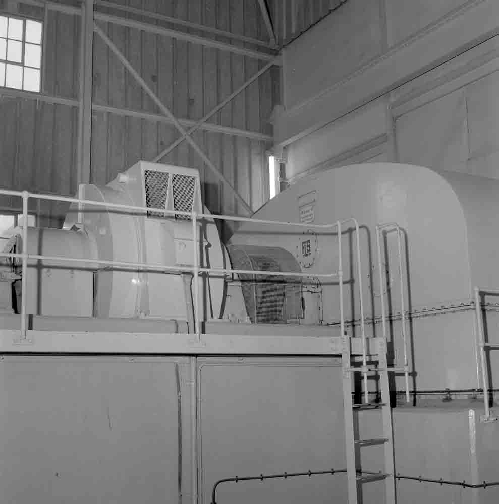 Picture: ©NERC: British Geological Survey Cat. No. P540328. Rawmill motor room with 1500 HP motor and Symetro gearbox.
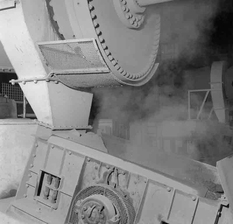 Picture: ©NERC: British Geological Survey Cat. No. P540547. Warm slurry leaves the rawmill over a Niagara screen.
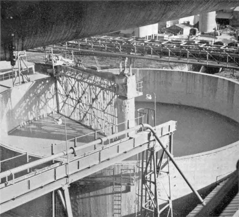 Picture: ©NERC: British Geological Survey Cat. No. P540545. The new kiln feed basin viewed from the precipitator. The kiln feed line and return flume are in the foreground.
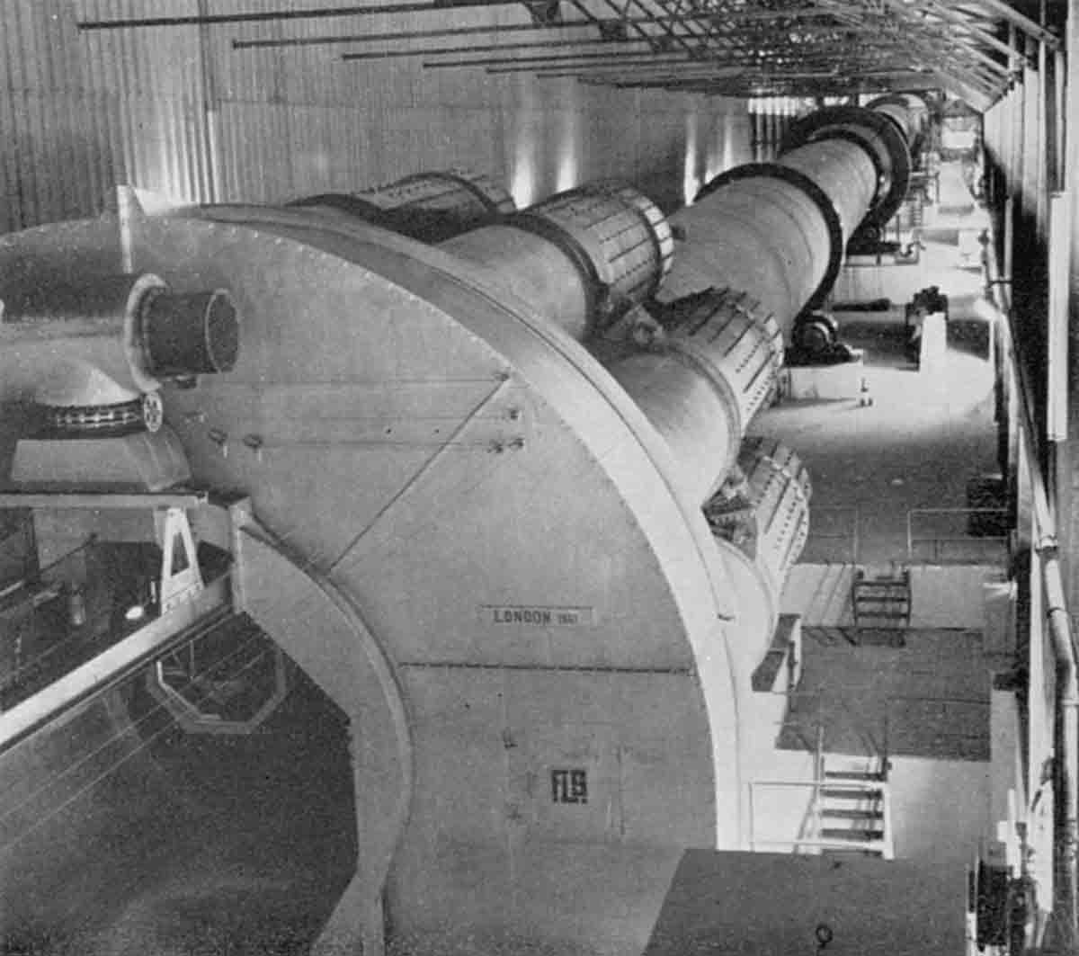 Picture: ©NERC: British Geological Survey Cat. No. P540331. North side of Kiln 5 from the coal feed platform, looking west. The wall of the crane store is to the left.
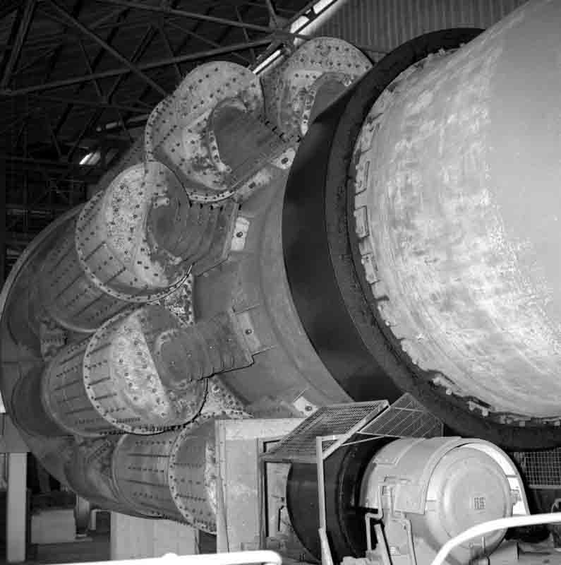 Picture: ©NERC: British Geological Survey Cat. No. P540578. Kiln 5 Unax cooler and first tyre.
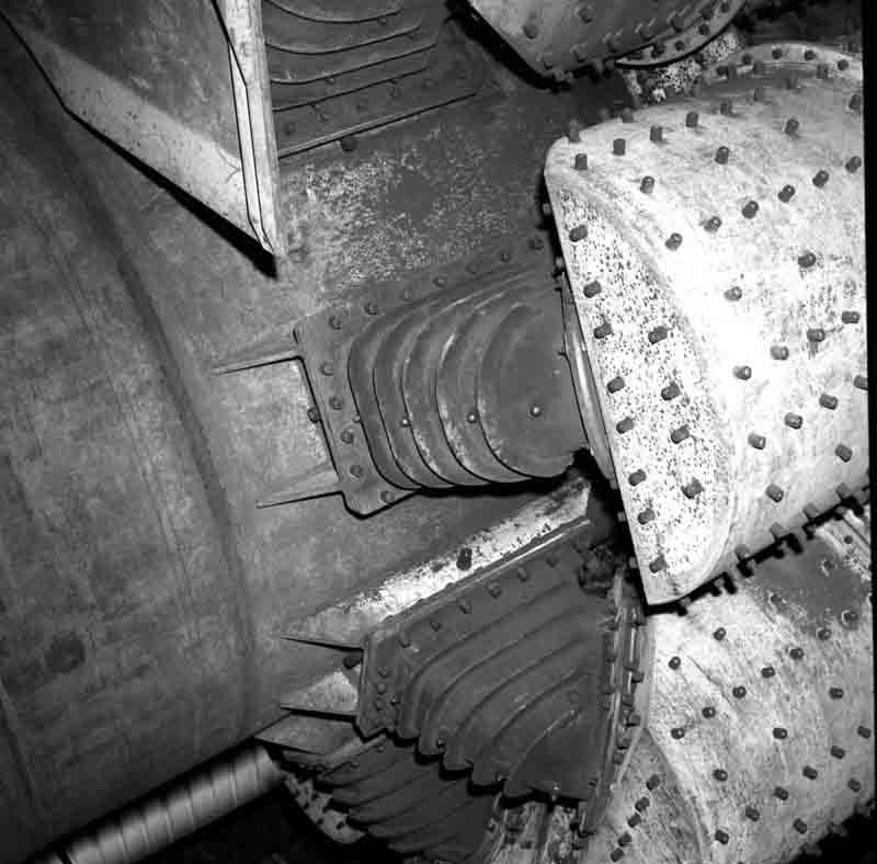 Picture: ©NERC: British Geological Survey Cat. No. P540579. Kiln 5 Unax cooler inlet detail.
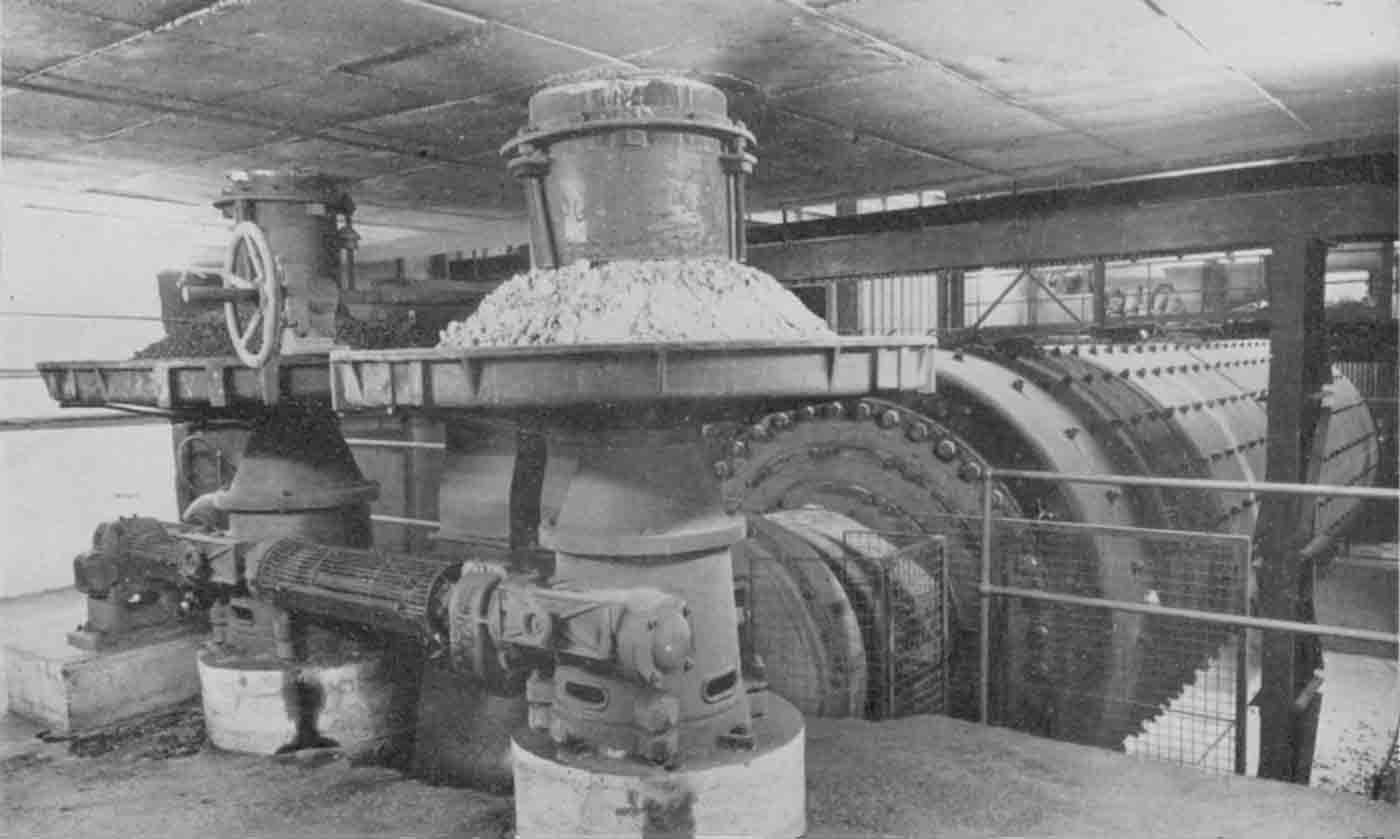 Picture: ©NERC: British Geological Survey Cat. No. P540329. Clinker and gypsum