1909-1949: Alkerden London Clay (London Clay Formation: 48-55 Ma) 560200,173100 (Swanscombe) slurried at the clay quarry and pumped to the main washmills at the chalk quarry. This was used primarily for uncallowing purposes.
1938-1970: Alluvial clay by river tanker from Cliffe 571400,177100
1938-1970: London Clay (London Clay Formation: 48-55 Ma) from Shorne Wood 568220,169070 (Shorne) slurried at the clay quarry and pumped 8.6 km along the A2 to the main washmills at the chalk quarry.
This plant was the fifth on the Thames, and became second only to Swanscombe in size during the 19th and early 20th century. It is reasonable to consider its launch as a “spoiler” orchestrated by William Aspdin when he fell out with his partners at Robins. Thomas Sturge was a prominent shipping owner at Northfleet, and his cousin's son was installed as an engineer at Robins in 1851. Bevans was subsequently erected on identical lines on what was previously a brickfield immediately adjacent to Robins on the east. Aspdin then left them to it. Sturge’s local influence allowed the plant to secure a huge swathe of chalk land to the south, boxing in the Robins reserves.
The plant seems to have made little attempt to innovate in the pre-APCM period, using wet process bottle kilns throughout, with some 3 Ha of slurry backs and drying flats, although in the later period the latter were partially heated by kiln exhaust gases. The problems of the plant's early history are discussed below. Initially there were six kilns, constructed by Sturge. Sturge leased the plant to Knight in April 1854, and by the end of 1857, two more blocks of six kilns were built. By 1864 there were 26 kilns, making 750 t/week. There was a major reorganisation in the 1870s, centralising what had previously been a dispersed layout. By the end of the century, the registered capacity was 1700 tons a week from 59 kilns, although they claimed over 100,000 tons a year in the critical years 1897-1899. In 1903, twenty kilns were demolished to make way for the rotary kilns: the rest were decommissioned by 1907. The plant was the second largest (after Swanscombe) in the new combine and, with ample raw material reserves, it was earmarked for expansion.
With the APCM takeover, a period of radical expansion commenced, characterised by somewhat chaotic improvised re-use of the cramped site, always subject to severe financial constraint. This is described at length below. Rotary kiln installation followed shortly after the formation of APCM (see article). The original eight rotary kilns were up-rated in 1906, and four more were installed before the start of WWI. The uprate was largely confined to kilns, and static kilns at the adjacent Robins, Crown and London Portland continued in use as back-up until 1910, while their raw and finish mills continued in use into the 1920s. Due to the early 1920s recession, the plant was shut down at Christmas 1921, and although kept ready for use, did not re-start during 1922-1923. On 18/9/1924, the period of paralysis ended with wholesale change of the APCM board, and it was immediately decided to re-build the plant from scratch.
The twelve early rotary kilns were cleared from October 1924 to make way for much larger kilns, the largest APCM installation of the time. Because of the plant’s cramped site, the up-rate could only be accomplished by complete shutdown and demolition of the previous kilns, which took some time, and necessitated desperate measures on the part of Blue Circle to maintain supply. The plant (in transition) was described in detail in the APCM 1924 schedule. For a short time after the uprate, Bevans was the largest UK plant, from 1927 (overtaking Swanscombe) to 1929 (after which it was overtaken by Johnsons). Kilns A1-A3 were the largest in Britain until overtaken by Johnsons A6 and A7 in 1929. With massive raw material reserves, the plant remained one of Blue Circle’s base-load operations for forty years, and was the primary exporting plant. Kiln B1 was modified for semi-wet process with a Davis preheater in 1957, but this was relatively unsuccessful, and shut down in 1967. The rest of the plant shut down in 1970, with much of the cement handling and wharfage kept in use, incorporated into the adjacent Northfleet site.
The plant never had any rail link for product, and used the river for most of its transportation, maintaining the best deep water jetty on the south bank. There was no main line rail link at all until 1915, when the loss of sea-borne coal supply led to a hurried connection of the plant to the Rosherville branch line. For much of its later history it was Blue Circle's main exporting plant. One of the Robins kilns of the 1870s (and not an earlier Aspdin kiln as claimed), much restored, is available for view and is a scheduled building. The most recent (completed 1960) kiln stack remained until demolished as part of the Northfleet clearance on 31/1/2010.
Read a description of the plant after its post-WWI upgrade in a 1928 article.
Read also a discussion of the 20th century upgrading processes.
Power Supply
The plant was originally directly driven by steam engines. A few drives were electrified with a turbo-generator in 1899. The 1904 kilns and ancillaries were operated electrically using generators driven by reciprocating steam engines, and turbo-generators were added for kilns 9-12, but the raw and finish plants continued to be driven by direct-drive steam engines. Four sets of rawmills and four sets of finish mills each had their own engine. The rebuilt plant of 1926 was all-electric and abandoned on-site generation, using purchased electric power initially from Barking, from the Kent grid in 1933 and the National grid in 1938.
Rawmills
Washmills were always used. In the early plant, the mills were on the quay, but were quite soon relocated to a point to the south of the kilns on the incoming chalk tramway. In both instances, the clay was delivered by barge at the quay in an “as dug” state. Prior to 1922, there were four washmill departments, each with its own steam engine, with a total of 9 rough mills, 9 intermediate mills and 8 finishing mills, mostly of 17 ft diameter. The 1926 plant had washmills in the quarry south of Northfleet at 561570,173980, fed with chalk brought by rail from the quarry and clay slurry washmilled at Alkerden and pumped from there (~2 km). The main washmill system consisted of two parallel lines of mills, used alternately, each consisting of a rough mill, a secondary mill, a coarse screener and a fine screener, powered by common 448 kW drives. Finished slurry was pumped 1.4 km to the plant. With the exhaustion of the Alkerden pit, clay was once again delivered to the quay, this time as slurry prepared at Cliffe, which was received in a tank from which it was pumped up to the washmills.
Sixteen rotary kilns were installed, in two stages:
Note: the history of the A-series kilns is poorly recorded. The managers' conference notes of the 1920s say there were two 110 ft long and ten 130 ft long. Jackson says there were eight 90 ft kilns, later extended to 132 ft, and four later 130 ft long. Percy Taylor, who was engineer at the plant from 1898 to 1926, says the original eight were 70 ft long, later extended to 130 ft, and a further four of 130 ft were added "between 1906 and 1913". Fletcher's notes on the APCM board minutes say that the 8 original kilns were extended from 80 ft to 130 ft and two of 120 ft were added, the other two not being mentioned. Which statements, if any, are reliable remains for the present anybody's guess. Someone out there has the plans, which do not lie. The following is a "best guess".
Kiln A1
Supplier: Fellner & Ziegler
Operated: 8/1904-5/1921
Process: Wet
Location: hot end 562066,174826: cold end 562056,174794: entirely enclosed.
Dimensions:
7/1905-12/1915: 0×1727: 1118×1727: 1118×1918: 27432×1918: 29464×2705: 36576×2705: tyres at 1651, 9271, 17374, 25451, 33528: turning gear at 14326
2/1916-12/1921: 0×1727: 1118×1727: 1118×1918: 27432×1918: 29464×2705: 39624×2705: tyres at 1651, 9271, 17374, 25451, 33528: turning gear at 14326
Cooler: rotary 48’0”× 4’10½” (metric 14.63 × 1.486) beneath firing floor
Cooler profile: 0×1486: 14630×1486: Tyres at 1524, 11278
Fuel: Coal
Coal Mill: all twelve kilns indirect fired using common coal milling system - Griffin mills?
Exhaust: direct to stack.
Typical Output: 7/1905-12/1915 65 t/d: 2/1916-12/1921 73 t/d
Typical Heat Consumption: 7/1905-12/1915 9.4 MJ/kg: 2/1916-12/1921 9.4 MJ/kg
Identical in all other respects to the extended form of A3
Kiln A10
Location: hot end 562105,174814: cold end 562093,174776: entirely enclosed.
Dates: 7/1905-8/1916: 10/1916-12/1921
Identical in all other respects to A9
Kiln A11
Supplier: ?Newell
Operated: 3/1913-12/1921
Process: Wet
Location: hot end 562066,174826: cold end 562056,174794: entirely enclosed.
Dimensions: 130’0”× 6’4½”BC / 8'10½”D (metric 39.62 × 1.943BC / 2.705D)
Rotation (viewed from firing end): anticlockwise
Slope: ?
Speed: ?
Drive: ?
Kiln profile: 0×1778: 1118×1778: 1118×1943: 28956×1943: 30785×2705: 39624×2705: tyres at 4877, 21336, 38100: turning gear at 24079
Cooler: rotary 48’0”× 4’10½” (metric 14.63 × 1.486) beneath firing floor
Cooler profile: 0×1486: 14630×1486: tyres at 1524, 11278
Fuel: Coal
Coal Mill: all twelve kilns indirect fired using common coal milling system - Griffin mills?
Exhaust: direct to stack.
Typical Output: 72 t/d
Typical Heat Consumption: 9.5 MJ/kg
Kiln A12
Operated: 4/1913-12/1921
Location: hot end 562114,174811: cold end 562102,174773: entirely enclosed.
Identical in all other respects to A11
Kiln B1
Supplier: Vickers
Operated: 23/3/1926-17/11/1967
Process: Wet: converted to semi-wet (Davis Preheater) commencing 17/09/1959
Location: hot end 562072,174827: cold end 562049,174755: from 1959 562055,174773: entirely enclosed.
Dimensions: 250’0”× 11’4”B/ 10’1½”CD (metric 76.20 × 3.454 / 3.086): shortened to 187’10⅝” (57.27 m) in 1959.
Rotation (viewed from firing end): clockwise
Slope: 1:24 (2.388°)
Speed: ?
Drive: ?
Kiln profile:
1926-1959: 0×2540: 3962×3454: 15545×3454: 16764×3086: 76200×3086: tyres at 2134, 17831, 33071, 50521, 67970: turning gear at 35052
1959-1967: 0×2540: 3962×3454: 15545×3454: 16764×3086: 56407×3086: 57017×2400: 57267×2400: tyres at 2134, 17831, 33071, 50521: turning gear at 35052
Cooler: rotary 92’0”× 9’10¾”/ 8’10¾”/ 6’3¾” (metric 28.04 × 3.016 / 2.711 / 1.924) beneath kiln
Cooler profile: 0×3016: 6325×3016: 7557×2711: 12967×2711: 15418×1924: 28042×1924: tyres at 5664, 22022: turning gear at 19888
Fuel: 1926-1959 Coal: 1959-1967 Oil
Coal Mill: as installed, kilns B1-B4 were indirect fired, fine coal being supplied by six British Rema ring-roll mills.
Exhaust: originally direct to stack. An ID fan was introduced in the early 1930s, and a pair of parallel electrostatic precipitators was added in 1960.
Typical Output: 1926-1931 369 t/d: 1932-1959 374 t/d: 1959-1967 419 t/d
Typical Heat Consumption: 1926-1931 8.66 MJ/kg: 1932-1940 8.03 MJ/kg: 1941-1959 7.17 MJ/kg: 1959-1967 5.00 MJ/kg
Kiln B2
Supplier: Vickers
Operated: 22/6/1926-30/11/1970
Process: Wet
Location: hot end 562087,174823: cold end 562064,174750: entirely enclosed.
Dimensions: 250’0”× 11’4”B/ 10’1½”CD (metric 76.20 × 3.454 / 3.086)
Rotation (viewed from firing end): clockwise
Slope: 1:24 (2.388°)
Speed: ?
Drive: ?
Kiln profile: 0×2540: 3962×3454: 15545×3454: 16764×3086: 76200×3086: tyres at 2134, 17831, 33071, 50521, 67970: turning gear at 35052
Cooler: rotary 92’0”× 9’10¾”/ 8’10¾”/ 6’3¾” (metric 28.04 × 3.016 / 2.711 / 1.924) beneath kiln
Cooler profile: 0×3016: 6325×3016: 7557×2711: 12967×2711: 15418×1924: 28042×1924: tyres at 5664, 22022: turning gear at 19888
Fuel: 1926-1959 Coal: 1959-1967 Oil: 1967-1970 mixed firing, 22% Oil
Coal Mill: see B1
Exhaust: originally direct to stack. An ID fan was introduced in the early 1930s, and a pair of parallel electrostatic precipitators was added in 1960.
Typical Output: 1926-1931 359 t/d: 1932-1959 368 t/d: 1959-1967 359 t/d: 1968-1970 321 t/d
Typical Heat Consumption: 1926-1931 8.72 MJ/kg: 1932-1940 7.96 MJ/kg: 1941-1959 7.24 MJ/kg: 1959-1967 7.88 MJ/kg: 1968-1970 8.19 MJ/kg
Kiln B3
Operated: 16/8/1926-30/11/1970
Location: hot end 562101,174818: cold end 562078,174745: entirely enclosed.
Typical Output: 1926-1931 357 t/d: 1932-1959 375 t/d: 1959-1968 362 t/d: 1968-1970 324 t/d
Typical Heat Consumption: 1926-1931 8.85 MJ/kg: 1932-1940 8.06 MJ/kg: 1941-1959 7.16 MJ/kg: 1959-1968 7.72 MJ/kg: 1968-1970 8.17 MJ/kg
Identical in all other respects to B2
Kiln B4
Supplier: FLS
Operated: 20/1/1928 - 30/11/1970
Process: Wet
Location: hot end 562114,174808: cold end 562088,174725: entirely enclosed.
Dimensions (from cooler ports): an enlarged backend was installed in 1936, removed 1954?
Read the description of the plant after its post-WWI upgrade in the 1928 article.
The following is a transcript of an anonymous article from the Gravesend and Dartford Reporter of 24th January 1880, and describes Bevans at a time when it was probably the world's biggest cement plant, but was being rapidly overtaken by White's plant at Swanscombe. After this date, the plant entered a long period of quiescence, continuing the primitive manufacturing techniques described here, ended only when the firm became part of APCM in 1900, after which rapid updating and expansion once more took place.
I have slightly modified the text to remove some of the more irritating prolixities of the writer's florid style, and to break up some of the epic-lengthed sentences.
CEMENT MANUFACTURING Messrs. Knight, Bevan & Sturge's Works
The industries of the neighbourhood of Gravesend and Northfleet are by no means so numerous and diversified as those of many districts, but they are sufficiently large to provide employment for an immense number of people, and are the means of support to hundreds of families. The natural products of the district have been turned to great advantage in this respect, and the proximity to the river with which chalk is found in abundance has led to a vast trade being done on both sides of the river in products either in whole or part manufactured from this material. Thousands of tons of chalk are weekly carried away by ships, as ballast, to all parts of the United Kingdom and many foreign countries, where it is converted into lime, cement, and other articles of great service in the building trade (Note A1).
That some portions of these industries have been carried on for generations is evident by the vast excavations which have been made in the cliffs all the way from Gravesend to Northfleet, and far beyond that improving and extending town (Note A2). Some of these quarries have long been disused, and Rosherville Gardens, with its miles of walks, now occupies the site of what once was a scene of busy industry, whilst further to the west, almost a little town (Note A3) has been erected in a disused quarry, and long rows of houses occupy a portion of the site which was once encumbered by millions of tons of chalk. Very many years ago, men of enterprise and genius turned their attention to these white cliffs, and after patient investigation, found that the chalk of which they were composed could be wrought to immense advantage, when mixed with other ingredients, and carefully manufactured. And thus Portland cement came to be manufactured on the Thames, and has now become so much in demand that its production finds employment for the bulk of the population of Northfleet, Greenhithe, and the district extending inland for miles from those places, besides having given rise to the town of Grays, on the Essex side, the greater part of whose inhabitants owe their support to this manufacture and its kindred industries. Seeing then that chalk is so great a factor in the well-being of thousands of people in our neighbourhood, it may be interesting to give a slight description of one of these manufactories, and that not by any means the smallest, in the district.
A little over a quarter of a century ago, when the allied armies were being decimated by cold, disease and battle, before the walls of Sebastopol, and when the newspapers of England were full of the daring deeds of our countrymen abroad, three gentlemen in Kent were founding an industry, which has been fraught with far more good to the people of this country than ever was achieved by the Crimean war (Note A4). Mr J M Knight, then residing at Rochester; Mr Thomas Bevan, a resident of Northfleet; and Mr Sturge, a member of the Society of Friends; became partners, and in 1854 founded and commenced the works which have culminated in the gigantic establishment now known as the Portland Cement Works of Messrs. Knight, Bevan and Sturge, and which extend over so many acres of ground between the river Thames on the north, and the North Kent branch of the South Eastern Railway on the south. It is these works that we will now endeavour to give a slight description of, and also the process of manufacture of that Portland Cement which is famed throughout the whole world.
Bevans plant around 1860. The exact date of the image is uncertain, but the plant was shown in this form on the OS map surveyed in 1863-4, and there was little change in the main features during the rest of the century. Some of the kiln blocks were still present at the time of the 1924-8 rebuild.
Looked at from the River Thames, on a most advantageous point of which they abut, the works do not present much that is beautiful or picturesque. Extensive wharfages and docks are seen on the banks of the river, and behind these are long ranges of substantial buildings used as warehouses and store-rooms. Then again, further in the rear, are the immense drying kilns and other buildings which we shall visit to detail, and all erected on ground from which chalk has been quarried. Further back again, on a portion of the yet unwrought cliffs, are a series of large tanks or reservoirs, the whole being backed up by the town of Northfleet, conspicuous amongst whose buildings is the handsome institution known as the Factory Club, erected a short time ago by Mr. Thomas Bevan, for the comfort. convenience and education, not only of his own work-people but for all those residing in the neighbourhood who care to share in its advantages. And we may here state that, although the firm is yet that of "Knight, Bevan and Sturge", the first and last of these original partners have retired from the business, Mr. Knight having left it about four years ago, and it is now entirely conducted by Mr. Thomas Bevan and his son, with the assistance of Mr. Weeks as manager, Mr. Williams as chief clerk and cashier, and a number of other gentlemen as heads of departments (Note A5).
After a visit to the well-appointed suite of offices, we notice close by several barges, from one of which is being unloaded a substance which is cut up by spades, much as butter is cut in a grocer's shop. It is then lifted on to waggons, which are drawn by powerful and handsome horses into the interior of the works. This substance is blue clay, dug from the marshy lands on the banks of the Medway, where it is found in beds varying in thickness from six to eight feet. This clay is a most valuable ingredient in the manufacture of cement, in the process of which it is mixed with the chalk in certain proportions. Following one of these waggons we soon come upon a scene of busy industry. There are tramways in all directions, and to one unacquainted with the business, general confusion seems to prevail. Men and horses are moving about here and there, the latter drawing waggons loaded with chalk or clay; the steady stroke of steam engines is heard above the rattle of hundreds of cooper's hammers, and the noise made by numerous steam saws.
Passing all these, however, for the present, we are conducted to a small locomotive engine, appropriately named after Stephenson's first engine on the Liverpool and Manchester Railway, "The Rocket"; for mounting this, to which was attached half-a-dozen empty waggons, we were soon shot through a couple of tunnels of considerable length, emerging in an immense quarry to the south of the London-road (Note A6), and where the first process towards the manufacture is carried on. High up on the cliffs, from which the soil had been removed, were a number of men, each armed with a long bar of iron, shod at one end with steel, and being sharp-pointed. These are called "pitchers", and with them the chalk is broken away from the cliff. Tramways are laid to the face of the cliff in more than a dozen directions, and where these abut, passages have been cut in the chalk, narrow at the bottom, but becoming wider above, and much resembling a large hopper cut in two. As the chalk is loosened by the men at work above, it rolls down, and through these passages, into the waggons, which, when full, are drawn away by horses on to the main line, ready to be attached to the locomotive, which takes them away in trains (Note A7). The position of the quarrymen, standing on the narrowest of ledges, 40, 50, or even 60 feet high, seems to be one of great danger; but so accustomed are they to the work, that they feel perfectly at ease, and an accident by falling is of rare occurrence. In some parts of the quarries, huge mounds of material are left standing, and look like so many gigantic land-marks, left there to mark for future generations the depth of the excavations that have been made around them. This, however, is not their object. They are left there because the material of which they are composed is of no use. By some freak of nature these mounds, which are of fine gravel, have been pushed through the chalk measures, and they are known as "potholes". As the chalk is dug away, and the bottom of the bed reached (Note A8), the ground is again covered with the soil which has to be removed from other cliffs, and so good and productive land made.
Returning with a train of loaded waggons, with which the little engine struggles along as if almost unequal to the task, we soon emerge again on the north side of Northfleet, and in the busy yard above referred to. As soon as the train is brought to a stand, horses are attached to each of the waggons, which by means of turn-tables and sidings are conveyed to the sides of the washers, each one being passed over a registering machine, by which they are also weighed. Should any waggon be under the standard weight it does not register, and therefore the quarrymen do not get paid for it, hence it is their interest, and one which they rarely neglect, to send all waggons up to the full weight (Note A9). The washers are a series of circular tanks, which very much resemble the "mash-tubs" of a large brewery, for in each of them is a revolving machine, with toothed points. These machines are driven by powerful horizontal engines, of which there is one to each set, and the clay and chalk being thrown into these in proper quantities, and mixed with water, are soon reduced to a pulp of about the consistency of thick gruel (Note A10). When this is accomplished, the material is lifted by powerful pumps into one of the reservoirs above mentioned, on the top of the cliff, and there allowed to settle. The water is then drawn off, and what is left is a solid wet mass, known to the initiated as "pug".
This "pug" is then cut out, and wheeled on to the drying floors, which are of immense extent, and situated over the burning kilns, the heat from the latter being utilised for this purpose. Whilst in this stage of the manufacture, the material becomes of a creamy colour, and when sufficiently dried, it is put into the kilns or ovens. These are very numerous, and of great size, and when one has been filled, it is sealed up with bricks and cement, and a fierce coke fire is lighted under it, which gradually extends all over the kiln, the whole becoming of a white heat. This process continues for about three days, and then the kilns are opened, and the calcined contents allowed to cool. As soon as it is cool enough, the material is dug out in large unshapely masses, and taken to the crushers, through two sets of which it passes, being reduced to bits about the size of beans. By a series of mechanical elevators, it is carried on to a lofty flooring, when it is put into huge hoppers, and thence passed to the stones. These are immense French burr mill stones, put together in irregular pieces, and shod with massive iron tyres, and by their rapid revolution and great weight they grind the material as fine as powder, thus completing the process of manufacture. Some idea of the pressure which is brought to bear upon the material in this last process may be gathered from the fact that the cement is rendered so hot, that it is with difficulty anyone can bear their hands in it.
From the mills the cement is conveyed to the warehouses, which are buildings of immense size, capable of containing many ships' cargoes, and here the cement is placed in barrels or bags, ready for shipment. Before, however, entering upon this, we must once again return to the yard, and visit the cooperage, which is one of the most interesting features about the establishment. Almost concealed by heaps of timber, are a series of low buildings, from which almost every variety of sound issues during working hours. In these buildings, the work of making casks is carried on in a wholesale manner. The timber for this purpose is brought to the premises all cut square. This is first taken to the saw mill, where nearly all kinds and sizes of saws are whirling round with immense velocity, threatening to cut anything to pieces which is brought in contact with them. The staves being made of proper length, are applied to a saw, which cuts the ends to the proper bevel to fit them to the shape of a tub, when they are loaded on to a barrow by boys, and wheeled to the next department. At another machine two or three square pieces of wood are placed under a cutter, and instantly shaped to the end of a barrel, these also being placed in sets, and wheeled away. A number of staves are then placed together in a most ingenious machine, by which they are compressed together at one end, to enable the first hoop to be put around them, and to which they are slightly fastened. Scattered about the buildings are a number of upright circular grates, in each of which a bright coke fire is burning; and over one of those grates the frame of the tub is put, remaining there until the staves are bent and drawn by the heat, and until the wood becomes in a blaze. Then it is quickly removed, a wet brush being run around the interior to put out the blaze, and it is taken away by a cooper, who with the most marvellous rapidity puts on the remaining hoops, both of withe and iron, places in one end fast, and fits the other, and then the work is complete, the finished tubs being carried away to the warehouses or stores as fast as they are made. It is truly wonderful to witness this part of the works. By the aid of the most ingenious machinery, and a proper distribution of labour, that which at first seems chaos is speedily reduced to order, and an idea will readily be formed of the magnitude of the coopering operations when it is stated that the regular day's work is 2,000 barrels, each capable of containing 400 lb of cement, and during busy seasons as many as 2,200 have been turned out in the working day.
Whilst in this locality, a peep into the stores disclosed to view a stock of almost every kind of article used on the premises, including hogsheads of oil, coils of rope, string, shovels, buckets, skeps, screws, nails and a hundred other things, including immense piles of paper, some of which is waterproof. This last is used in the packing process, and that brings us back to the warehouses, where the barrels we have seen made are quickly lined with paper, filled with cement, had their ends put in, and then being stamped with a pyramid, the trade mark of the firm, they are rolled away, ready for shipment. At the several jetties and wharves, just outside the warehouses, barges can lay alongside, three or four deep, and be loaded at any state of the tide. This is accomplished by self-acting cranes, by which a couple of barrels at a time are lifted from the wharf, and lowered swiftly into the holds of the vessels, where they are rapidly stowed away, the cargo of a barge being from 500 to 600 barrels. By these barges the bulk of the produce of the manufactory is conveyed to London, where it is shipped to all parts of the globe. A large quantity, however, for home consumption, is shipped on board larger coasting vessels, and carried direct to its destination. The firm owns a very large number of barges, and employs upon the works between 700 and 800 people, besides requiring the services of nearly thirty horses. In addition to the departments already mentioned, there is a fitters' and mechanics' shop, replete with all the usual lathes, drills, planes, &c., and in which all repairs are accomplished, both to tools and machinery, and in which a considerable portion of them are made. It will thus be seen that this one establishment forms no mean part of the support of Northfleet, and that a visit to it is one of the greatest interest.
The following is a transcript of an anonymous article that appeared in Cement and Cement Manufacture, 1, 1928, pp 21-28, 48-55, 69-74. It is believed to be out of copyright. It describes the Bevans plant immediately after its 1920s re-build, and represents what was considered the best technology in the immediate post-WWI period. Although many of its features were rapidly superseded, many others remained standard for decades. The minute detail in the description of the electrical system is understandable in view of the fact that plants prior to this were only minimally electrified. A few errors and units have been tidied up.
Values of imperial units (as of 1928) used in the text (alphabetical order): 1 inch = 25.399956 mm: 1 ft = 0.30479947 m: 1 yard = 0.91439841 m: 1 acre = 0.40468424 Ha: 1 cubic ft = 0.0283167 m3: 1 gallon = 4.5460756 dm3: 1 lb = 0.45359234 kg: 1 cwt (hundredweight) = 50.802342 kg: 1 ton = 1.01604684 tonne: 1 HP (horse-power) = 0.7456998 kW: 1 psi (pound-force per square inch) = 6.89478 kPa.
Bevans Cement Works, Northfleet
The Bevans Works of the Associated Portland Cement Manufacturers, Ltd., at Northfleet, Kent, have recently been reconstructed and enlarged, and are now claimed to be the largest and most up-to-date cement works in Europe (Note B1). The capacity is stated to be about half-a-million tons of cement a year.
Historically, the works date back to the dawn of the cement age; in the first half of the last century, when Joseph Aspdin's son erected his first kiln on a portion of the site, and some of the original kilns are still preserved (Note B2). It is not the present intention, however, to review the history of the works, but rather to describe it as it is today.
The geographical advantages of its position are exceptional. Situated on the great Thames Waterway with solid chalk foundations down to deep water, it has shipping facilities of a unique character.
Those who are familiar with the geology of Kent know the almost inexhaustible supplies of chalk and clay which abound in this neighbourhood, and it is not surprising to learn that the Bevans management are free of all worry as to future supplies of the necessary raw materials.
The clay now being used is dug by steam navvy from a deposit of London clay about two miles away (Note B3), and is immediately tipped into washmills and reduced to a thin slurry with about 60% of water. This fluid clay is then pumped to storage tanks at the (main) washmill, which is in the chalk quarry about half-way to the works. Here the chalk is dug by an electrically-operated navvy weighing 70 tons, which digs 3½ cubic yards of chalk at one bite and deposits it in 10-ton railway wagons, trains of which are hauled by steam locomotives a short distance to a combined electric hoist and tippler which picks them up bodily and tips their contents into the first of a series of heavy washmills.
The required proportion of clay slurry is pumped into the same mill from the storage tanks adjoining, and the two materials are then mechanically mixed while the chalk is being reduced to a very fine state of subdivision by the revolving harrows in the washmill. The resulting mixture of chalk and clay slurry contains about 40% of water and leaves the first washmill when it is fine enough to pass through the surrounding screens, passing in succession through three other mills, each of which has finer screens than its predecessor. The slurry when it leaves the final mills goes to mixing and storage tanks adjoining where its composition is again checked (Note B4).
It is pumped nearly a mile through two pipe-lines to the final series of storage tanks at the works. These tanks, of which there are six, are situated immediately at the upper end of the rotary kilns, and the slurry gravitates from them to the boots of the four bucket elevators which deliver it at sufficient height to enable a gravity feed to the rotary kilns. The slurry storage and mixing tanks are of standard type throughout, 66 ft. in diameter and 11 ft. deep, and are continuously agitated (Note B5).
The coal used by the works is all sea-borne and is received alongside the eastern extremity of the deep-water jetty, where it is unloaded by electric grab cranes and transported by a belt conveyor system to storage bunkers ashore, situated at the east end of the kiln house. A complete system of extractors beneath the bunkers facilitates the isolation or mixing of fuels as the exigencies of service demand. The pulverised fuel for kiln firing is prepared by six large high-speed vertical mills housed between the coal storage bunkers and the kiln plant.
The powdered fuel is stored in self-trimming hoppers, from which it is continuously circulated along the firing floor, surplus being returned to the storage hoppers. Variable speed extractors tap the coal supply opposite each kiln at the firing end. There are four rotary kilns of the latest design and construction, the loaded weight of each unit being in the region of 800 tons. Three of them are 250 ft. long with separate coolers (Note B6); the fourth is 294 ft. long, and embodies a combined cooler arrangement consisting of a series of small tubes arranged around the periphery of the firing end of the kiln (Note B7). All have enlarged burning zones and are direct driven through gearing from the motor to the girth ring.
The cooled clinker from the kilns is conveyed by band conveyors and bucket elevators to large reinforced concrete storage hoppers, whence it is delivered by gravity to the grinding mills immediately beneath. These mills are of the "combination" type, consisting of a long steel tube 36 ft. long by 7 ft. in diameter, divided into compartments.
The first compartment into which the clinker is delivered is charged with steel balls of 4 in. to 2½ in. diameter. The coarse grit from this compartment passes through a slotted diaphragm into an intermediate compartment, where it is further reduced by balls of 2½ in. to 1½ in. diameter, and then passes to the final stage, where it is reduced to an impalpable powder by smaller grinding media. There are seven of these large mills, five of which are driven by slow speed synchronous motors each taking 750 h.p. and the remaining two being driven through double helical gearing and are rated at 525 h.p. (Note B8)
The cement is then delivered to a Fuller Kinyon pumping installation, which delivers it by means of compressed air into the battery of twelve storage silos, the lift being no less than 102 ft. This method of conveying cement is quite new to this country and a description of the installation may be of interest. The pump itself is a very simple piece of apparatus, consisting of a cylindrical barrel in which a motor-driven screw rotates at fairly high speed. Near one end the cement is admitted into the barrel, and the screw conveys the material forward. It may be noted that the pitch of the screw is diminishing, hence the cement fills the barrel as a piston towards the end of the screw, At the end of the barrel is a ring with an annular space (between the ring and the cylinder walls) through which numerous small holes or ports are drilled at an angle of 45 degrees towards the direction of flow. Compressed air is applied at this point, and maintains the velocity of a stream of air (and cement) towards the open end of the pipe system. The cement is mixed with air, and the transmission of the "fluid" is continuous, but over and above the continuous stream there are more-or-less regular periodic " gusts". The lift is not accomplished by alternate layers or pistons of cement and air, as many conjecture. Perhaps the most accurate picture of the rising main would be to visualise two centrifugal pumps putting two classes of liquid through the same discharge pipe, one (say) heavy oil or tar, and the other water; both would emerge continuously with occasional gusts of the heavier fluid. If the gust were regular the analogy would be complete.
A wharf is provided for the reception of steamers discharging gypsum for slowing the set of the cement at the west end of the river frontage; after unloading, the material is conveyed by an elevated belt conveyor system to unit hoppers constructed in the clinker store immediately over each combination mill.
The twelve cement storage silos are built of reinforced concrete and are capable of holding 22,000 tons of cement. They are subdivided with central stairways to facilitate accurate sampling of the bulk.
The cement handling and packing plant and the wharf facilities at this works are exceptionally interesting, and it is proposed therefore to describe them in some detail (Note B9).
The main scheme consists of a deep-water concrete jetty some 600 ft. long and capable of berthing the largest steamers (up to 15,000 tons) at all states of the tide, flanked by several unit packing plants each independently fed and operated. The jetty itself stands away from' the plant, thus giving outside and inside accommodation for craft, and is equipped with five high-speed heavy duty electric luffing cranes. These cranes travel along the jetty as required and can take slings of cement from the shore plant and deliver it straight into the steamer's hold.
Adjacent plants feed the jetty by means of a circular railway track, thus supplementing the plants immediately facing the jetty. By this means a very high rate of loading can be maintained. When it is considered that some 10,000 tons of cement have to be dispatched each week, and occasionally as much as 12,000 tons, in spite of rain, fog, and other delays incidental to shipping, the necessity for such elaborate plant and organisation will be appreciated. Several complete and independent systems exist for extracting cement from the silos and conveying it to the various packing plants.
Ancillary to the factory proper there is a complete organisation of cooperages, steel-drum factory and sack plant, which supply the many thousands of packages required each day for the large tonnages shipped overside (Note B10).
Special attention has been given to the important question of continuously sampling the product at all stages of manufacture.
Electric power for motive purposes is obtained in bulk from Barking (Note B11), at a pressure of 33 kV, 3-phase, alternating current. It is stepped down to 3,000 V at the main receiving station. As a general rule all motors of 100 h.p. and upwards are on the 3,000-V circuit, smaller units are fed from a 500-V distribution. Precautions are taken in the switching on and off of the larger units to preserve an even load factor, as there are some four hundred electric motors in the works ranging up to 750 h.p. each.
A complete organisation exists for "Safety First", welfare, and recreation, including a large club, swimming baths and a sports ground adjacent to the works.
Electrical Equipment.
The electrical plant as a whole has one or two notable characteristics; the motors are generally of the squirrel-cage type driving, where the starting conditions are heavy, through centrifugal clutches. All motors, including those for the tube mills, are mounted on roller or ball bearings. The cable system is totally enclosed right up to the points of application, and the smaller wiring (lighting, etc.) is in conduit, with ironclad switches and fuses, reducing risks of failure and shock to a minimum.
The power for the works is transmitted from Barking at 33 kV by means of underground cables, and is delivered at the supply company's sub-station at the washmills. The supply is controlled by six " K " type switches, with a breaking capacity of ¾ million kVA each, and passes on to two banks of three single-phase transformers of 2,500 kVA capacity each, i.e. two 7,500-kVA groups, which step the pressure down to 3 kV. These transformers are situated between the supply company's sub-station and the works receiving sub-station. In the latter are situated the power company's 3,000-V control switches, also of " K " class, and on which is accommodated the metering equipment. The bus-bars from these two switches are continued and connected to ten sets of truck-type gear, the switches in which have each a rupturing capacity of 100,000 kVA. This switchboard controls two feeders to the washmill sub-station, six feeders to the main works sub-station, one clay mill feeder, and one metering panel.
Throughout the factory the switchgear and the distribution system have been so arranged that the supply to the different processes of manufacture is controlled from the two sub-stations, one at the washmill and the other at the main works. This also permits of the metering of the unit consumption of each section from these two main points. The factory load is 6,000 kW; as a result the electrical stresses on switch and control gear when operating under short-circuiting conditions are heavy, but these are considerably reduced by the cable system adopted.
For the washmill sub-station the basement of one of the two main motor-houses has been utilised. The position is at the centre of the load dealt with, and has resulted in an economical lay-out of the feeder and distribution cables. The sub-station is equipped with a 3-kV switchboard, one 750 kVA 3,000/500 V transformer, a 500-V switchboard, and a 20 kVA 500/110 V lighting transformer with switchgear. Six truck-type units comprise the H.T. switchboard and control the two incoming feeders from the main sub-station, the H.T. side of the transformer, two feeders to the two main motor houses, and a feeder to the quarry giving a supply to an electric navvy. The 500-V switch-board is built up of seven pedestal iron-clad units of the draw-out type, one unit controlling the L.T. side of the transformer, one the lighting transformer, and the remaining five distributors to fuse pillars or boards from which the supplies to motors are taken.
In each of the two main motor houses are installed two 200 h.p. squirrel-cage motors, one driving a roughing mill and the other a line of finishing mills. The machines, fitted with centrifugal clutch pulleys and controlled by heavily-rated auto-transformer starters, totally enclosed and designed for operation by unskilled labour, effectively deal with the heavy starting duty imposed upon them. The roughing-mill motor is also fitted with barring gear driven through a special worm reduction gear by a high-torque motor, which facilitates cleaning out and overhauling the mill.
The chalk, quarried by a 3½ cubic yard electrically-driven navvy fitted with a straight A.C. equipment, taking an average load of 150 kW and peak loads of 230 kW, is conveyed to the washmill in trains made up of standard gauge 10-ton trucks. Here the wagons run on to the electrically-driven tippler hoist, which is controlled by a fully automatic equipment; the operation of the starting button raises the truck about 40 ft. and then empties its contents into a hopper feeding the two roughing mills, afterwards lowering it to rail level. The tippler is fully protected by limit and emergency switches, and in addition a stand-by hand-controlled equipment can be put into operation by the throwing over a dual control change-over switch. For a given quantity of chalk tipped into the washmill a certain amount of clay slurry is required. The slurry, stored in mixer tanks 30 yards distant from the washmills, is elevated and runs by gravity into the roughing mills. The elevator is driven by a 20 h.p. motor and is controlled by a direct switching contactor starter fitted with an adjustable timing device which can be set so that the elevator on operating the start button runs for a predetermined time corresponding to the amount of clay slurry required. The elevator is controlled at the tippler.
The clay slurry is obtained from the clay plant situated a mile from the main washmill, the power being transmitted to it at 3,000 V by an overhead line. The transmission line is tapped about a quarter of a mile from the washmill for supplying a 75 kVA transformer giving current at 500 V to two electrically-driven centrifugal pumps. The line tapping is controlled by a pole-mounted oil-switch fitted with overload protection, whilst the pumps are controlled by automatic starters remote-operated from the washmills. The main units at the clay plant are three washmills and a line of pumps for pumping the slurry to the mixers situated near the washmills; each unit is driven by a 100 h.p. 3,000-V squirrel-cage motor fitted with a centrifugal clutch and controlled by an auto-transformer starter. The equipment is simple and robust and gives no trouble although operated by very unskilled labour (Note B12).
At the main washmill for pumping the finished slurry through the two pipe lines to the main works six three-throw pumps have been installed, each driven by a 50 h.p. squirrel-cage motor fitted with a centrifugal clutch coupling driving the pumps through reduction gears. The motor equipments are erected in line in the pump house whilst the starters, of the star-delta type, are mounted in a separate control room which also houses eight direct switching starters for 12 h.p. motors each driving a 66-ft finished-slurry mixer. The separate control house for the control gear is a desirable feature on a washing plant.
Power is transmitted at 3,000 V from the supply Company's sub-station, a distance of three-quarters of a mile to the main works, by six 0.4 sq. in. feeders drawn through a six-way earthenware duct, inspection and draw pits being provided every 200 yards. The feeders operate in parallel and feed on to the bus-bars of a 15-panel H.T. switchboard in the main works sub-station. The sub-station also contains five 750 kVA 3,000/500 volt transformers, a 17-panel L.T. switchboard, and a 30 kVA 500/110 volt lighting transformer bank with switchgear. The H.T. and L.T. boards are built up of truck type and ironclad pedestal units respectively, similar to those used at the washmill sub-station. The H.T. and L.T. switchboards are at each side of the sub-station facing each other with the transformers between them, the lay giving easy control of the distribution system which has been carried out on similar lines to that described at the washmill. Points of interest in connection with the sub-station are that the 5,000-V incoming feeders are fitted with parallel protection induction-type relays operating on the definite minimum-time-limit principle, and that the metering panel instruments include an indicating kW meter and power-factor meter showing the value and power factor of the factory load. These instruments are energised through pilot cables from potential and current transformers installed at the Supply Co.'s sub-station. A maximum demand alarm relay which operates a Klaxon horn when the load exceeds a pre-arranged figure is also provided.
In general the motor equipments call for no special comment. The six coal mills are each driven by a 75-h.p. vertical-spindle squirrel-cage motor fitted with a clutch pulley. The grinding mill motor house contains the motor units previously mentioned which total 4,750 h.p., and the building is ventilated by clean washed air under pressure.
The Buildings.
Naturally the buildings, silos, washmills, and other structures are practically all constructed of reinforced concrete, and in addition there have been many minor applications of reinforced concrete, such as elevator towers, hot-air flues, etc., described in the following notes. Rapid-hardening Portland cement (Note B13) was used almost exclusively for all the reinforced concrete, and although a large proportion of the work was done in extremely cold weather it was nearly always possible to get a lift on wall work every day.
Clinker Store - One of the largest and possibly the most interesting, structure is the clinker store,.
The Bevans plant was one of the earliest and biggest making Portland cement, and, built adjacent to William Aspdin'sNorthfleet plant, is intimately tied up with the development of Aspdin's career. An account of the origins of the plant is closely tied to the biography of Thomas Sturge. Unlike most of the dramatis personae of the cement industry, as a prominent Quaker and Abolitionist, a lot has been written about Sturge. One would imagine that the wealth of information would make it easy to tie down the chronology of the plant, but this is far from the case. I recently stumbled across a few newspaper articles that forced a re-assessment of my own account, and to try to resolve conflicting information, I did more research on the period 1840-1870.
My original account made heavy use of that of Francis. Francis stretched his account to four pages (163-166) despite saying very little about the plant. He says "few details of the firm's activities have survived", by which he means that he - personally - has found few details of the firm's activities. Among other things, Francis' aversion to the use of the first person (which I don't share) motivated me to begin this website. He does mention a plan dated 1869 which contained a number of layout details. Although he doesn't explicitly say so, I (and others) interpreted this as meaning that this was the total extent of the plant at the time. I subsequently got a copy of the plan and found this assumption to be wrong. Francis begins by giving Thomas Sturge's family background. See my summary biography.
William Aspdin began making Portland cement on leasehold land immediately adjacent to the west in 1846. Presumably Aspdin was in contact with Sturge at an early stage, perhaps to lease further chalk reserves. One would imagine that Sturge was immediately sceptical about the flaky Aspdin (Aspdin's lifestyle could not be described as Quakerish) and kept him at arm's length. Aspdin's relationship with his financial backers followed the familiar trajectory; his collaborators gradually became aware of systematic fraud. By 1851 he was also being accused of "combining and confederating with persons unknown to wrong and injure his partners". Francis quotes Aspdin as saying that he "wished the partnership to the devil and would screw it up" (Note C1). It is clear that Sturge had decided to build his own cement plant, and had obtained help from Aspdin in designing it. This not only competed with the existing plant, but also permanently prevented its expansion eastward. A letter written by Aspdin in December 1851 stated that Mr Sturge has commenced building his plant (Note C2).
Sturge's lands consisted of the Orme and Hive estates, which were tracts extending from Ebbsfleet to the south of the High Street (then called Bow Street) northward to the waterfront, and from College Lane on the west to Lawn Road and the church to the east. The North Kent railway was later (1849) constructed across them. The boundary between the two tracts ran along Hive Lane. Sturge and his brother (and his elder sister Esther) moved permanently to Northfleet in 1842, taking the then partially-constructed Northfleet House south of the High Street.
Francis says the initial cement plant was operational "by 1853 if not earlier". Subsequently, the company of Knight, Bevan and Sturge was set up. The original project was set up by a partnership of Thomas, George and Alfred Sturge. Francis says that they were all in their sixties and needed "younger blood". In fact, in 1853, Thomas was 66, George was 56, and Alfred was only 31. Alfred was not a cousin but a son of their cousin Thomas Marshall Sturge (b 30/7/1791: d 25/1/1869) who was the son of Thomas Senior's brother Joseph. Alfred was an engineer, and was undoubtedly the main designer and operator of the plant.
John Messer Knight and Thomas Bevan (b 26/11/1829 City of London: d 1/3/1907 Stone) were members of local Quaker families. They arrived on the scene in 1844. Evidently, having set up the plant, Thomas and George preferred to retire, so a partnership was set up between Knight, Bevan and Alfred Sturge (b 19/10/1822 Olveston, Gloucs: d 21/11/1859 Northfleet), and the plant was leased to them for 99 years from July 1854. Thomas Sturge and his sister continued to live at Northfleet House until his death in 1866. Now detached from manufacture, he was free to indulge in environmental complaints, and in 1857 he began a case against Knight, the reporting of which throws light on the development of the plant. The case was reported in several newspapers.
In the Maidstone Journal & Kentish Advertiser, Saturday 20/3/1858, p 7, the hearing in the Kent court of Nisi Prius on the previous day was reported:
From the opening statement of [counsel for the plaintiff], it appeared that the plaintiff had leased to the defendant [for £300 a year], for the term of 99 years from July, 1854, some cement works at Northfleet. At the time of the execution of the lease there were six kilns, but since then the defendant had built twelve additional. The process of manufacture is to mix a quantity of river mud with chalk, &c., and this substance is then placed in the kiln for the purpose of drying. In the course of this operation large quantities of carbonic acid gas (Note C3), especially when the mixture is first put into the kiln, is given off, and, in order that it might not be a nuisance to the neighbourhood, the plaintiff erected a shaft, by which it was carried 200 feet into the air. Since defendant had come into possession, however, he had made holes in the tops of twelve of the kilns, and so let the gas immediately escape, In the other six the kilns communicated with a shaft of only 50 feet high, at which height the smoke and gas were discharged into the atmosphere. Of this the plaintiff, who lived in the immediate neighbourhood, complained, and, as the defendant had taken no means to remedy the evil, he brought the present action. By a covenant in the lease it provided that the defendant "shall and will, as far as the same shall be practicable, at all times consume the smoke and carry off by means of the chimney the gases which shall be generated in the course of the manufactures in or upon the premises". Another clause provided that if this were not adhered to the plaintiff should be entitled to re-enter and take possession of the property.
The case was intractable because of the lack of any legal interpretation as to what was "practicable", and the judge ruled that they should come to an agreement, leaving it to "some person - a scientific man - to determine what should be done". The land should be bought by Knight and the plant operated under the oversight of the arbitrator for ten years. A further arbitrator appointed by the judge was to settle the terms of the purchase.
About a year later the Gravesend Reporter, North Kent & South Essex Advertiser (Sat 12/3/1859) announced:
The purchase of the Hive Estate from Mr Thomas Sturge, by Messrs Knight, Bevan and Sturge has been concluded, and active operations on these works will shortly commence on a large scale. The brickfields will again be at work.
In the 1859 electoral register John Knight, Thomas Bevan and Alfred Sturge were all registered at Hive House. Thomas Sturge continued in residence at Northfleet House until his death in 1866, when his estate went essentially entirely to George. Northfleet House was unoccupied in 1871, but Knight moved there when Hive House was demolished in 1872 to make room for more slurry backs. After Knight's death it was taken by Alfred Tolhurst.
The first edition of the 1:2500 County Series Ordnance Survey map was surveyed in 1863-1864. It shows a substantial plant spread over both the Orme and Hive lands. In 1869 (presumably) we have the plan of the Orme House estate mentioned by Francis. The first impression of this is that it shows a small, early plant, dating from much earlier. However, it is marked "Copy Plan on Conveyance dated 30 September 1869". Conveyance plans must accurately represent the property conveyed. The conveyance was from the estate of Thomas Sturge (deceased) to John Messer Knight.
The plan needs to be compared with the earlier OS map. On the Shore, north of the road, it labels Orme House and its stables, a cooperage, "shop" and coal store on the dock, a set of five washmills with engine house, a set of three washmills and a dry mill with an engine house between. There is a chimney that could have served both engine houses. All these features are also on the OS map. There is also a compact L-shaped kiln bank wrapped around a set of drying flats, with a nearby square stack, not aligned with the kilns. Eight kilns are marked on the bank, but may only be a schematic representation. If correct, then they are at approximately 20 ft spacing, four being of no more than 10 ft diameter and four of 13 ft. These features do not appear on the 1864 map.
To the south of the road, the differences are much greater. The map shows a 90 × 15 ft kiln bank which might have accommodated six 13 ft kilns. There may also be the remains of a two separate banks of six kilns now partially gone. There were adjacent drying flats and a long row of eight slurry backs running southward up the hill. In the plan, the kiln bank and drying flats have been removed and replaced with a much larger drying flat with its own stack. A new line of eight kilns has been set along the edge of Hive Lane, 20 ft apart. These are perhaps 13 or 14 ft kilns. There is a lone kiln further north. A further three large slurry backs have been added, nearly doubling the area. The plan also shows chalk quarries in the field south of Warwick Place and between the slurry backs and Hive Lane - both these areas were untouched on the map.
All this confirms that the plan post-dates the map. The plan only shows detail in the Orme House tract. The area to the east of Hive Lane - the Hive House land - is marked "Land belonging to J. M. Knight Esq: in Occupation of Messrs Knight Bevan & Co." This was the land acquired in 1859 as mentioned above. The map shows this area containing at least 410 ft of 20 ft wide kiln bank in five blocks, with associated drying flats. This represents 20 relatively large kilns. There are quarries and washmills in the eastern part of the site and slurry backs in the western part.
So in 1869, if there had been no development in the eastern part since 1864, then there were at least 37 kilns, rather than the 17 previously assumed. Based upon the size of kilns, the capacity was around 950 tonnes per week at that time. Since my current estimate for the capacity of Swanscombe at that time is 820 tonnes per week, Bevans was in 1869 the largest plant. It remained marginally ahead until 1877 when Swanscombe started to expand rapidly. Swanscombe expanded six-fold by the end of the century, whereas Bevans only doubled in size in that period, held back by its dogged adherence to bottle kiln methods.
The final clearance of the Bevans site (2025) has prompted me to reconsider how the plant evolved during the 20th century. In the period leading up to its absorption into APCM, its technology was decidedly backward, particularly in terms of kilns. Taylor, reminiscing in 1947, said that "it was manufacturing by very old-fashioned methods, and although alterations were in contemplation, these were naturally postponed when the sale of the business was in view". He went on to describe the "wet process" static kiln system, in which thin slurry was settled in the acres of slurry backs, the resulting "slip" with about 30% moisture content being dried on drying flats heated from below by kiln waste gas, before being burned in the static kilns.
Modernisation of the plant occurred in three main stages:
Installation of 12 Hurry & Seaman rotary kilns 1904-1913 as part of the 36-kiln deal arranged by JBW, and replacement of flat stone grinding with ball-and-tube mills.
Replacement of these 12 with four much larger kilns 1926-1928, replacement of the ball-and-tube mills with seven combination mills, and relocation of raw material preparation to the quarry.
Installation of a Davis preheater on Kiln 1 and installation of exhaust gas cleaning equipment 1958-1960.
The postponement of improvements mentioned by Taylor had a profound effect, since it meant that the first and second stages of uprate were conducted in conditions of severe constraint of expenditure, so that many cost-cutting expedients resulted, and rather than make a "clean-slate" start for each project, pre-existing features were incorporated into the new work. As a result the site quite uniquely remained a palimpsest of all its earlier history.
The Static Kilns
The most obvious feature inherited from the original plant is its alignment.
Bevans plant around 1864. The numbering system is my own, attempting to give a sequence of installation. The block numbers are also arbitrary, and will be used in subsequent discussion.
The plan above shows the main group of kilns, as shown in the aerial engraving, on a backdrop of the 1864 map. The early kilns made use of the natural topography, with the land sloping from 29 m OD at Northfleet High Street, down to sea level. There was a sharp drop in level about 35 m south of The Shore, from 12 to 5 m OD, presumably due to ancient quarrying, and the kilns were built on this. An approximate section through the first block of kilns (kilns 1-6) would look something like this:
Rough sketch of a NNE-SSW cross-section through blocks 1 and 2.
For subsequent developments, I include a set of plans overlaid on the contemporary OS map backdrop, all showing the same area (NW corner = 562000,174900) and at a common scale (1 px = 8 inches in low definition and 1 px = 1 inch at high definition), rotated 17.5° west of grid north. The pre-1900 condition is as shown below.
On the APCM takeover, the adjacent Robins, Bevans and London Portland plants were operated as a single business unit. Installation of rotary kilns was deferred until the Swanscombe kilns had been commissioned, and capital for the project was finally authorised on 24/6/1903, with ground broken on 29/6/1903. The design output capacity was 3750 tons per week.
Plan on backdrop of 1864 OS survey (courtesy National Library) showing static kilns.
The Hurry & Seaman Kilns
With most of the original static kilns in a long line, the clinker emerged from the kilns on a long straight roadway with tramlines. When the plant was redeveloped, rather than flatten the site, the set of twelve 80 ft rotary kilns were to be installed over the substructures of blocks 1 and 2, with their feed ends on the higher ground, and with their coolers (under the firing floor) discharging along the same roadway. This involved cutting holes in the masonry arches, through which the coolers were threaded. The other kiln blocks, although now redundant, were left more-or-less intact, cutting demolition work to a bare minimum. Initial experience (1900-1903) at the other Hurry & Seaman plants had proved that furnishing each kiln with a short individual stack was ineffective, because of lack of draught and low-level dust emissions, so a single tall stack was provided. As with the tall stack for blocks 1 & 2 of the old kilns, this was placed on the centre line, dividing the kiln installation into two groups of six. The remaining space was rather cramped, and the kilns were placed 15 ft apart rather than the 20 ft employed at Swanscombe. As at the other plants, the kilns were roofed over with three transverse bays of arched and louvered roofing, and a smaller bay for the cooler house. The first eight kilns commenced operation between 11/8/1904 and 11/9/1904.
Because of depressed market conditions, the other four kilns were deferred for the time being, but capital was authorised for kilns 9 & 10 on 4/1/1905, this time for 120 ft kilns, and they were started on 19 & 26/7/1905. These had to be extended back over the old slurry back area, and a diagonal flue was constructed to take their exhaust to the common stack.
The original flat stone finish mills were replaced with Krupp ball-and-tube mills; eight pairs of mills, in the form of four two-pair sets. The tube mills had flint media. These were fed by elevator from the cooler outlet area. I don't know the layout of the mill sets at present.
Plan on backdrop of 1907 OS survey (courtesy National Library of Scotland) showing rotary kilns installed up to 1905. The layout of the new finish mill house (north of the kilns) is unknown to me at present. View HD image in a new window.
Rough sketch of a NNE-SSW cross-section through the original 80 ft kiln 6.
A chaotic scene during the 1925 reconstruction shows many features of the earlier plant. On the extreme right and left are still-standing static kiln blocks. On the right are the old drying flat arches re-used as the firing floor. On the left are the chutes from the kilns to the coolers. The spring of the recently-demolished drying flat arches can still be seen above them. On the right, six of the fine coal hoppers remain. To the rear is the forest of kiln house stanchions with their (mostly) 15 ft spacing that was retained for the later plant, effectively determining the placement of the later kilns. The rear support beds and drives of the new kilns were placed within the building; the third piers were placed just in front of the vertical wall, with the clinker conveyor just in front of them. In the foreground, the bases of the coal mills are being cast.
As at the other three plants with Hurry & Seaman kilns, it was soon found necessary to lengthen the short kilns - to improve efficiency and to reduce dust complaints. Capital was authorised to lengthen kilns 1-8 from 80 to 130 ft on 4/10/1905, and the first two of these lit up on 30/3/1906. An extra bay was added to the kiln house roof. Rather than demolish the old stack, which was now out of position, a second stack was built, and the old stack was connected to the new exhaust manifold by underground ducts. This established the use of oddly-placed stacks that remained a feature of the plant for the rest of its life. Lengthening the kilns led to an increased output. The slurry storage capacity was massively increased by extending mixers over the old slurry back area - another example of continuity of the site plan.
View of the tank farm in 1925. Note the distribution of the slurry in wooden flumes. The mixers are all of identical standard APCM design, with 66 ft internal diameter and a 10 ft centre post. On the right horizon is the spire of Huggens College chapel. On the left horizon are the cement workers' housing of Samaritan Grove and College Street. Behind the mixers can be seen the walls of the old slurry backs.
Capacity was claimed at this stage to be 5000 tons per week. This allowed cessation of static kiln operation at Robins and London Portland. No new clinker grinding capacity was added - the extra clinker was ground at Robins and London Portland. No new washmilling capacity was added - extra slurry was pumped from London Portland.
In 1913, with a short-lived period of market optimism, 130 ft kilns 11 and 12 were finally installed. During the war, output was gradually restricted. After a brief revival after the war, the 1921 slump saw reduced output, and the plant came to a standstill during the coal strike, after which the plant ran only fitfully as make-up capacity for Swanscombe. It was suggested at this time that the plant should be rebuilt from scratch, but nothing happened until the boardroom coup of 17/9/1924. After that, things happened fast. A capital grant of £400,000 to rebuild the plant was authorised on 15/10/1924, and orders were placed for three new kilns from Vickers on 19/2/1925.
Plan on backdrop of 1907 OS survey (courtesy National Library of Scotland) showing rotary kilns after 1905-6 extensions and kilns added in 1913. View HD image in a new window.
The 1920s Kilns
Once again, the initial optimism was rapidly followed by a period of economic restraint, and cost-cutting measures ensued. It was decided to re-use the old kiln house and its two stacks. The much longer (250 ft) kilns were extended northward over the old finish milling area. Coolers placed this time beneath the kilns would return clinker to essentially the same clinker conveying line. The original stack was allocated to kiln 1, and the second stack to kiln 2. Kiln 3 had its own newly-constructed steel stack. Once again, the topography was used to good effect; the rear parts of the kilns were erected at ground level without the need for tall piers, and the sharp drop to the north gave space to the coolers under the kilns.
Plan on backdrop of 1952 OS survey (courtesy National Library of Scotland) showing rotary kilns and finish mills as installed 1926-28. View HD image in a new window.
Rough sketch of a NNE-SSW cross-section through kiln 2.
It was still necessary to dig out a channel for the two clinker collecting belts. From these belts clinker was lifted by two elevators to the new covered clinker store, which directly fed a set of seven up-to-date combination finish mills.
Left: westward view along the two clinker belts under Nos 2 and 1 cooler outlets. Two parallel systems were used so that off-colour clinker could be diverted when necessary. The belts discharge into the elevators faintly visible at the far end. The use of rubber conveyors relied upon a consistently low clinker temperature, and since periodic flushes of hot clinker were inevitable, it was necessary to use occasional water cooling. Right: the clinker elevators, rated at 60 t/hr each.
Both views south-westward. Left: Block 3 of static kilns was finally demolished to make room for the new finish mills. Right: the curtain wall on the north of the clinker store. The sloping ground behind the block was concreted over to produce the sloping side of the clinker hoppers which formed the northern part of the clinker store. The finish mills were inserted through tight arches supporting the north wall of the hoppers. It must be supposed that this inconvenient and apparently over-massive design was due to lack of confidence in the reinforced concrete of the time.
The finish mills (feed end left, outlet end right) were inserted through tight arches supporting the north wall of the hoppers. Because of the small portals in the clinker store wall, the feed area is horribly cramped. Note the shiny metal - it's running in clinker.
More radically, raw material preparation was moved out of the plant site to the quarries opened up to the south of Northfleet High Street, from where slurry was pumped to the plant. This move also facilitated the change of clay supply (for both Bevans and Swanscombe) from Medway alluvium to the superficial London Clay at Alkerden, which needed to be removed to free up Swanscombe chalk reserves. The whole plant was electrically powered, using electricity from Barking power station.
Shortly after the light-up of Kiln 1, it was decided to source the fourth kiln from FLS. Capital was authorised for this on 25/11/1926, and the kiln lit up on 20/1/1928. Similar kilns were ordered shortly afterwards for Hope. The reason for this move, in addition to exploring the possibilities of Unax coolers, was to get a demonstration of the use of the recently-designed FLS chain heat exchangers. This kiln was also provided with its own stack, and the four irregularly-placed stacks remained a feature of the plant from there on.
APCM's first chain heat exchangers on Kiln 4. Similar heat exchangers were progressively installed on most other kilns over the following eight years. The system shown is much lighter than later became usual. The chain is small, with with links of ½" bar, 1½" internal length and weighing around 125 g. The whole system probably weighed less than 3 tonnes. Such chains would work only with the very thin slurries assumed by FLS.
The plant after addition of kiln 4; north-westward view. The kiln area had to be extended further south to accommodate the longer kiln, and an ID fan. The kiln, with its satellite cooler, is visble through the open side of the kiln house.
The 1958-60 Uprate
By the 1950s, the Thames-side plants' operating costs were significantly higher than the company average, and several new projects were underway outside the area which promised to be cheaper still. The installation of a semi-wet process, in which a large proportion of the slurry water would be removed by filtration, was suggested as a way of dealing with Thames-side materials more cheaply, and Bevans was nominated as a pilot project for this, with the installation of a Davis preheater on Kiln 1. However, in implementing this proposal, the Alkali Inspectorate insisted that the plant's dust emissions be reduced. Unlike most of the local plants, Bevans had never had any serious dust suppression on its kilns' exhausts; it had relied on the specious argument that chain heat exchangers were an adequate control of dust production, and its considerable emissions were ameliorated by the fact that prevailing winds dumped the dust mainly on the un-populated Tilbury marshes. A change in process gave the Inspectorate ammunition to insist on proper dust arrestment.
Installation of electrostatic precipitators required a large area south of the kilns. This meant removing two slurry tanks and the construction of new ones. Because it would no longer be possible to use the old stacks, a new stack for kilns 1-3 was built to the south - this stack remained in place until finally demolished in 2010. For the smaller kiln 4, a pair of cheap APCM "Unit" precipitators were installed and plumbed into the original steel stack 4.
For the semi-wet process, Kiln 1 was shortened and the Davis preheater head was installed above. Because lack of nearby space, the press house was installed on top of a set of old drying flats and slurry backs on the west side of Hive Lane. A belt conveyor transferred the filter cake to a cake store and feeder/noduliser to the north. This metered cake onto a belt to the preheater, under a hopper from which kiln dust (which was now available in enormous quantities) was added to "condition" the cake nodules.
At the same time, coincidentally the plant was converted to oil firing, initially receiving cheap low-sulfur Russian oil by sea with a substantial storage facilty. After a short honeymoon period, reversion to spot-market Bunker C oil with much higher sulfur content led to predictable blockage problems in the semi-wet preheater, restricting its output, escalating its operating cost and causing poor precipitator performance.
By the time the semi-wet kiln was shut down in 1967, due to high operating cost and poor environmental performance, it had already been decided to shut down the old Thames-side plants and proceed with the catastrophic Northfleet project.
Plan on backdrop of 1952-1970 OS surveys (courtesy National Library of Scotland) showing rotary kilns as modified 1958-1960. View HD image in a new window.
Note A2. For more on the vast North Kent quarries, see article.
Note A3. In addition to expansion of the old Lower Northfleet village into the quarries behind, the 46-house terrace of Portland Road had been built around 1870-1872, with 349 inhabitants in 1881.
Note A4. These rather heavy-handed references to the Crimean War (1853-1856) suggest that the writer's views were closely aligned with those of the Quaker Thomas Bevan.
Note A5.Thomas Bevan (b 21/11/1829 City of London: d 1/3/1907) stood as Liberal candidate for Gravesend in the 1880 General Election. He won, but lost his seat a few months later upon challenge by Gravesend Borough council on the grounds that he supplied inducements to vote. In the following by-election, his Liberal replacement won with a greater majority. He again stood in the 1885 election, and lost to the Conservative John Bazley White III. The article is clearly part of his election campaign. He had been joined in the business by his son Robert (b 7/1857 Northfleet; d 11/10/1915), subsequently joined by his sons Edmund Henry (b 10/9/1862 Northfleet: d 3/11/1945) and Wilfred (b 31/1/1866 Stone: d ?). On the APCM takeover, Bevan and his sons all retired and lived well on the proceeds of the sale. James Weeks (b Strood 1830: d 8/8/1900) was manager from 1861-1896. His history is curiously linked to that of the railway; at the 1841 census his father was lock-keeper at the Strood end of the Thames-Medway Canal. The latter was converted to railway use in 1846, and in 1849, the North Kent line was built through Northfleet and Greenhithe. James Weeks was a "railway clerk" at Gravesend 1846-1853, and became Northfleet stationmaster 1853-1861.
Note A6. This is the quarry between the High Street and the railway that subsequently became the road approach to the Northfleet plant. It had been commenced two years before.
Note A7. The labour-intensive process described was known as "milling", and was intended to produce small chalk, entirely less than 100 mm, to remove the need for crushing, and to side-cast large, slabby flints.
Note A8. The base of the Chalk was perhaps 100 m below; the practical depth of the quarry was primarily dictated by water table considerations.
Note A9. The main reason for weighing the chalk was to proportion the addition of clay.
Note A10. The process described here is the old-fashioned "thin slurry process", which produced in a single washmilling stage a very thin slurry, containing 70% or more of water, which was pumped into a setting tank or "slurry back". Coarse particles escaping the washmill (of which there were many) rapidly settled to the bottom of the tank or in the distribution flumes, while excess water rose to the top and was decanted. This had the advantage that it produced a very fine slurry with minimal grinding energy, but settlement took several months, requiring a vast area of slurry backs as at Bevans. Elsewhere, the "thick slurry process" was more usual; a slurry with only 40% water was made, re-ground, and dried by application of heat - both high-energy processes. This could be completed in a few days, at the price of a lot more fuel. Bevans continued with thin slurry longer than any other large plant.
Note B1. Bevans had the largest clinker capacity in Britain between 1927 (when it overtook Swanscombe) and 1929 (when it was overtaken by Johnsons). The claim to be the largest in Europe relied, one would imagine, on the inability (due to pure ignorance) of the readership to argue the point.
Note B2. The entire bank of twelve bottle kilns was still in place. Later, all but the youngest (post-Aspdin) kiln were demolished - see pictures.
Note B3. This was the Alkerden (560200,173100) clay plant, which was tasked with stripping the London Clay from the hill-top of Swanscombe Park, to make available the underlying chalk. To speed up this operation (Swanscombe was running out of exposed reserves), the slurry was also pumped to Johnsons, Kent and Swanscombe. Its later extension south of the Watling Street shows the company's expectation of future expansion of chalk quarrying.
Note B4. The mass balance of slurry production here was typical of Thames-side plants of the time. To make 1.000 tonne of dry rawmix, 0.225 t of dry clay and 0.775 t of dry chalk was required.
0.225 t dry clay carried 0.070 t of moisture as dug. To this, a further 0.270 t of water was added, to make 0.565 t of slurry (slip) containing 60.2% water.
0.775 t dry chalk carried 0.220 t of moisture as dug. To this was added the clay slurry and a further 0.120 t of water, making 1.680 t of combined slurry containing 40.5% water.
Note B5. As can be seen from the photographs, agitation was provided by "sun and planet" stirrers.
Note B6. Kilns 1-3 were by Vickers, and at a clinker capacity of 360 t/day, were Britain's largest at the time.
Note B7. Kiln 4, by FLS, was essentially identical to those simultaneously installed at Hope.
Note B8. Once again, there were two types - five by Vickers and two by FLS. It's unclear why the project was re-directed in this way. The five higher-powered mills would have made 17 t/hr each, and the two smaller 12 t/hr each, so in total they could consume clinker at 1.8 times the kiln production rate, and could make 50% more than the peak despatch rate mentioned below. The FLS mills (Nos 1 & 2) arrived too early for the installation of efficient Cardan drives, and had spur rings similar to the Vickers mills. Their dimensions were not given; they were 11 m × 2.2 m (36'1⅛" × 7'2⅝") inside the shell. The Vickers mills (Nos 3-7) appear to post-date them, and look very much like carbon copies of the FLS design. The Vickers mills were later run lighter at 650 HP.
Note B9. The plant had no rail link for product, and the vast majority of product went by water: by barge for local trade and by ship for coastal and export trade.
Note B10. Despatch of cement in bulk did not begin before WWII, and packing in barrels was still normal for export.
Note B11. The National Grid did not yet exist, and the London Power Company's Barking A power station, rated at 240 MW, supplied nearly all the Thames and Medway cement industry, which at peak could consume 80 MW. Distribution was mostly by underground cable.
Note B12. Not just unskilled, but very unskilled! The point being heavy-handedly made here is that, in the days before electrification, there was a fear that the ordinary production worker would be unable to cope with the science-fiction complexity of electrical controls.
Note B13. At the time, "rapid-hardening" cement, made under the "Ferrocrete" brand, had a specific surface area of around 380-400 m2, whereas the ordinary cement was around 300-310.
Note C3. Carbon dioxide was not the cause of the nuisance. Rawmixes made from alluvium contained large amounts of organic material and sulfides. The pyrolysis of these while the kiln was being warmed up to calcination temperature resulted in dense clouds of off-white smoke rich in carbon monoxide, ammonia, hydrogen chloride, hydrogen sulfide, thiols, dioxins and sulfur dioxide. Once the kiln was up to temperature, the translucent emission of carbon dioxide was relatively innocuous.

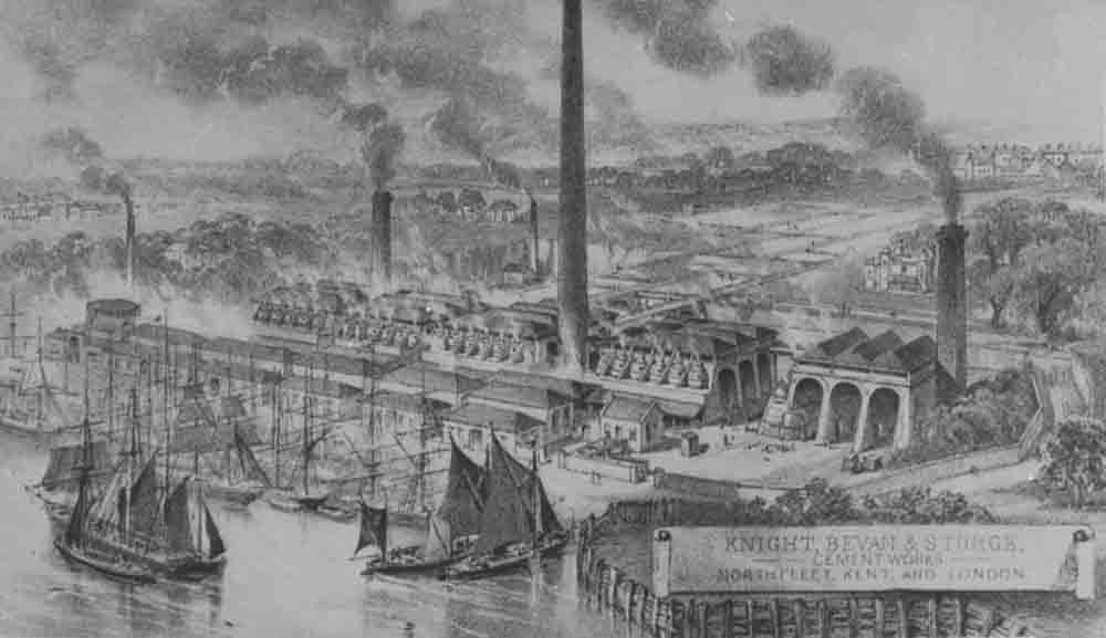 Bevans plant around 1860. The exact date of the image is uncertain, but the plant was shown in this form on the OS map surveyed in 1863-4, and there was little change in the main features during the rest of the century. Some of the kiln blocks were still present at the time of the 1924-8 rebuild.
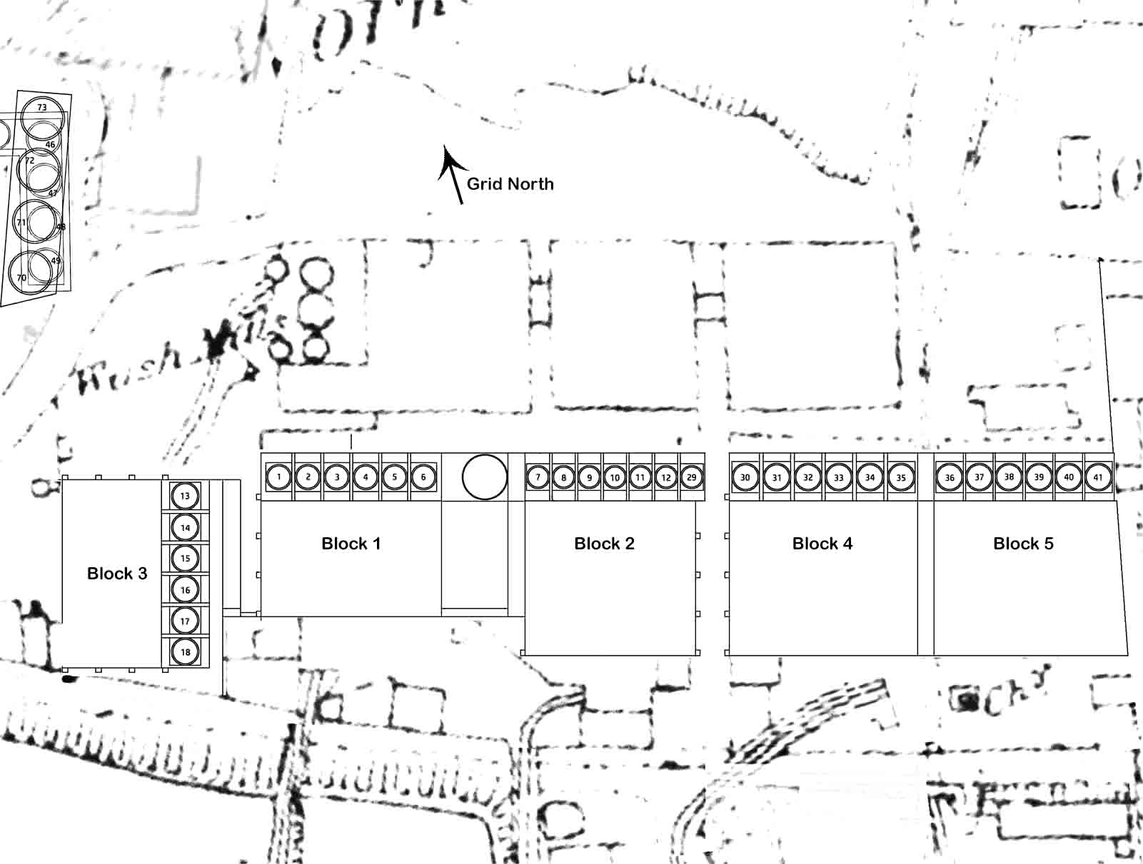 Bevans plant around 1864. The numbering system is my own, attempting to give a sequence of installation. The block numbers are also arbitrary, and will be used in subsequent discussion.
 Rough sketch of a NNE-SSW cross-section through blocks 1 and 2.
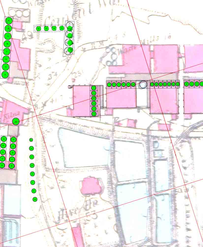 Plan on backdrop of 1864 OS survey (courtesy National Library) showing static kilns.
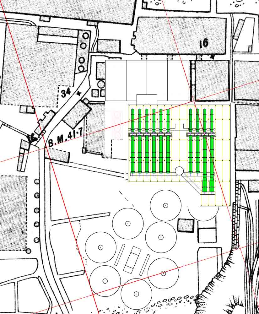 Plan on backdrop of 1907 OS survey (courtesy National Library of Scotland) showing rotary kilns installed up to 1905. The layout of the new finish mill house (north of the kilns) is unknown to me at present. View
 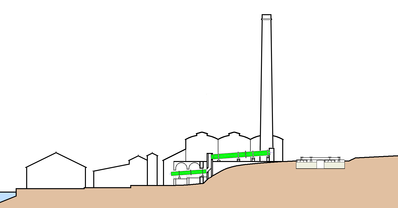 Rough sketch of a NNE-SSW cross-section through the original 80 ft kiln 6.
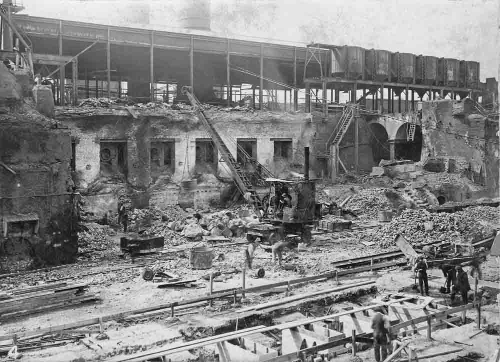 A chaotic scene during the 1925 reconstruction shows many features of the earlier plant. On the extreme right and left are still-standing static kiln blocks. On the right are the old drying flat arches re-used as the firing floor. On the left are the chutes from the kilns to the coolers. The spring of the recently-demolished drying flat arches can still be seen above them. On the right, six of the fine coal hoppers remain. To the rear is the forest of kiln house stanchions with their (mostly) 15 ft spacing that was retained for the later plant, effectively determining the placement of the later kilns. The rear support beds and drives of the new kilns were placed within the building; the third piers were placed just in front of the vertical wall, with the clinker conveyor just in front of them. In the foreground, the bases of the coal mills are being cast.
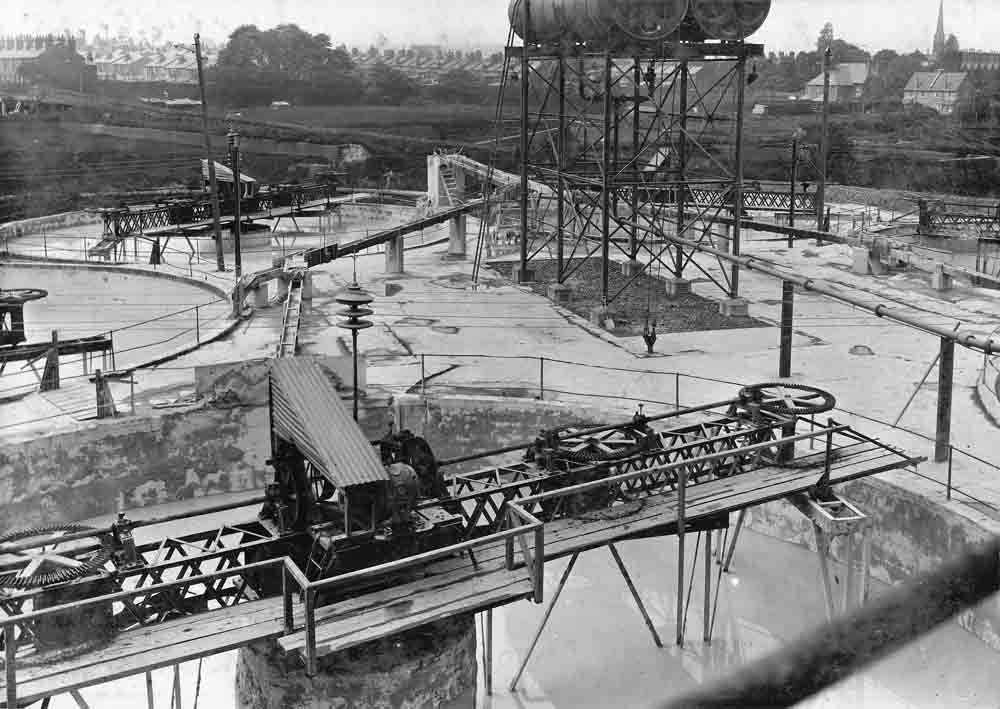 View of the tank farm in 1925. Note the distribution of the slurry in wooden flumes. The mixers are all of identical standard APCM design, with 66 ft internal diameter and a 10 ft centre post. On the right horizon is the spire of Huggens College chapel. On the left horizon are the cement workers' housing of Samaritan Grove and College Street. Behind the mixers can be seen the walls of the old slurry backs.
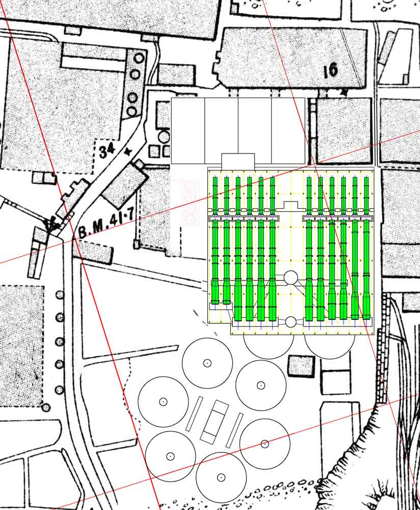 Plan on backdrop of 1907 OS survey (courtesy National Library of Scotland) showing rotary kilns after 1905-6 extensions and kilns added in 1913. View
 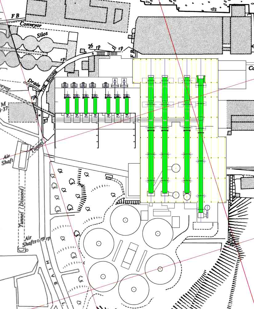 Plan on backdrop of 1952 OS survey (courtesy National Library of Scotland) showing rotary kilns and finish mills as installed 1926-28. View
 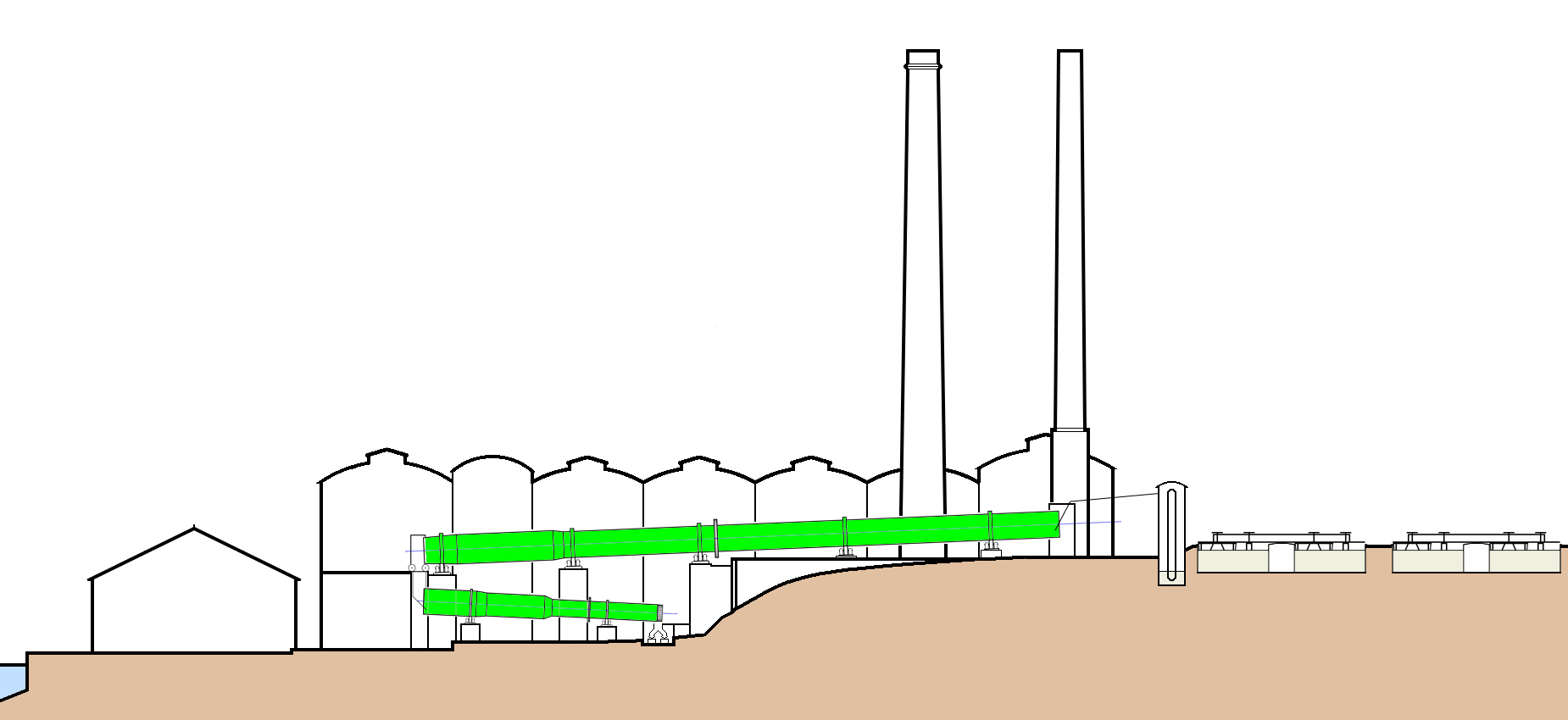 Rough sketch of a NNE-SSW cross-section through kiln 2.
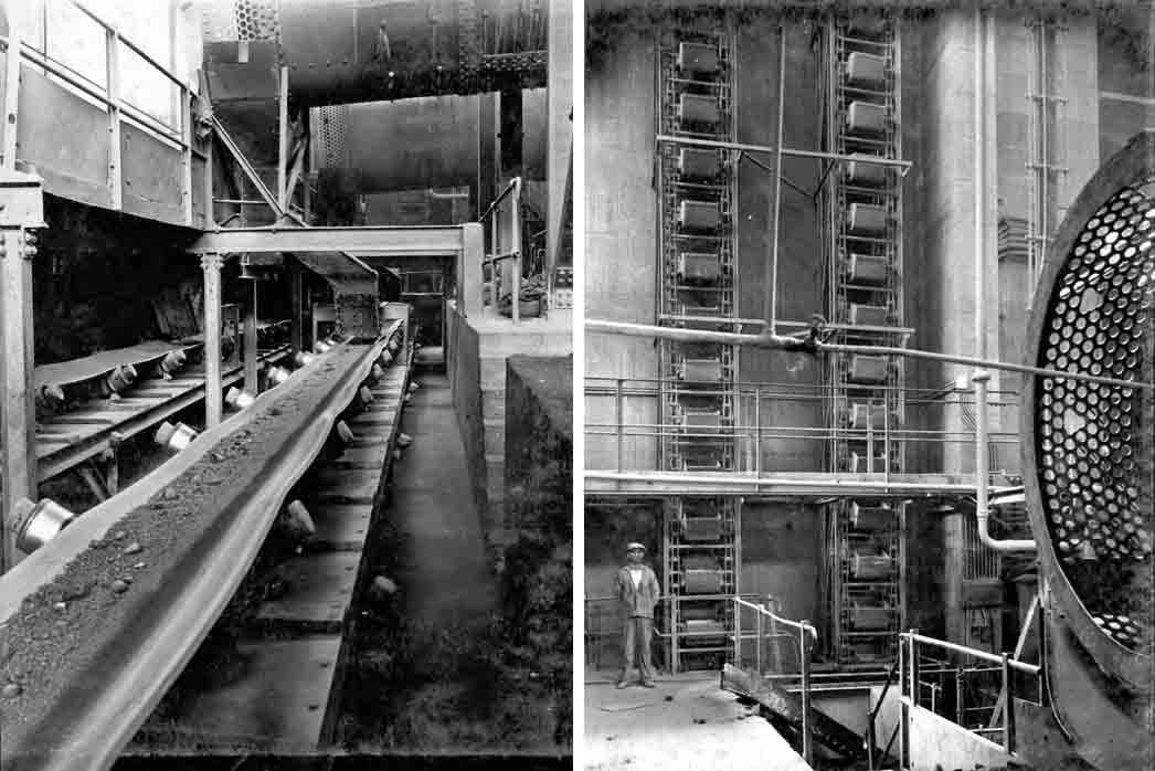 Left: westward view along the two clinker belts under Nos 2 and 1 cooler outlets. Two parallel systems were used so that off-colour clinker could be diverted when necessary. The belts discharge into the elevators faintly visible at the far end. The use of rubber conveyors relied upon a consistently low clinker temperature, and since periodic flushes of hot clinker were inevitable, it was necessary to use occasional water cooling. Right: the clinker elevators, rated at 60 t/hr each.
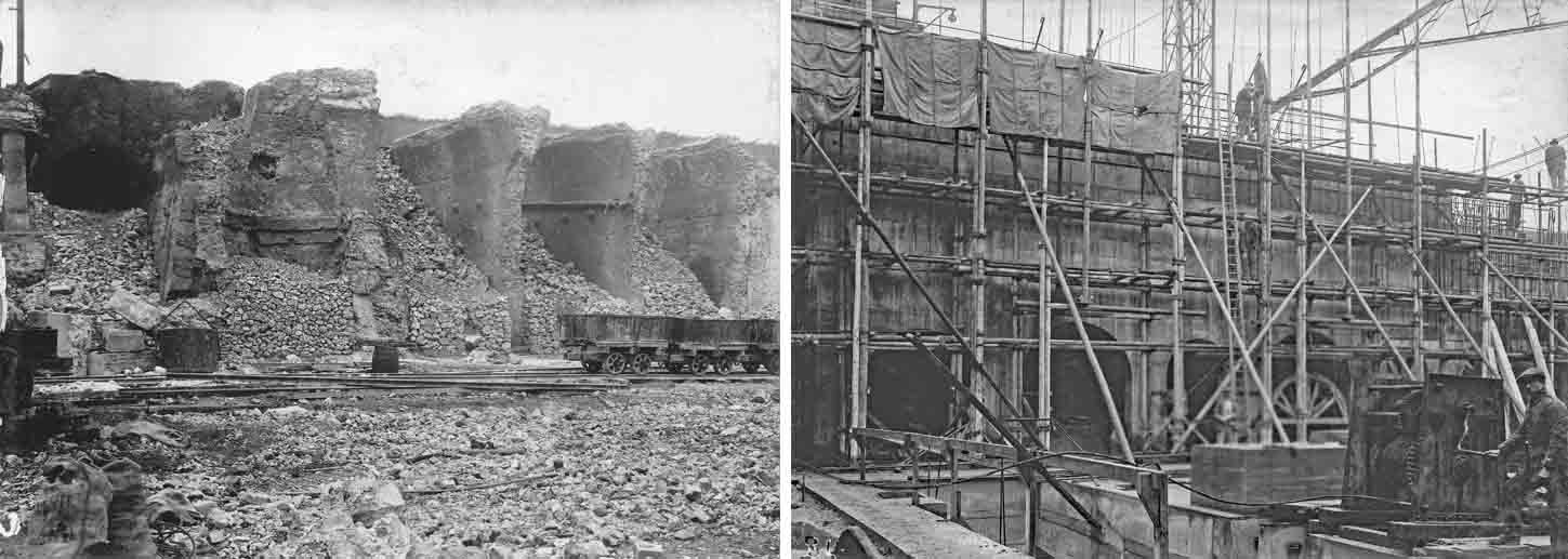 Both views south-westward. Left: Block 3 of static kilns was finally demolished to make room for the new finish mills. Right: the curtain wall on the north of the clinker store. The sloping ground behind the block was concreted over to produce the sloping side of the clinker hoppers which formed the northern part of the clinker store. The finish mills were inserted through tight arches supporting the north wall of the hoppers. It must be supposed that this inconvenient and apparently over-massive design was due to lack of confidence in the reinforced concrete of the time.
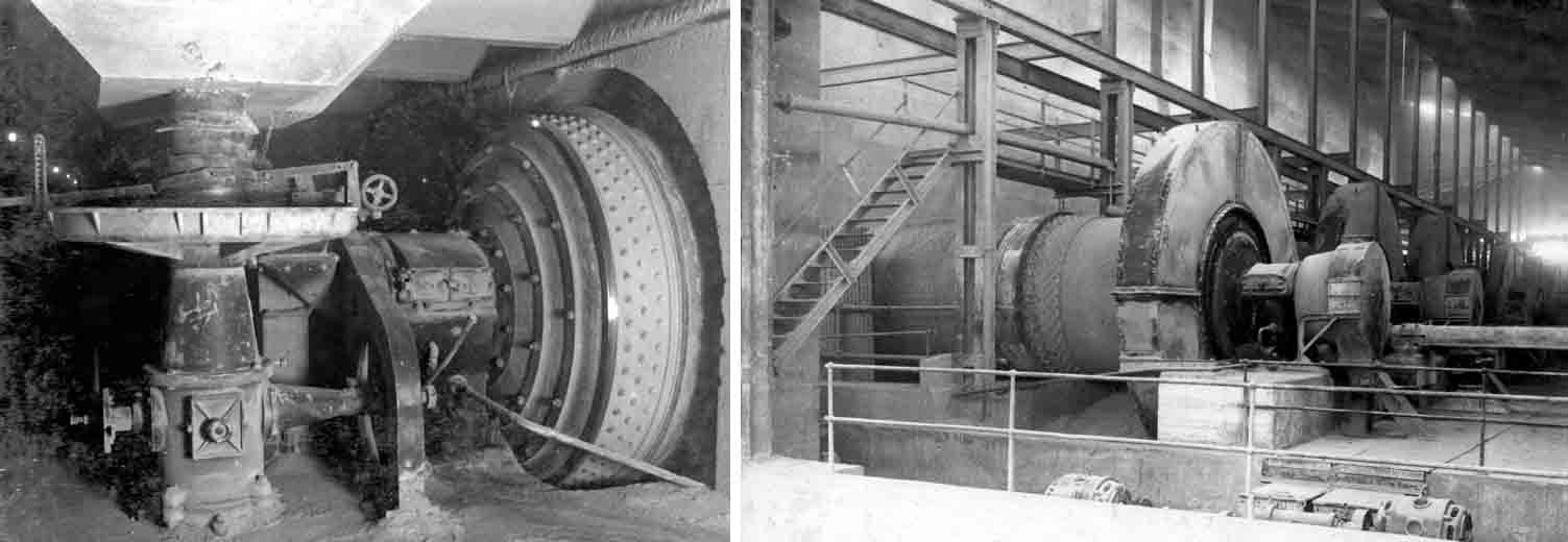 The finish mills (feed end left, outlet end right) were inserted through tight arches supporting the north wall of the hoppers. Because of the small portals in the clinker store wall, the feed area is horribly cramped. Note the shiny metal - it's running in clinker.
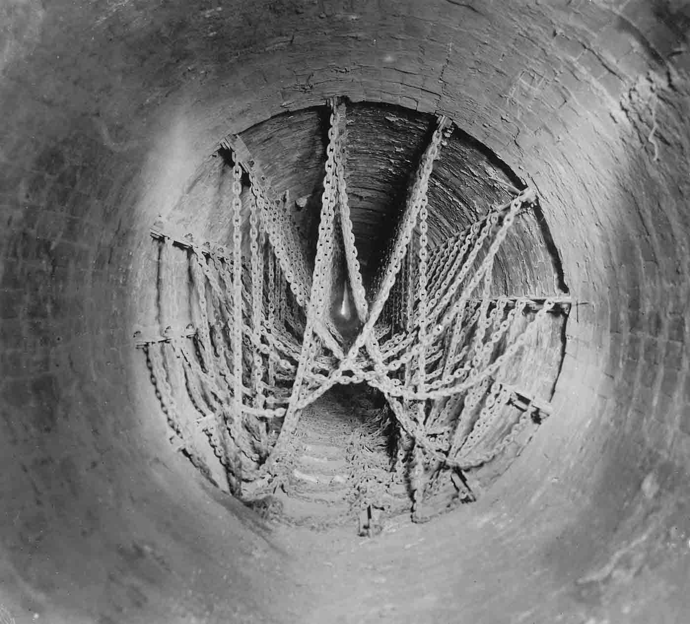 APCM's first chain heat exchangers on Kiln 4. Similar heat exchangers were progressively installed on most other kilns over the following eight years. The system shown is much lighter than later became usual. The chain is small, with with links of ½" bar, 1½" internal length and weighing around 125 g. The whole system probably weighed less than 3 tonnes. Such chains would work only with the very thin slurries assumed by FLS.
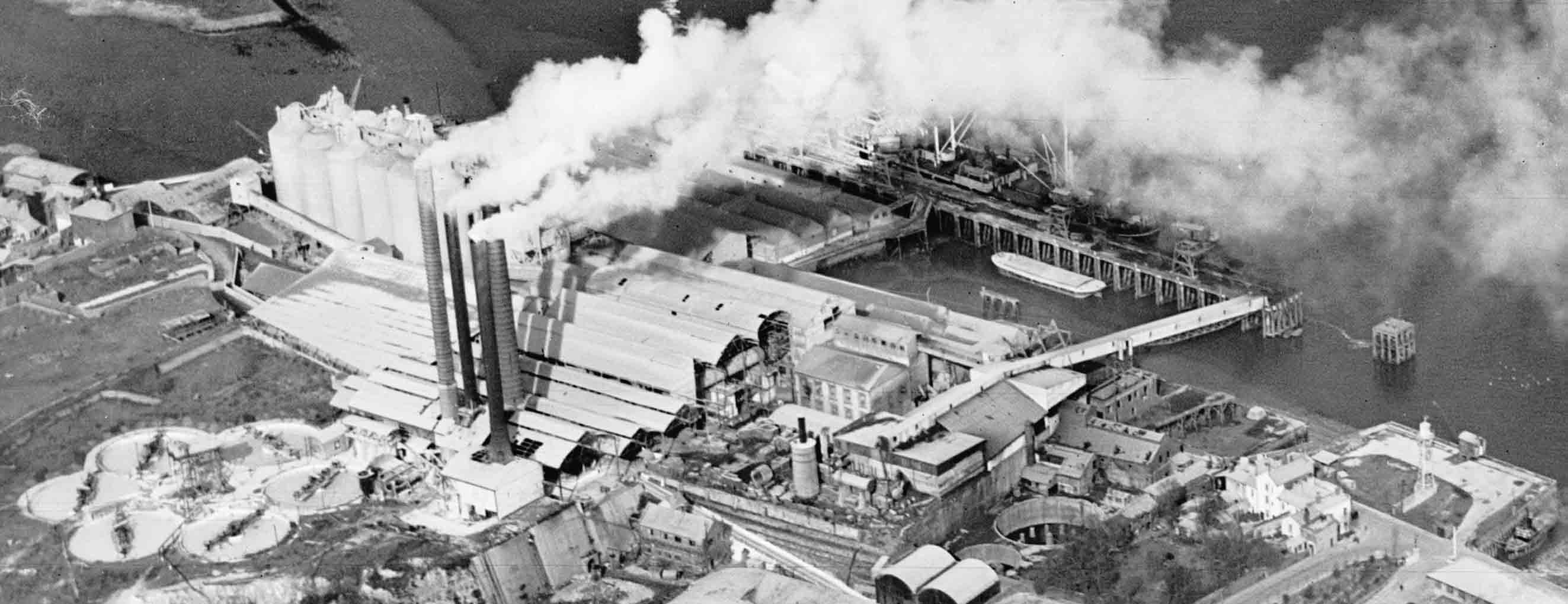 The plant after addition of kiln 4; north-westward view. The kiln area had to be extended further south to accommodate the longer kiln, and an ID fan. The kiln, with its satellite cooler, is visble through the open side of the kiln house.
 Plan on backdrop of 1952-1970 OS surveys (courtesy National Library of Scotland) showing rotary kilns as modified 1958-1960. View
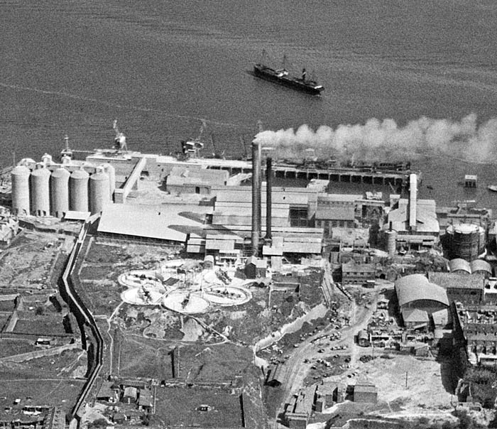 Picture: ©Historic England - NMR Aerofilms Collection. Catalogue number 17642. A high-definition version can be obtained from
 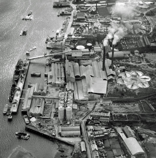 Picture: ©Historic England - NMR Aerofilms Collection. Britain from Above reference number EPW017640.