ROTARY KILN RESEARCH
In accordance with the programme for the reduction of coal used by rotary kilns, further investigations into the working of kilns and coal dryers have been made during the past three months, and drawings for the improvement of various kiln plants have been proceeded with.
CONVENTIONAL TERMS
Certain conventions are used in recording the results of experiments on rotary kilns. They are as follows:-
Unit Output - The unit output of a kiln is the clinker produced in cwt/hour, per 1,000 cubic feet of shell capacity, measured inside the lining. Thus a kiln of 5,000 cubic feet capacity which produced 85 cwt of clinker per hour, would have a unit output of 85/5 equals 17.0.
Standard Coal - All kiln test results are reduced to percentage (on clinker) of standard coal used. This is dry coal of 7,000 calories, or 12,600 B.T.U. per pound. Chimney Draught is expressed in "cents". A cent is equal to 1/100 inch of water gauge.
ENQUIRY No.12 - ROTARY KILN 164' × 7'10½"
This is BPCM's Shoreham plant again, summarising the findings on the kiln, cooler and coal dryer. The findings on the coal mill, delayed by the tedious psd determinations, appears in Enquiry 15 below.
A preliminary account of this enquiry was given in the previous quarterly report; a full description is now supplied.
Kiln Shell
(1) Diameter inside the shell plates = 7'10½"
(2) Overall length = 164'4½"
(3) Capacity of kiln shell inside lining = 6367 cu ft
(4) Slope of kiln = 6%
Slurry lifters of the bracket type are provided, six in circle, the area reckoned on the leading surface being 196 square ft.
The kiln speed is regulated by a variable speed motor.
Cooler Shell
(1) Diameter inside the shell plates = 5'7½"
(2) Overall length 65'7⅜"
(3) Slope of Cooler = 6%
(4) RPM = 2.75
The cooler is lined with 4½" firebrick, at the hot end, for a length of 22'8", then follow cast iron lifters, and finally wrought iron channel lifters.
There is a certain amount of wear and tear on the cooler lining, details which would be to a great extent prevented by a better air supply through it.
Air Passages, Cooler to Kiln. An ample airway is obtained by means of the firebrick shoot used. The limited quantity of air passing up the cooler leads to a high temperature, 1200°F, in the brick shoot, more probably than an iron shoot would stand.
Coal Firing Apparatus. The fine coal hopper holds 30 tons. There are two feed screws at the bottom of the hopper, which are partly shrouded from the coal, and a weight-relieving plate is fixed higher up. It was found during the test that the coal was not being properly supplied to the screws, and it was suggested that the shrouding, and the weight-relieving plate, should he removed.
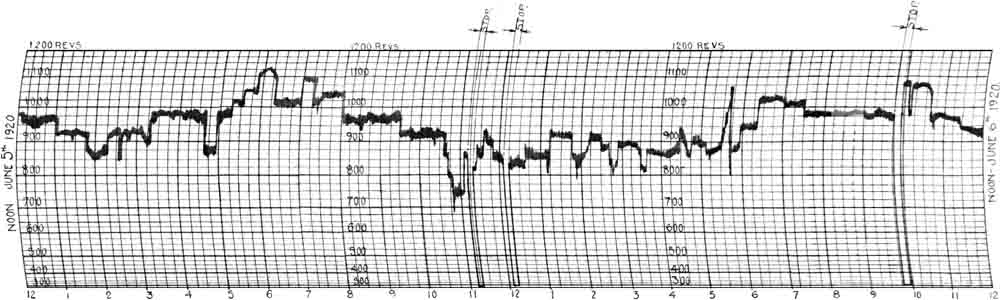
Slurry Feed. There is a rotary spoon feed driven by a rope from the kiln countershaft, hence the rate of feed is proportional to the speed of the kiln. The result is satisfactory, as will be seen from the diagram below showing the kiln speed. The kiln speed, and consequently the slurry feed, is seen to be fairly uniform.
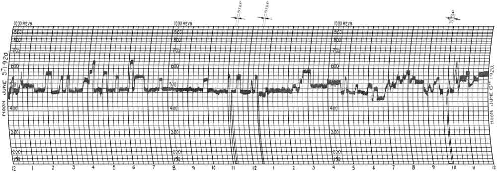
Coal Screw Speed Diagram. This is shown below. There does not appear to be any relation between the coal screw speed, and the rate of slurry feed. It has been previously found, in several instances, that the coal feed screw is speeded up because the coal is not coming freely from the hopper, rather than because a greater coal feed is actually required.
Raw Coal Measurement. This was weighed in the railway waggons over a weighbridge at the works.
Clinker Measurement. This was dropped into trucks from the cooler end, and weighed over a platform weighing machine.
Draught Measurements. Draught recorders were used to give continuous records, as follows:-.
(1) In the kiln hood.
(2) In the flue, opposite the kiln exit end.
(3) In the chimney base.
Temperature Measurements. Continuous records were obtained of the temperature of the kiln exit gases, and of the air entering the kiln by the coal firing pipe. The remaining temperature measurements were observed at frequent intervals.
Speed Measurements. Speed recorders were driven from the kiln gear countershaft, and from the driving shaft of the coal feed screws. The diagrams obtained have already been alluded to.
Kiln Test Sheet. The more important observations are recorded on the kiln test sheet, Sheet No. II.
Only the averages were used from this data sheet, which is too large to show. Available in Excel form on application: enq12_kiln_data.
The chief results are as follows:-
(a) Duration of test: 8 days
(b) Output, cwt per hour: 95.3
(c) Unit output: 15.0
(d) Fine coal, residue on 180#, %: 14.6
(e) Consumption, % standard coal:
(1) as measured: 31.39
(2) Increased to 40% slurry moisture, and deducting 1.61 per cent for water used on clinker rings: 30.15
(3) Add to above figures for coal used on coal dryer: 0.77
Temperature measurements, °F:
(1) Clinker leaving cooler: 293
(2) Clinker leaving kiln: 2365
(3) Clinkering zone, flame temperature: 2759
(4) Clinkering zone, clinker temperature: 2554
(5) Air entering kiln from cooler: 1200
(6) Waste gases at kiln exit end: 737
The temperatures in lines (2), (3) and (4) were taken by an optical pyrometer. The flame temperature is higher than usual. The only unusual feature in the coal firing arrangement is the large diameter (15½") of the coal firing pipe and nozzle, and the consequent low velocity with which the air and coal enter the kiln. This subject is being further investigated.
Draughts: Cents.
(1) In kiln hood: 4
(2) Opposite kiln exit end: 20
(3) In chimney base, above damper: 124
The draught for the kiln is provided by a reinforced-concrete chimney, the top of which is approximately 150 feet above the centre line of the kiln at the exit end. The draught is reduced by the damper to 20 cents in the main flue, opposite the kiln exit end, and it falls to an average of 4 cents in the kiln hood. More draught cannot be used on account of the large leakage area where the kiln enters the hood, hence the air drawn through the cooler is only about 40% of the required quantity.
Air Quantity Measurements
The air entering the hot air chamber per minute is made up as follows (lb/min):-
| (1) Through cooler | 224 |
| (2) By inleakage of cold air | 195 |
| Total | 419 |
The air leaving the hot air chamber per minute is:-
| (3) By clinker shoot to kiln | 188 |
| (4) Supply to coal firing fan | 231 |
| Total | 419 |
Air supply to kiln:
| lb/min | temp °F | |
|---|---|---|
| (5) by coal firing pipe: | ||
| (a) from hot air chamber | 231 | |
| (b) from coal mill | 30 | |
| Total | 261 | 202 |
| (6) by clinker shoot | 188 | 1200 |
| (7) by leaks into kiln hood | 153 | 78 |
| Total | 602 | |
| (8) Average temperature of air entering kiln | 418 | |
The air supply to the kiln, as calculated from the coal burned, and the excess air used, is 580 lb/min, which is in good agreement with the value of 602 lb/min, as deduced from the tilting water gauge measurements.
Details of the calculations are as follows:-
(1) Coal, lb per minute: 58.7
(2) Air, lb per lb of coal necessary for combustion: 8.91
(3) % Excess air used, as deduced from gas analysis. 11.0
Hence calculated air supply = 58.7 × 1.11 × 8.91 = 580 lb/min.
Chemical Measurements
Tests were suggested to, and carried out by the chemical department having for their object the determination of how much of the coal ash was mixed in with the clinker. The test of 8 days was divided into four 48-hour periods. Slurry and clinker samples were taken every hour, and mixed for a 48-hour average sample. The coal ash samples were also taken every hour, and averaged over two periods of 4 days each.
When working out the analysis results, for the sake of comparison, the percentage slurry is calculated to clinker.
| Period | 1 | 2 | 3 | 4 | average |
|---|---|---|---|---|---|
| Slurry analysis (loss-free) | |||||
| Silica | 21.95 | 22.40 | 22.93 | 23.28 | 22.64 |
| Alumina | 6.41 | 6.62 | 6.69 | 7.27 | 6.75 |
| Ferric Oxide | 2.48 | 2.57 | 2.72 | 2.86 | 2.66 |
| S/R | 2.47 | 2.44 | 2.44 | 2.30 | 2.41 |
| Clinker analysis (loss-free) | |||||
| Silica | 22.75 | 22.99 | 23.41 | 23.66 | 23.20 |
| Alumina | 7.60 | 8.30 | 7.86 | 7.53 | 7.82 |
| Ferric Oxide | 2.75 | 2.63 | 2.82 | 2.90 | 2.78 |
| S/R | 2.19 | 2.10 | 2.19 | 2.26 | 2.19 |
| Coal ash analysis | |||||
| Silica | 44.32 | 43.76 | |||
| Alumina | 24.85 | 25.00 | |||
| Ferric Oxide | 7.75 | 8.00 | |||
| S/R | 1.35 | 1.32 | |||
Average results of analysis for the test of 8 days
| coal ash | from slurry | from slurry and all ash | actual clinker | |
|---|---|---|---|---|
| (1) | (2) | (3) | (4) | |
| Silica | 44.04 | 22.64 | 23.94 | 23.20 |
| Alumina | 24.92 | 6.75 | 7.84 | 7.82 |
| Ferric Oxide | 7.88 | 2.66 | 2.97 | 2.78 |
| S/R | 1.34 | 2.41 | 2.21 | 2.19 |
Comparing cols. (3) and (4) it will be seen that by considering the silica, or the iron, about half the coal ash has combined with the clinker, but if the alumina contents are compared, the result is consistent with the absorption of practically the whole of the coal ash.
This is not a complete mass balance, and in particular misses out the dust loss, which would have a significant effect, so it's unsurprising that an inconsistent result is obtained. Rotary kilns at the time had little or no dust arrestment on their exhausts, and there was no method of measuring dust flow rate, so it was therefore expedient to regard dust loss as negligible. Statements regarding dust emission at the time were always specious. In fact, the stacks of the time emitted dust in volcanic quantities.
Clinker Rings. The S/R ratio in the slurry is about 2.41, and owing to the variable feed to the coal mill, the coal is at times coarsely ground. Hence there is a tendency to clinker rings, which is increased by the absence of an enlarged clinkering zone, The output of the kiln is not much reduced by the clinker rings, as the water jet which is used on the average for 5.8 hours per day, is able to remove them. The kiln lining is apparently not damaged by the action of the water.
Surface temperature of kiln shell. Refer to chart below. The shell temperatures are higher than usual, the maximum temperature being over 600°F. The kiln lining is normally only 6" thick in the clinkering zone, and as the kiln had not been stopped for some time, when the temperature observations were made, it is possible that the lining was wearing thin in places. The diagram shows the characteristic fall of surface temperature, over the part of the kiln where the clinker ring deposit is formed.
Heat Balance for Cooler
The figures are as follows:-
| % of total | |
|---|---|
| 1. Heat supplied to air by clinker | 62.2 |
| 2. Heat lost in radiation | 29.4 |
| 3. Heat lost in outgoing clinker | 8.4 |
| 4. Cooler efficiency | 62.2% |
Heat Balance for Kiln
| standard coal | |
|---|---|
| % on clinker | |
| (1) Heat required to decompose CaCO3 | 7.15 |
| (2) Heat required to raise CO2 from raw material to exit gas temperature | 0.63 |
| (3) Heat required to evaporate and superheat moisture in slurry | 10.56 |
| (4) Heat required to raise products of combustion from coal to temperature of exit gases | 5.38 |
| (5) Heat required to raise excess air to temperature of exit gases | 0.41 |
| (6) Radiation loss from kiln | 3.30 |
| (7) Radiation loss from cooler | 1.32 |
| (8) Hot clinker loss at cooler delivery end | 0.38 |
| (9) Loss due to water used on clinker rings | 1.32 |
| (10) Calculated consumption, standard coal: | 30.45 |
| (11) Add loss of heat unaccounted for | 0.94 |
| (12) Kiln consumption, as measured, standard coal | 31.39 |
| (13) Useful effect of coal, including the excess air loss, % | 81.5 |
The measured standard coal consumption of 31.39% is equivalent to 8.83 MJ/kg (nett) in modern terms. Another 0.22 MJ/kg was used in the coal dryer.
General Conclusions Drawn from Test
(1) With a slurry moisture of 39.2%. it should be quite practicable to run the kiln continuously with a unit output of 17.5, and a standard coal consumption of 26.0%, providing the clinker rings can be eliminated. In this connection the use of finer ground coal is suggested.
(2) Sufficient air for the supply of the kiln should be taken up through the cooler, either by the use of forced draught or by an enlarged clinker shoot.
(3) A few more slurry lifters could be installed with advantage.
(4) A temperature recorder is required for the kiln exit gases.
(5) Some method of weighing the clinker, as it leaves the kiln is desirable.
ENQUIRY No.12 (CONTINUED): TESTS ON COAL DRYER
The dryer comprises an inclined cylindrical steel shell, 4'9" in diameter, and 45'0" long, which revolves in a brickwork housing. There is an inner tube, arranged centrally, 2'6" in diameter, by 32'0" long, which is blanked off at each end. Heat is supplied by a coal fired furnace. The hot gases pass first round the outside of the dryer shell, and then enter the inner tube, at the lower end, by means of four short connecting pipes, each of 16" dia. The gases leave the inner tube, at the upper end, by four similar pipes and pass into a brickwork pocket, finally escaping by an iron chimney, marked A.
It was found in practice that the chimney did not provide sufficient draught for the furnace with the complicated system of airways described, hence an additional smaller chimney, marked B, was provided for the outer chamber, at the end opposite to the furnace which allows the gases to pass to atmosphere, after passing the outside of the shell only.
A fan draws off the steam from the coal, and the air due to inleakage, and passes it to the large chimney. The arrangement of the coal dryer furnace is shown at Fig.2.
Test No.1
The raw coal way weighed in the railway wagons on a weighbridge at the works; the coal required by the furnace was weighed out previous to the test, in bags holding one cwt.
Observations wore taken at regular intervals daily of the moisture in the raw coal, also of the moisture and temperature of the coal leaving the dryer.
Furnace, air supply &c. The furnace used 1.30 lb of dry coal per minute, the calorific value being 14450 BTU (/ lb). The air required to burn one pound of coal is 10.17 lb. The air actually entering under the furnace bars, as measured by an anemometer, was 15.5 lb per lb coal corresponding to 52.5% excess air.
Total heat in gases entering the coal dryer outer chamber. Observations were made at the back of the arch, behind the furnace (at point K, see drawing), on the composition and temperature of the gases passing that point. The average temperature, as taken on a Thread Recorder throughout the test, was 1090°F>
A series of observations were made with an Orsat gas-analysis apparatus, using a water jacketed collecting pipe, the average result being O2 = 13.7, CO2 = 6.6. It will be seen that the excess air present, as estimated from the O2 was 184%, and as estimated from the CO2 173%. Taking the average figure, it is calculated from the various quantities and specific heats, that the total heat in the gases per pound of coal, passing point K, is 7517 BTU. The calorific value per pound of coal is 14460 BTU, hence 52% of the total heat of the coal is present as sensible heat in the gases. A somewhat similar result was found for the gases leaving the furnace tube of a dryer fired with powdered coal (Enquiry No.6). It is difficult to see in this instance what becomes of the balance of 48% of the total heat. A portion no doubt passes through the firebrick arch, and is radiated to the dryer shell; a further portion would be radiated to, and pass out through the chamber walls.
Conditions at entrance to small chimney of dryer. The measurements made at this point are as follows:-
(1) Average temperature of gases: 319° F
(2) CO2: 3.1%
(3) CO2: 17.6%
(4) Average excess air: 500%.
Using the above figures, the quantity of gases entering the chimney, including 3.4 lb of steam from the coal, is calculated to be 88.8 lb/min. The average of the air gaugings by the tilting water gauge gave the quantity as 89.0 lb/min, hence it is probable that all the products of combustion from the furnace pass up this chimney.
Test Results
(1) Duration of Test: 192.0 hr
(2) Actual running time of dryer: 152.3 hr
(3) Moisture in coal before drying: 7.1%
(4) Moisture in coal after drying: 3.6%
(5) Moisture in coal after after grinding: 2.4%
(6) Moisture evaporated: 2.6 lb/min
(7) Coal entering dryer: 1.798 dry tons
(8) Size after drying: residue on 1": 1.1%
(9) Residue on ½": 12.3%
(10) Residue on ¼": 22.4%
Temperatures:
(11) gases entering outer chamber of dryer at point K: 1090°F
(12) gases entering small chimney of dryer: 319°F
(13) air and steam leaving dryer interior: 103°F
(14) coal entering dryer: 64°F
(15) coal leaving dryer: 160°F
Air quantities:
(16) Entering furnace ash pit: 21.4 lb/min
(17) Entering small chimney of dryer: 89.0 lb/min
(18) Speed of dryer: 3.3 rpm
(19) Furnace coal used: 82.5 dry lb/hr
(20) Calorific value of coal (dry): 14450 BTU/lb
(21) Moisture in coal: 8.6%
Heat Balance for Test No.l
| BTU/min | |
|---|---|
| (1) Heat required to decompose CaCO3 | 7.15 |
| (1) Heat supplied: 1.38 × 14450 | 19900 |
| Heat used: | |
| (2) Heat expended in evaporating moisture | 2855 |
| (3) do. in raising temperature of coal | 2125 |
| (4) do. in raising temperature of contained moisture | 244 |
| (5) Heat lost in gases passing up small chimney | 5080 |
| (6) Heat lost in steam and air leaving dryer interior | 861 |
| (7) Radiation, loss due to stoppages, and loss unaccounted for | 8735 |
| Total | 19,900 |
| (8) Moisture evaporated per pound of standard coal, lb | 1.64 |
It is somewhat difficult to account for the large loss in line (7), it would be partly due to stoppages, as the dryer only ran 79% of the total time available, also the furnace and part of the interior is heated up to a high temperature, whilst there is a relatively small evaporation. Hence the radiation and stand by losses would form a large percentage of the total.
Test No.2
In the previous test there was no circulation of hot air through the dryer interior, as the hot gases all left the outer chamber by the small chimney marked B. During the second test a small fan was used to supply hot air from the cooler to the interior of the dryer shell. A regular feed was provided by weighing in barrow loads of 2 cwt of coal, every three minutes.
On this test the evaporation per pound of coal (taking into account the heat received from the hot air chamber) was increased from 1.64 to 2.30 lb and the loss unaccounted for was reduced from 44% to 29.6%. The latter test was a short time test, made with a regular feed, and under constant supervision.
A design is being prepared for the improvement of the dryer. It is proposed to use hot air from the cooler, which will be passed first round the outside of the dryer shell, next through the interior, and finally blown into the kiln by the coal firing fan. This method admits of a relatively large circulation of hot air through the dryer interior, the coal dust carried out by the air, being blown into the kiln.
ENQUIRY No.14 - ROTARY KILN 130' × 7'4⅝"
This relates to APCM's Vectis plant. The plant was converted to mainly rotary production in 1913, with a small Newells kiln of somewhat eccentric design. A number of inefficiencies of the plant were addressed and modifications were subsequently made.
This enquiry relates to a kiln 130'4" long, working on the wet process. The diameter inside the shell plates is 7'10¾" for a length of 47'6" at the hot end, the diameter of the remaining portion being 7'4⅝".
The kiln has a short cooler, large in diameter, which admits of a brick clinker shoot being applied under favourable conditions. The kiln coal feed is provided with an overflow arrangement.
The silica ratio in the raw materials has a low value, about 2.14, and clinker rings are of frequent occurrence.
The coal is ground by a pendulum mill.
The coal dryer is of the Ruggles Coles type, a separate furnace being provided.
The kiln was tested for eight days with the following result:-
1. Output, cwt per hour: 57.6
2. Unit output: 13.4
3. Standard coal, %: 34.4
The rather high coal consumption, and low output, was not due to any defect in the mechanical appliances but to reduced feeds and stoppages caused by clinker rings. A full report of the above test will shortly be issued.
PRELIMINARY REPORT BY THE NATIONAL PHYSICAL LABORATORY ON HEAT LOSSES FROM THE SHELLS OF ROTARY KILNS
A report of 27 pages, with two mounted photographs, and nine blue prints, has been received from the National Physical Laboratory.
The formula so far used by the Research Staff to calculate the heat lost by radiation and convection, from the surface of rotary kilns and coolers, is based on some small scale experiments made at Finsbury Technical College. A wrought iron cylinder, a few inches in length, was heated internally by an electric coil, sufficient current being supplied to maintain the surface temperature steady, and at any desired value. Under these conditions the heat supplied by the electric current (which is easily measured) is equal to the heat lost by radiation and convection, at the surface temperature considered. The temperature was observed by the same type of apparatus, as is used to take the surface temperature of kiln shells.
The above experiment gave the total heat loss, per square foot of cylinder surface per hour, at each surface temperature considered. Applied to rotary kilns it is incomplete for the following reasons:-
(1) The small diameter of the experimental cylinder, the heat lost by convection per square foot being considerably greater than it would be for cylinders approaching the size of rotary kilns.
(2) The additional heat loss, if any, due to the rotation of the kiln was not known.
(3) The experiments were made in the still air of a 1aboratory; the additional heat loss due to exposure to wind and weather was uncertain.
It was arranged that the work of the NPL should be generally directed towards clearing up the points listed above.
Work done by NPL. After an exhaustive review of all known experiments on the subject the conclusion was arrived at that a cylinder of 9 inches diameter would be large enough to truly represent, per square foot of surface, the heat lost from a rotary kiln shell at the same surface temperature. A cylinder of this size was heated by electricity in the manner previously described. The total heat loss in a still atmosphere at various surface temperatures is given on page 15 of the report, which is here reproduced.
Heat Lost from Surface of Experimental Cylinder (Calorie per cm2 per second)
| temp excess,°C | total loss | radiation loss | convection loss |
|---|---|---|---|
| 100 | 0.0034 | 0.020 | 0.014 |
| 150 | 0.062 | 0.039 | 0.023 |
| 200 | 0.101 | 0.066 | 0.035 |
| 250 | 0.147 | 0.100 | 0.048 |
| 300 | 0.208 | 0.145 | 0.063 |
| 350 | 0.282 | 0.204 | 0.078 |
| 400 | 0.375 | 0.280 | 0.095 |
| 450 | 0.489 | 0.376 | 0.113 |
| 500 | 0.616 | 0.485 | 0.131 |
The NPL probably specified which calorie they were using, but if they did, it's not mentioned here. The conversion factors given imply that they are using the Thermochemical Calorie (4.1840 J) rather than the IST Calorie (4.1868 J) and the 60°F BTU (1054.54 J) rather than the IST BTU (1055.06 J). The "lb °C heat unit" is 1.8 BTU (of whatever unspecified definition) and its inclusion suggests that some people were using even more eccentric units of energy. The radiation shown slightly exceeds that predicted by the Stefan-Bolzmann law for emissivity = 1. The Steffan's law constant was generally only known empirically at the time, and was routinely over-estimated. The fact that it is a Fundamental Constant was known at the time, but only to the few who were familiar with quantum physics.
NOTE:
(a) To convert calories per cm2 per second into BTU per ft2 per hour, multiply by 13270.
(b) To convert calories per cm2 per second into lb °C Heat Units per ft2 per hour, multiply by 7372.
The results are generally speaking about 1/5th less than that given by the formula previously used by the research staff. In addition, the range of the experiments has been extended from 720° to 930°F.
After determining the total heat loss by measuring the input of electrical energy, the NPL attempted to measure directly, and separately, the heat leaving the surface of the cylinder by radiation and by convection. Some very useful work was done in this connection.
Ultimately the radiation as measured by a radiation pyrometer was taken to be correct, and the convection loss at various temperatures was obtained by deducting the radiation loss, so found, from the total loss as measured by the input of electrical energy. The radiation and convection losses as determined are given in the table already quoted.
Effect of Rotation. It is shown by calculation, based on the principle of similarity, that to be representative of the heat loss from a rotary kiln, of 9' diameter, due to its rotation, the 9" diameter cylinder would have to rotate at 144 rpm. The cylinder was rotated at speeds greater than this, and the effect of rotation was found to be negligible.
Effect of exposure to wind. A formula due to Professor Osborne Reynolds is quoted, and some small scale experiments by Hughes are discussed.
It is then deduced by the principle of similarity, that for low wind velocities, such as 12 miles per hour, the heat loss from rotary kiln shells would be directly proportional to the wind velocity, and to the shell temperature. The investigation is not yet carried to the point of determining the actual additional heat loss due to any known wind velocity.
Measurements of Shell Temperature. The shell temperature was measured by the NPL by embedding a mercury thermometer in a longitudinal groove planed in the cylinder. Also by drilling holes in the shell, which were filled by easily fusible metal, to form thermometer pockets. It is suggested that this method of measuring temperature should be more thoroughly compared with the thermal junction contact method used by the research staff, as the latter method is alone practicable for rotary kilns.
Further Work. The experiments to determine experimentally the effect of wind of various velocities on the convection loss, which was one of the principal objects of the original enquiry, yet remain to be done. The work so far accomplished however has prepared the ground, to a considerable extent, for these concluding experiments.
GRINDING PLANT RESEARCH
The estimated cost of the 30" × 72" experimental mill alluded to in the last report is as follows:-
| £ | |
|---|---|
| (1) Iron parts for mill | 375 |
| (2) Ball bearings for mill | 60 |
| (3) Grinding media, charge 30 cwt, allow for four different charges | 240 |
| (4) 15 HP variable speed DC motor with switchboard and instruments complete | 150 |
| (5) Erection of mill and motor, including concrete foundations wiring and sundries | 150 |
| Total | 975 |
For wet grinding experiments probably a small mixer will also be required.
The Council decided to order the mill complete, and to make enquiries as to whether the driving motor, grinding media, &c. could be obtained on loan from Members of the Association.
Further tests on 18" × 18" experimental mill
Since the date of the last quarterly report several tests have been made, using holpebs as grinding media, and one test has been made using 2" dia. steel balls. It will be remembered that a series of tests on the 18" mill are now being made; standard sand screened through 20#, and retained on 30#, is used in all cases, as the material to be operated upon. So far all tests have been made with lifter bars secured to the lining plates.
Summary of results to date
The earlier tests on the 18" dia. experimental mill were made at one speed, but the quantity of sand in the mill was varied from 115 to 35% of the volume of the interstices.
It will be seen from the annexed table that generally speaking the percentage of sand may be anything from 40 to 90% without much loss of efficiency.
This table is too large for web display but is available as an Excel file: 18_inch_mill_data.
Subsequent tests were made at various speeds, at the suggestion of Mr Blyth. The effect of speed variation is perhaps more marked, than a variation of the quantity of sand in the mill. An inspection of the results shows that the best speed, using lifter-bars on the lining plates, is given approximately by the formula N = 175 / √d.
The low efficiency obtained with 2" dia. steel balls will be noted. The latter result suggests that it would be desirable to try ¾" dia., or even ½" dia. balls, in the 18" mill.
ENQUIRY No.15: Test of Tube Mill with two Chambers for Coal Grinding
This, once again, is Shoreham - a BPCM plant. Kiln 3 was supplied (1911) by Krupp, who also supplied an early combination tube mill for coal grinding, fed with dried coal from a rotary dryer.
The coal grinding plant consists of a single tube mill, divided into two chambers by a diaphragm plate. It was .intended to test the coal mill for days concurrently with the kiln, refer enquiry No.12 but it was subsequently found that the feed to the mill was not altogether regular, partly owing to the special arrangements which had to be made for weighing in the coal during the kiln test.
The coal mill was therefore tested after the kiln, and under conditions which ensured a regular feed. Three tests were made as follows:-
Test No.1. Made at normal output. The apertures in the division plate between the chambers were about 80% blocked with small pieces of iron.
Test No.2. Made at 25% below normal output, with the division plate blocked as before.
Test No.3. Made at normal output, but with the apertures in the division plate punched out clear.
The report is divided into three parts as under:-
Part I. Data relating to mill.
Part II. Detail of tests.
Part III. Calculations of new surface produced.
PART I
Data relating to preliminary chamber:
(1) Dimensions inside lining plates: diameter 3'0", length 10'0¾".
(2) Description of lining: cast iron blocks, 9" × 4½" × l⅛" set in diamond cement.
(3) Grinding media: steel balls
Weight of charge during tests: 85.46 cwt
Average weight of balls: 1.0 lb
Average diameter of balls: 1.90"
(4) Exit openings from chamber:
The division plate has curved slots, from 3" to 4½" long, extending from a radius of 5", up to the mill circumference. Width of slots 11/32" at inlet, ½" at outlet.
Slot area = 172 square inches.
Data relating to Finishing Chamber:
(5) Dimensions inside lining plates: diameter 2'11⅜", length 16'1⅜"
(6) Description of Lining: as (2) above.
(7) Grinding_Media: Cylpebs.
Weight of charge during test = 108.53 cwt
Average weight of cylpebs = 3.0 oz
The cylpebs have been in use for a considerable time, and the ends are well rounded.
(8) Exit openings from Chamber. The discharge is central, through the mill journal. The diaphragm plate is 17½" dia. and provided with curved slots from a radius of 2¼", up to the circumference. The slots are parallel, 5/16" to ⅜" wide. Slot area = 85 sq.in. The apertures were practically clear throughout all tests.
General Data
(9) Mill bearings:
(a) Feed journal 11 15/16" dia, length 15"
(b) Outlet journal 24 7/16" dia. length l1⅝"
(10) Driving Arrangement. The mill is driven by an electric motor, receiving direct current at 112 V. There is a belt drive from the motor to the mill countershaft, also a friction clutch on the countershaft.
(a) Resistance of motor armature circuit = 0.026 Ω
(b) Resistance of motor field current = 20.143 Ω
(c) Average shunt current = 5.65 amperes.
PART II
Details of Test
Raw Coal - Quantity etc. The raw coal was tipped to the coal dryer in barrow loads of 2 cwt. An equal interval of time was allowed between each barrow load, and as the coal dryer delivers directly to the mill inlet, a fairly regular feed was ensured in this manner. A sample of coal was taken from each barrow for moisture determination in order to enable the equivalent feed in dry coal to be calculated.
Regular feed conditions were set up for one hour before each test was started, the actual test then being of 5 hours duration.
Sieve tests. Sieve tests were made on the fine coal at half-hourly intervals.
Measurement of BHP supplied. Measurement of the voltage and current supplied to the motor, were taken every 10 minutes throughout each test, uniform readings being obtained. At the end of the tests the power supply to the motor was measured, with the friction clutch on the mill countershaft disconnected. The BHP supplied to the mill is calculated from the difference of these readings, a suitable correction being made for the motor losses in each case.
Readings were also taken of the power supplied to the motor with the belt removed; the power absorbed by the belt, and the part of the mill countershaft carrying the belt pulley being thus obtained.
Axial Sieve Tests. At the conclusion of tests Nos.1 and 3, the mill was suddenly stopped, when on normal feed, and samples of grit coa1 were taken in five equidistant positions longitudinally in the preliminary chamber, and similarly in the finishing chamber. The sieve test results are plotted in diagram form below. The base of each diagram is divided to represent BHP per ton ground per hour, and the vertical ordinates represent the sieve residues corresponding to the HP expended.
The subdivision of the BHP between the two chambers is calculated from the known weights of the charges and grit coal present in each case. From these curves the BHP per ton ground per hour, referred to 20% on 180#, is obtained. It will be seen to be 35.3 for test .No.1, and 38.2 for test No.3.
TEST RESULTS
(Refer to notes below)
| Test 1 | Test 2 | Test 3 | |
|---|---|---|---|
| Date of Test | 15/6/1920 | 16/6/1920 | 18/6/1920 |
| Duration of Test, hours | 5 | 5 | 5 |
| Moistures, %: | |||
| (3) Moisture in coal entering PM | 3.8 | 4.9 | 5.2 |
| (4) Moisture in coal leaving FM | 2.8 | 2.2 | 4.2 |
| (5) Rate of feed, dry tph | 1.85 | 1.38 | 1.81 |
| (6) Fine coal, residue on 76# | 0.6 | 0.3 | 0.6 |
| Fine coal, residue on 100# | 2.4 | 1.3 | 3.0 |
| Fine coal, residue on 180# | 18.6 | 11.6 | 20.1 |
| Speed: | |||
| (7) Mill average rpm | 34.2 | 34.4 | 34.3 |
| (8) constant in speed formula | 205.0 | 206.0 | 205.5 |
| Power BHP: | |||
| (9) supplied by motor (belt and half countershaft not included) | 70.0 | 70.7 | 69.1 |
| (10) Extra power taken by belt, short countershaft, and half friction clutch | 5.51 | 5.51 | 5.51 |
| (11) Estimated for PC | 29.1 | 29.4 | 28.7 |
| (12) Estimated for FC | 40.9 | 41.3 | 40.4 |
| (13) per ton ground per hour | 37.8 | 51.2 | 38.1 |
| (14) referred to 20% on 180# | 35.3 | - | 38.2 |
| (15) Value of constant in BHP formula: | |||
| (a) Grit coal included in weight of charge | 897 | 894 | 912 |
| (b) Grit coal not included | - | 843 | - |
| Coal in Voids | |||
| (16) Grit coal amongst grinding media: | |||
| (a) PC = 7.6 cwt | |||
| (b) FC = 5.04 cwt | |||
| (17) Calculated ratio, grit coal to voids (a) PC | - | 118% | - |
| (b) FC | - | 83% | - |
| New Surface | |||
| (18) New Surface per BHP per hour, PC | 91450 | 80000 | 84000 |
| (19) New Surface per BHP per hour, FC | 72000 | 67500 | 65200 |
| (18) New Surface per BHP per hour, mill | 80000 | 72600 | 73100 |
Notes on Table of Test Results:
PC = preliminary chamber
FC = finishing chamber
Speed formula: N = constant / √d
where N = speed rpm
d = diameter inside lining, in inches
BHP formula: BHP = W×X×N / constant
where W = weight of charge in cwt
X = distance from centre of mill to centre of gravity of charge in inches
N = speed rpm
Speed Measurements. In the various calculations of power required to produce new surface etc. the extra power in line (10) above is not included.
PART III
Calculation of New Surface produced:
The method of calculating the new surface produced has been previously described, and it was shown that surface of cubes in grade = 0.825 × W / s
where W = weight of coal in grade
S = average particle width in grade.
Using the sieve gradings, it was calculated in the usual way that taking 100 lb of coal, we have for Test No.1 surface in ft2:
(1) entering preliminary chamber 6086
(2) leaving preliminary chamber 70225
(3) leaving finishing chamber 141085.
(4) hence new surface produced by the preliminary chamber per 100 lb coal = 70225 - 6086 = 64139 sq ft.
(5) new surface produced by the finishing chamber per 100 lb coal = 141085 - 70225 = 70860 sq ft.
Now the mill ground 1.851 tons of coal per hour with an expenditure of 29.1 BHP in the preliminary chamber, and 40.9 BHP in the finishing chamber.
(6) Hence new surface produced by preliminary chamber per BHP hour is:
1.851 × 22.40 × 64139 / 29.1 = 91450 sq ft.
(7) New surface produced by finishing chamber per BHP hour is:
1.651 × 22.40 × 70860 / 40.9 = 72000 sq ft.
The new surface produced per BHP per hour, for Tests Nos.2 and 3 are worked out in a similar manner, and the results are given in the table above.
The results are worked out separately for the preliminary chamber and the finishing chamber, but a sample of the coal passing through the division plate could not of course be obtained during the test. At the end of the test therefore the mill was suddenly stopped when on normal feed, and samples of coal were taken from the mill interior, and immediately adjacent to the central diaphragm plate, one on each side. The surface of the coal leaving the preliminary chamber was worked out from the average of these two samples.
Comparison of Tests 1, 2 and 3
The conditions under which the three tests were made are given above. Returning to the table of test results above and comparing tests 1 and 3, it will be seen from line (14) that the BHP per ton ground per hour, referred to 20% on 180#, was 35.3 and 38.2 in the two cases. This result is generally confirmed by the new surface produced per BHP per hour - see line (20).
For the test 2 at the reduced output, line (20) shows that the new surface produced, per BHP per hour, was 72600 sq ft, hence compared with test 2, which was made under the same conditions as regards the division plate, the mill was not quite so efficient when the finer grinding was being done.
General conclusion. The three tests are consistent as regards the new surface produced per BHP per hour, the values being 80000 sq ft, 72000 sq ft and 73100 sq ft respectively.
ENQUIRY No.16 Test of Pendulum Mills
This, once again, is APCM's Vectis plant. The two Griffin mills used to grind coal were examined at the same time as the kiln test, but the report was delayed by the tedious psd analyses, which were still incomplete at this stage.
These are the mills referred to in Enquiry No. 14. Two are in use, one used for grinding, and one as a standby. The mills are alternately in use, The plant was tested for eight days with the kiln. The average performance for each mill was 1.77 tons dry coal per hour, to a residue of 28.4% on 180#, the BHP for the mill only, with belt and driving pulley being:-
Mill No.1 31.8
Mill No.2 21.8
Both mills were recently fitted with new grinding rings. An average sample of fine coal has been elutriated, and the new surface is being worked out.
RAW MATERIALS RESEARCH
The general programme for this research was given in the report for the 6 months ending March 1920. Since that date work has chiefly been towards the provision of a suitable experimental kiln. The use of a full sized rotary kiln was considered for clinkering the various raw materials and mixtures referred to in the programme, but the idea was ultimately abandoned, on account of the large quantity of unusable clinker which would probably be made during the various tests. A rotary kiln of laboratory size, say 3 to 4 ft. long, would make sufficient clinker, but the difficulty of measuring in such a small kiln, the heat required for clinkering, was thought to be a serious drawback.
Ultimately a kiln 3 ft dia. inside the shell plates, (or 2 ft dia. inside the lining) and 30 ft long, was decided upon. The diameter is sufficient to allow repairs to the lining to be effected without dismembering the shell, and, the kiln is large enough to admit of a measurement of the heat used with fair accuracy.
It is estimated that the clinker output per hour should be 1 to 1¼ cwt.
A preliminary design has been prepared for such a kiln, equipped alternately for oil, and for powdered coal firing, the estimated cost being £1500. A scheme for gas firing is also in course of preparation.
The Council have generally approved the installation of a kiln of this size, and the design of the details is now being proceeded with.
Fortunately, this expensive and misconceived project was not proceeded with.
Setting time Research
Analyses and tests have been made on rotary-, shaft- and chamber-kiln cements of class (b) series 2, the setting times of which were regulated during manufacture, by steam and gypsum.
The results are set out below:-
| No.4 | No.5 | No.6 | |
|---|---|---|---|
| (Rotary) | (Shaft) | (Chamber) | |
| Silica | 22.41 | 21.48 | 21.98 |
| Insoluble residue | 0.75 | 0.48 | 1.22 |
| Alumina | 7.02 | 7.51 | 7.66 |
| Ferric Oxide | 2.32 | 2.37 | 2.41 |
| Ferrous Oxide | 0.34 | ||
| Lime | 61.98 | 61.94 | 60.52 |
| Magnesia | 1.32 | 1.44 | 0.94 |
| Sulphuric anhydride | 0.93 | 1.79 | 1.52 |
| Sulphur (as sulphides) | - | - | traces |
| Carbonic anhydride | 0.60 | 0.74 | 1.33 |
| Combined water | 2.19 | 1.76 | 1.76 |
| Carbon | - | trace | trace |
| Potash and Soda | 0.48 | 0.49 | 0.32 |
| Total | 100.00 | 100.00 | 100.00 |
| Loss on ignition | 2.92 | 2.56 | 3.08 |
| Fineness: Residue on 180# | 8.40 | 10.08 | 9.5 |
| Soundnesss, Le Chatelier, mm: | |||
| cold | 1.5 | 6.0 | 0.5 |
| hot | 0.5 | 0.0 | 1.0 |
| Tensile Strength, psi: | |||
| 7 days neat | 663 | 577 | 593 |
| 28 days neat | 713 | 626 | 683 |
| 7 days sand (3:1) | 250 | 206 | 323 |
| 28 days sand (3:1) | 280 | 260 | 430 |
| Water used for gauging % (neat) | 20 | 20 | 22.5 |
| (sand) | 8 | 8 | 8 |
Note that "Potash and Soda" is actually an undetermined balancing term. The "alumina" is the R2O3 less the titrated Fe2O3 and contains undetermined amounts of other elements. It is impossible to estimate the latter without knowing the origin of the clinkers.
Setting time
| No.4 | No.5 | No.6 | ||||
|---|---|---|---|---|---|---|
| Constant | Normal | Constant | Normal | Constant | Normal | |
| water | consistency | water | consistency | water | consistency | |
| As received:- | ||||||
| Initial | 185 | 158 | 125 | 51 | 140 | 82 |
| Final | 253 | 335 | 140 | 160 | 233 | 322 |
| Water % | 25 | 23 | 25 | 23 | 25 | 22.5 |
| Temperature, °F | 58/64 | 58/64 | 60/64 | 60/64 | 56/58 | 58/60 |
| After 24 hours aeration:- | ||||||
| Initial | 81 | 28 | 70 | 64 | 155 | 78 |
| Final | 201 | 297 | 140 | 198 | 290 | 220 |
| Water % | 25 | 23 | 25 | 23.5 | 25 | 22.5 |
| Temperature, °F | 60/63 | 60/63 | 60/63 | 60/63 | 54/58 | 54/58 |
All the cements were slow setting, as received, and, generally speaking, became quicker (especially as regards the initial set) after being laid out 1 inch thick in the air for 24 hours.
The setting times were taken under two conditions, viz:- on a pat gauged with a constant percentage of water; and by the normal consistency method. The indications given by the two methods did not always agree. For example:- No.4 cement was shown to have become quicker, after 24 hours aeration, by both methods. No.5 cement quickened, as indicated by the constant water pat, but was slightly slower, as shown by normal consistency. In this case, however, it must be noted that the cement, after aeration, required one half of one per cent more water to attain the condition of normal consistency. No.6 cement was slightly slowed, according to the constant water pat; and quickened (final) according to the normal consistency test.
The lack of temperature control must have considerably affected the results, and made the conclusions drawn (if any) unreliable.
As these tests were made side by side, the temperatures of air, cement, and gauging water were the same in each case. It has boon noticed, however, that when normal consistency can be obtained with 22.5% of water, the indications agree more often with those given by the constant water method.
The cements were exposed, in a moderately thin layer to the action of a definite volume of gas (350 cm3 per gram of cement) and tests made before and after the treatment.
Exposure to pure dry air
| No.4 | No.5 | No.6 | ||||
|---|---|---|---|---|---|---|
| Water | constant | NC | constant | NC | constant | NC |
| Setting time before exposure: | ||||||
| I | 166 | 75 | 72 | 60 | 124 | 113 |
| F | 240 | 325 | 135 | 145 | 216 | 270 |
| Water, % | 25 | 22.5 | 25 | 23 | 25 | 22.5 |
| Temp. °F | 58/63 | 58/63 | 63/64 | 62/64 | 56/58 | 56/58 |
| Setting time after exposure: | ||||||
| I | 165 | 86 | 70 | 61 | 126 | 105 |
| F | 250 | 302 | 160 | 162 | 195 | 275 |
| Water, % | 25 | 22.5 | 25 | 23 | 25 | 22.5 |
| Temp. °F | 60/65 | 60/65 | 60/62 | 60/62 | 60/62 | 60/62 |
| Carbon dioxide in cement before exposure | 0.62 | 0.76 | 1.24 | |||
| after exposure | 0.60 | 0.76 | 1.25 | |||
| Combined water before exposure | 2.13 | 1.74 | 2.22 | |||
| after exposure | 2.10 | 1.72 | 2.22 | |||
| Mean temperature in tube, °F | 69 | 67 | 62.5 | |||
Exposure to moist, CO2-free air
| No.4 | No.5 | No.6 | ||||
|---|---|---|---|---|---|---|
| Water | constant | NC | constant | NC | constant | NC |
| Setting time before exposure: | ||||||
| I | 168 | 120 | 79 | 68 | 117 | 77 |
| F | 261 | 254 | 172 | 163 | 233 | 225 |
| Water, % | 25 | 22.5 | 25 | 23 | 25 | 22.5 |
| Temp. °F | 60/65 | 60/65 | 58/60 | 58/60 | 58/60 | 58/60 |
| Setting time after exposure: | ||||||
| I | 257 | 220 | 130 | 106 | 230 | 234 |
| F | 368 | 360 | 224 | 204 | 355 | 372 |
| Water, % | 25 | 22.5 | 25 | 23 | 25 | 22.5 |
| Temp. °F | 60/67 | 60/67 | 60/62 | 60/62 | 62/63 | 62/63 |
| CO2 in cement before exposure | 0.60 | 0.75 | 1.32 | |||
| after exposure | 0.67 | 0.73 | 1.28 | |||
| Combined water before exposure | 2.17 | 2.02 | 1.86 | |||
| after exposure | 2.30 | 2.33 | 2.18 | |||
| Mean temperature in tube, °F | 68 | 65 | 64 | |||
Exposure to ordinary laboratory air
| No.4 | No.5 | No.6 | ||||
|---|---|---|---|---|---|---|
| Water | constant | NC | constant | NC | constant | NC |
| Setting time before exposure: | ||||||
| I | 142 | 130 | 109 | 87 | 145 | 85 |
| F | 231 | 274 | 194 | 188 | 260 | 225 |
| Water, % | 25 | 22.5 | 25 | 23 | 25 | 22.5 |
| Temp. °F | 62/67 | 62/67 | 60/62 | 60/62 | 58/62 | 58/62 |
| Setting time after exposure: | ||||||
| I | 114 | 88 | 122 | 92 | 142 | 124 |
| F | 174 | 275 | 216 | 194 | 259 | 248 |
| Water, % | 25 | 22.5 | 25 | 22.5 | 25 | 22.5 |
| Temp. °F | 66/67 | 66/67 | 60/62 | 60/62 | 58/60 | 58/60 |
| Carbon dioxide in cement before exposure. | 0.58 | 0.73 | 1.27 | |||
| after exposure | 0.62 | 0.77 | 1.32 | |||
| Combined water before exposure | 2.14 | 2.10 | 1.77 | |||
| after exposure | 2.10 | 2.17 | 2.01 | |||
| Mean temperature of air, °F | ||||||
| dry bulb | 70.7 | 62.1 | 58.6 | |||
| wet bulb | 65.2 | 56.9 | 53.9 | |||
| difference | 5.5 | 5.2 | 4.7 | |||
| °F abs dryness | 12.80 | 11.66 | 10.49 | |||
| Dew point | 57.9 | 50.4 | 47.6 | |||
Summary. On exposure to pure dry air none of the samples absorbed either carbon dioxide or water and the setting time remained substantially unchanged.
On exposure to moist air, free from carbon dioxide, the samples became slower in setting time by the following number of minutes.
| No.4 | No.5 | No.6 | ||||
|---|---|---|---|---|---|---|
| Water: | const | NC | const | NC | const | NC |
| minutes slower: | ||||||
| I | 89 (53%) | 100 (83%) | 51 (64%) | 38 (56%) | 113 (96%) | 157 (203%) |
| F | 107 (41%) | 106 (41%) | 52 (30%) | 41 (25%) | 122 (52%) | 147 (65%) |
| CO2 absorbed | +0.07 | -0.02 | -0.04 | |||
| H2O absorbed | +0.19 | +0.31 | +0.32 | |||
On exposure to ordinary air, the 3 samples behaved differently, being treated on different days, on which the atmospheric conditions varied.
No.4 cement was quickened in setting time. It absorbed 0.04% of CO2 and lost 0.04 of water; the nett effect being an accelerating one of 0.08%.
No.5 cement was rather slower, after treatment, than it was before. It absorbed 0.04% of CO2 and also 0.07% of water, the nett effect being a retarding one of 0.054%.
No.6 cement remained practically unchanged, as tested by the constant water pat, but was somewhat slower, according to the normal consistency tests. It absorbed 0.05% of CO2 and 0.24% water, from which one would expect a slower setting time than actually found. It is considered probable, however, that the setting time was accelerated during the first part of the period when the air was very dry, and retarded again during the second part of the period, when the air was very damp, as indicated by the observations of wet and dry bulb temperatures at frequent intervals during the experiment.
It is intended to repeat the experiment on No.6 cement.
Grinding Research
Elutriations of coal have been carried out and nearly 900 very fine particles microscopically measured.
Other chemical work
In connection with kiln tests Enquiries 12 and 14, numerous analyses of flue gases were made daily.
The following have also been partially or fully analysed at Ingress Abbey:- slurry: 217 samples; coal: 90 samples; clinker: 8 samples.
46 samples of coal received from various works have been tested for moisture and calorific value.