ROTARY KILN RESEARCH
In accordance. with the programme for the reduction of coal used by rotary kilns, further investigations into the working of kilns and coal dryers have been made during the past three months, and drawings for the improvement of various kiln plants have been proceeded with.
CONVENTIONAL TERMS
Certain conventions are used in recording the results of experiments on rotary kilns. They are as follows:-
Unit Output - The unit output of a kiln is the clinker produced in cwt/hour, per 1,000 cubic feet of shell capacity, measured inside the lining. Thus a kiln of 5,000 cubic feet capacity which produced 85 cwt of clinker per hour, would have a unit output of 85/5 equals 17.0.
Standard Coal - All kiln test results are reduced to percentage (on clinker) of standard coal used. This is dry coal of 7,000 calories, or 12,600 B.T.U. per pound. Chimney Draught is expressed in "cents". A cent is equal to 1/100 inch of water gauge.
ROTARY KILN PROPORTIONS
Ever since "longer" rotary kilns were introduced by Edison in 1905, it had been argued that an increased length/diameter ratio produced no benefit. This argument was still alive in 1920, although better-informed equipment suppliers were already committed to producing ever-longer kilns. Clearly, as a heat exchanger, lengthening a rotary kiln must make it more thermally efficient, but at the time this benefit was obscured by the ineffectual heat exchange devices in use in the rear zones of the kiln. The introduction of chain heat exchangers in 1928 put an end to the argument.
When considering the report on the test of the 230-ft kiln, (Enquiry No.7 - see preceding report) it was considered desirable by the Council to make comparison with the shorter kilns, with reference to unit output, temperature of exit gases, and consumption of standard coal. Information was available covering tests of kilns of various lengths from 100' to 230'.
Direct comparison is a little difficult on account of various degrees of slurry moisture, the presence or absence of slurry lifters, the quantity of excess air used in burning, and the state of repair of the kiln in question. Reduced to standard conditions, however, it appears that the unit output, and the temperature of the exit gases is practically the same for all sizes. The coal consumption, provided each kiln is well designed, and in good working order, is slightly less for kilns of 200 feet in length and upwards, after accounting for radiation losses, for reasons which are somewhat obscure.
It was pointed out that in the case of the 230-ft kiln (Enquiry No.7), if a reduction of the exit gas temperature from 765°F to 400°F could be effected it would result in a coal saving of 88 tons weekly, hence there is here a field for research.
ENQUIRY No. 12 - ROTARY KILN 164' × 7'10½"
This is the Krupp-supplied Kiln 3 at Shoreham - a BPCM plant. The test was extended to cover kiln, cooler, coal dryer and coal mill.
The investigation relates to a rotary kiln, and cooler operating on the wet process, together with a coal drying and grinding plant.
The kiln is parallel, 7'10½" dia. inside the shell plates and 164'0" long. There is an open type cooler working under natural draught. The clinker shoot is of brick.
The kiln was metric, 2.400 m diameter inside the shell, and 50.100 m long.
The kiln was tested for 8 days, the usual observations being made.
The raw materials are rather aluminous, the ratio S/R in the slurry being about 2.40 and S/A about 3.3, also owing to the variable feed to the coal mill, the coal is at times coarsely ground. Hence there is an increased tendency to clinker rings, which is increased by the absence of an enlarged clinkering zone. The output of the kiln is not much reduced by the clinker rings, as the water jet which is used on the average for 5.8 hours per day, is able to remove them.
A summary of the chief test results is as follows:-
(1) Slurry Moisture, %: 39.2
(2) Temperature of kiln exit gases, °F: 737
(3) Output, cwt per hour: 95.2
(4) Unit output: 15.0
(5) Consumption % standard coal:
(a) as measured: 31.33
(b) increased to 40% slurry moisture and deducting1.61% for water used on clinker rings: 30.15
(c) add to above figures for coal used on furnace of coal dryer: 0.78
The draught for the kiln is provided by a reinforced concrete chimney, the top of which is approximately 150 feet above the centre line of the kiln at the exit end. The draught produced is 124 cents; this is reduced by the damper to 20 cents in the main flue opposite the kiln exit end, and it falls to an average of 4 cents in the kiln hood.
More draught cannot be used on account of the large leakage area where the kiln end enters the hood, hence the air drawn through the cooler is only about 40% of the required quantity. The approximate distribution of the air supply to the kiln hood is as follows:-
| lb/min | temp °F | |
|---|---|---|
| (1) By coal firing pipe | 261 | 202 |
| (2) By clinker shoot | 188 | 1200 |
| (3) By leaks into kiln hood | 153 | 78 |
| Total | 602 | |
| (4) Average temperature of air entering kiln | 418 |
Coal Dryer
Heat is supplied by a coal fired furnace. The coal dryer shell is provided with a plain inner tube, which is blanked off at each end.
The hot gases pass first round the outside of the dryer shell, and then enter the inner tube, at the lower end, by means of four short connecting pipes. The gases leave the inner tube at its upper end by four similar pipes, and pass into a portion of the brickwork chamber which is partitioned off from the remainder, finally escaping by an iron chimney. In practice it is found that the chimney does not provide sufficient draught for the furnace with the complicated system of air ways described above, hence an additional chimney has been installed which allows the gases to escape to atmosphere after passing round the outside of the shell only. A much better draught for the furnace is thus secured. Under present conditions it is found that the moisture in the coal is reduced from 7.1% to 3.6%.
Coal Grinding Mill
The coal mill was tested for eight days with the kiln. There is a single tube 3'0" diameter inside the lining, and 26'2" long. It is divided into two chambers by a diaphragm plate, approximately 10'0" from the feed end. The first chamber is filled with steel balls weighing each about 1 lb; the second chamber is charged with cylpebs..
There is no hopper between the coal dryer and the coal mill, hence the rate of feed to the coal mill is dependent on the rate of the feed to the coal dryer..
During the 8 days test, the coal was tipped to the coal dryer No.1 feed hopper, direct from the railway waggons which had been previously weighed. There is an adjustable slide but not an automatic feeder at the base of this hopper, and it was found after the test that the coal feed to the mill must have been irregular, as there was a considerable variation in the fine coal residues. Mostly the coal is fed to No.2 feed hopper from stock, and this hopper is provided with an automatic feed.
After the kiln test therefore short repeat tests for 6 hours were made under regular feed conditions. This was obtained by weighing out the coal in barrow loads, and feeding one load to the coal dryer, every three minutes. Three tests were made as follows:-
(1) With the feed at the rate of 2 tons per hour, raw coal.
(2) With the feed at the rate of l½ tons per hour, raw coal.
The grinding media and the grit coal in each chamber were next weighed, and advantage was taken of this stop to punch out the slots in the division plate between the two chambers. About 80% of the slot area was filled with small cylpebs and pieces of iron etc. Test No.3 was then made with a regular feed, at the rate of 2 tons per hour raw coal. Apparently the grinding efficiency was not improved by punching out the slots, but the tests have not yet been fully worked out.
It is proposed to issue full reports on the kiln, coal dryer, and coal mill tests in due course.
ENQUIRY No. 10 - ROTARY KILN 200'
This is a continuation of the work for the extension of Johnsons - a BPCM plant.
The drawings alluded to in the last report have now been completed. They are consequent upon the installation of a second 200' kiln, and the utilisation of the existing coal dryer to serve two kilns instead of one.
In pre-war days the coal dryer was used with one 200' kiln, the coal containing 3 to 4% of moisture. The drying was done by hot air drawn from the cooler. It was not possible to pass any hot air through the dryer interior, as coal dust was then carried out which fell on the railway alongside. Consequently, the drying was not very efficient as all the heat used had to be transmitted through the iron shell.
The research improvements added 2 to 3 years ago provided for the circulation of hot air from the cooler first round the outside of the dryer, and then through the interior, the coal dust from the interior being blown into the kiln by the coal firing fan. Considerable economy was effected, and the dust nuisance abolished. The dryer was then adapted to dry coal for one 200' kiln, with coal containing up to 5% moisture.
In this type of dryer the raw coal feed is down through a short shoot, or throat casting. The hot air leaving the dryer interior comes through the shoot (at a relatively high velocity) in the reverse direction. Hence there is a tendency for the finer particles of coal ash to be picked up by the air current in this passage, and conveyed into the kiln. They are apparently sufficiently coarse to promote the formation of clinker rings, hence it is necessary to intercept them before reaching the kiln.
With one 200' kiln in use, and coal containing 5% of moisture, the circulation of hot air through the dryer interior was 100 lb per minute, but with two 200' kilns, and coal containing 8% of moisture, the circulation has to be increased to 300 lb per minute. Hence the danger of carrying grit coal out of the dryer is much increased.
The remedy adopted is to provide a new feed shoot to the dryer, with partition plates cast in, so that the coal does not meet the air stream, until it is deposited inside the dryer shell where the air velocity is comparatively low. A dust cyclone is also provided; this is formed from the chimney which was originally used to convey the hot air circulating round the outside of the dryer shell to atmosphere.
Under full drying capacity the air entering the two kilns (lb per min) from the coal firing fans (lb/min) is made up as follows:-
| (a) From two hot air chambers passing round the outside of the dryer shell, and afterwards through the interior | 300 |
| (b) Ventilation from coal mills, by pipe O | 120 |
| (c) Leakage &c | 30 |
| Total | 450 |
Provision is made for working the dryer at less than the full capacity, or for its operation when either of the two kilns are out of action.
With two kilns working in parallel, as regards the coal dryer, it is of course necessary to ensure that the proper quantity of air is passed through each cooler. This is done by means of two dial pressure gauges, one fixed to the forced draught hood of each cooler. The pressure is in the hood which is suitably regulated governs the quantity of air passing through the cooler.
GRINDING PLANT RESEARCH
ENQUIRY NO. 13 - COAL GRINDING MILLS
Once again, this relates to the large-scale investigation conducted on Wouldham Kiln 9 (a BPCM plant) early in the year. The FLS-supplied indirect firing system employed a Kominor Type B ball mill for coarse grinding, followed by a No.20 tube mill for fine grinding. A number of alternatives to this arrangement, including combination mills and high-speed mills, were under investigation at the time.
This relates to a Kominor and tube mill for coal grinding, in connection with the rotary kiln which was reported on in Enquiry No.7 (preceding report). A test of ten days was made, from 21st January to 2nd February, and concurrently with the kiln. The report is divided into three parts as follows:-
Part 1. Data relating to Kominor and tube mill.
Part 2. Details of test
Part 3. Comparison of test results with the Stadler Theory and the New Surface Theory.
DATA RELATING TO KOMINOR
(1) General description: one Kominor, Type B
(2) Dimensions inside lining plates:-
Maximum dia. = 74¼", minimum dia. = 62¾"
Width inside end plates: 54"
Standard lining plates, 11 sets, 5 per set = 55 plates
(3) Grinding media: steel balls
Weight of charge during test: 45 cwt
Maximum size 2⅝" dia, weight: 2.66 lb
Minimum size 1⅝" dia, weight 0.63 lb
(4) Description of feed gear: rotary table, 38" dia. 11.9 rpm
(5) Exit openings from mill: three rectangular ports, communicating with 3 circular screens. The ports rapidly choke with pieces of iron, damp coal etc., and are cleared weekly.
(6) Screens: three circular screens 16½" dia. by 40" long.
Slots with rounded ends 13/32" long overall, and 5/64" wide.
Total area through slots 19.3 sq ft
(7) Speed of mill: average for test 23.7 rpm. This corresponds to the formula N = 196.5/√d where d = average diameter inside lining plates, that is 68½"
This implies that the speed is 74% of critical.
DATA RELATING TO TUBE MILL
(8) General Description: One tube mill. Two compartments, loaded with flintstones and cylpebs respectively.
(9) Dimensions inside lining:-
1st chamber dia. = 71⅝", length = 219¾"
2nd chamber dia. = 71", length = 55¼"
(10) Description of lining: silex blocks
(11) Grinding media: 1st chamber: flints
Average load during test, cwt: 166.6
Maximum weight of single flint, oz: 28.3
Minimum weight of single flint, oz: 1.3
Average weight of single flint, oz: 6.8
2nd chamber: cylpebs
Average load during test, cwt: 75
Average weight of single cylpeb, oz: 0.9
(The loads in each chamber are calculated from the measured volumes).
(12) Exit openings to mill:
(a) Diaphragm plate between flint stone chamber and cylpeb chamber: width of slots 1/16". Total area through slots 91 square inches
(b) Diaphragm plate at outlet of cylpeb chamber, as above. Total area through slots 103 square inches
(13) Speed of Mill: average for test 21.9 rpm. This corresponds to the formula N = 185/√d where d = average diameter inside lining plates, that is 71½"
This implies that the speed is 70% of critical.
DETAILS OF TEST
Raw coal, quantity &c.
The total quantity of coal used by the kiln was weighed; the same amount passed through the grinding plant.
Samples for sieve tests
Average samples were taken for each period of 6 hours, day and night, throughout the test. The samples were all sieved, and averaged for the 24 hour result, which is given a table.
I have not included the table, which is too big to show, and the average values (the only ones of interest) are given elsewhere. Available as Excel file enq_13_data on application.
Speeds of Kominor and tube mill
These were taken at frequent intervals daily for each mill.
Measurement of Kominor BHP
The Kominor is driven from a line shaft, which is in turn driven by a motor of 85 BHP. Electrical measurements were taken about six times daily (during the second half of the test) of the EHP supplied to the motor, when the Kominor was running and again when the Kominor was placed on the loose pulley. The difference of these readings, suitably corrected for motor losses in each case, gives the BHP supplied to the Kominor.
Measurements of tube mill BHP
A 200-BHP motor drives the coal dryer, and the tube mill. The latter is provided with a friction clutch on the pinion shaft. Electrical measurements were taken about six times daily (during the first half of the test) of the EHP supplied to the motor under full load, and again when the tube mill had been disconnected by means of the friction clutch.
Test results
The figures will probably be clear without further description.
(1) Coal ground per hour, reckoned dry, tons: 4.318
(2) Residue on 180#, %: 12.98
(3) BHP per ton ground per hour: 40.66
Axial sieve test
During the test the Kominor and tube mill were stopped when on the normal feed, and samples of the grit coal were taken in six equidistant positions longitudinally along the flint stone chamber, and in three positions along the cylpeb chamber. The sieve test results are plotted in follows:-
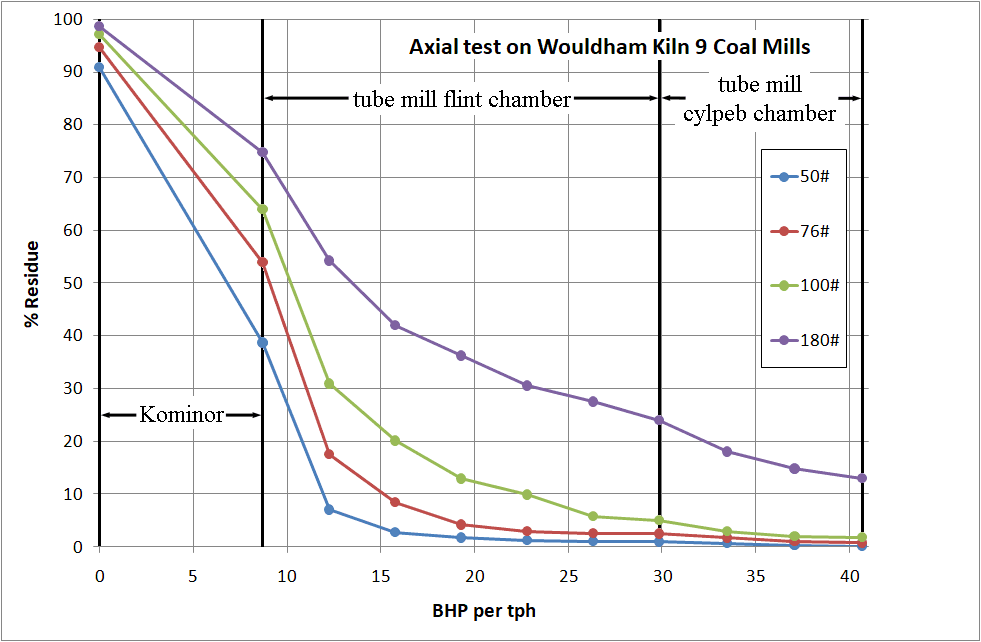
The base of the diagram is divided to represent BHP per ton ground per hour, and the vertical ordinates represent the sieve residues corresponding to the HP expended. From the general appearance of the curve representing the residue on 180#, it would appear that the flint stones were somewhat too large for fine grinding, and that the addition of metallic grinding bodies was an improvement. The average weight of the flints was 6.8 oz. and of the cylpebs, 0.9 oz.
The diaphragm plate between the flintstone chamber and the cylpeb chamber, acts somewhat as a sieve, and prevents the passage of the coarser ground coal. This will be apparent from the curve denoting the residue on 76#.
From the curve, the BHP per ton ground per hour, referred to 20% on 180#, is 32.0. This is an average figure.
Application of New Surface Theory, and of Stadlers Theory
(a) New Surface Theory
The object of the calculations is to determine the new surface produced, per BHP per hour, both by the Kominor, and by the Tube Mill.
To this end, three samples have to be examined, they are:-
(1) Coal entering Kominor
(2) Coal leaving Kominor
(3) Coal leaving Tube Mill
Each sample is divided into suitable grades; for the coarse grading sieves are used, ranging from 1 inch square mesh to a 180# sieve; for the finer grades Hall's sedimentation method is adopted.
The particle size in each grade is determined by measuring the average width of a large number of particles, the measurements being always taken in the same direction. For the coarser particles (up to and including the residue on a 20# sieve) the sample was spread out at random on a sheet of paper, ruled to ⅒" squares, and the horizontal widths of 100 particles were estimated by eye, with the assistance of a set square.
For particles passing the 20# sieve, the average width of 50, or of 100 particles, was measured horizontally by a microscope. For the purpose of calculating the new surface produced, the average width so measured is taken to be the side of a cube, and the surface of the particle is then calculated assuming it to be of cubical shape. The method is not absolutely accurate, but it is comparative. If all tests for new surface are worked out in a similar manner, then direct comparisons can be made. The subject was exhaustively examined by the U.S. Bureau of Standards, who commenced by measuring microscopically the length, breadth, and thickness of a large number of particles, the diameter of the equivalent sphere being the geometric mean of the three measurements.
It was discovered later that results nearly as accurate could be much more rapidly obtained by taking the average width of a large number of particles selected at random, such measurements being always taken in the same direction, and without reference to the actual orientation of the particle.
Formula for calculating surface in each grade
Let S = average particle width, or side of equivalent cube in inches.
W = lb of coal in grade
The specific gravity of the ground coal was found to be 1.40, hence the weight per cubic foot, reckoned solid, is 1.40 × 62.4 = 87.36 lb. The weight of one cubic particle, in lb, is:-
S3 × 87.36 / 1728 and the number of cubes in the grade is:-
W × 1728 / (S3 × 87.36)
The surface of the cubes in the grade, in square feet:-
W × 1728 / (S3 × 87.36) × 6 × S2 /144 = 0.824 × W / S
Example. Taking the residue on the 50# sieve in the results table below, the surface in the grade per 100 lb of coal is:-
0.824 × 13.45 / 0.02523 = 439 square feet
From the figures given in the following tables, it will be seen that taking 100 lb of coal, we have (in square feet):-
(1) Surface entering Kominor 3157
(2) Surface leaving Kominor 56558
(3) Surface leaving Tube Mill 220183
(4) Hence new surface produced by Kominor per 100 lb coal = 56558 - 3157 = 53401 sq ft
(5) New Surface produced by Tube Mill, per 100 lb coal = 220183 - 56558 = 163625 sq ft
Now the Kominor ground 4.318 tons of coal per hour with an expenditure of 37.64 BHP.
(6) Hence new surface produced by Kominor, per BHP per hour is 53401 × 4.318 × 22.40 / 37.64 = 137200 sq ft
The tube mill took 137.93 BHP and similarly:-
(7) New surface produced by the Tube Mill per BHP per hour is
163625 × 4.318 × 22.40 / 137.93 = 114800 sq ft
These figures lend support to the New Surface Theory assuming the efficiencies of the Kominor and tube mill to be equal.
(b) Examination of Results on the Stadler Theory
The coal is graded, and the average particle width in each grade determined, as in the case of the New Surface Theory.
The material is taken originally in the form of one inch cubes, and a unit of energy is said to be expended for each successive reduction in volume by one half. Thus to reduce the original cube of one cubic inch to cubes of ½ cubic inch, one energy unit is required. To reduce the original cubic inch to cubes of ¼ cubic inch two energy units are required. To reduce the cubes of ⅛ cubic inch, three energy units are required, and to reduce to cubes of 1/16 cubic inch four energy units are used. The particle volume is thus halved for the expenditure of each additional energy unit.
It will be found that the energy units required to crush down to cubes, to a length of side S measured in inches, is given by the formula:-
Energy value = -10 Log10S
The factor is actually 3/log10(0.5) = -9.96578
Example. Taking the residue on the 50# sieve in the results table below, the particle size is 0.02523 inches.
Log10S = -1.5986
-10 Log10S = 15.986
The Stadler units have no actual relation to the foot pound, hence the results may be expressed in a conventional manner.
In the following tables a weight of 100 lbs of coal has been taken, and the energy value of the unit in each grade has been multiplied by the actual weight of coal in the grade.
The results added together are proportional to the useful work done per 100 lbs. of coal, as estimated by the Stadler theory. Knowing the weight of coal ground per hour, and the horse power expended, a simple calculation then gives the energy units produced per BHP per hour by the Kominor, and by the tube mill.
The figures will be comparative for different tests, if the above method of working out the results is adhered to.
From the figures given in the following tables, it will be seen that taking 100 lb of coal, we have (in Stadler energy units):-
(1) Coal entering Kominor 780
(2) Coal leaving Kominor 2128
(3) Coal leaving Tube Mill 3088
Hence:
(4) Energy units supplied by Kominor = 2128 - 780 = 1348
(5) Energy units supplied by tube mill = 3088 - 2128 = 960
also
(6) Energy units supplied by Kominor per BHP per hour is
1348 × 4.318 × 22.40 / 37.6 = 3462
(7) Energy units supplied by tube mill per BHP per hour is
960 × 4.318 × 22.40 / 138.0 = 673
From lines (6) and (7) it will be apparent that the Stadler Theory over-estimates the value of the work done in coarse crushing, as compared to the work done in fine grinding, upon the assumption that the Kominor and tube mill are of equal efficiency.
Tabulation of Data on 100 lb Coal
Tables rearranged to fit web page - both analyses used the same psd data. I have corrected values that have been miscalculated or mistyped. This does not affect the qualitative conclusions drawn. For the data as typed, refer to the original.
| New Surface | Stadler Energy Units | ||||
|---|---|---|---|---|---|
| Sieve | mean size in | fraction % w/w | sq ft per 100 lb | unit energy | total energy |
| Coal entering Kominor | |||||
| 1" | 1.6 | 5.270 | 3 | -2.03 | -10.72 |
| 0.5" | 0.901 | 15.230 | 14 | 0.45 | 6.87 |
| 0.25" | 0.516 | 15.370 | 25 | 2.86 | 44.01 |
| 10# | 0.2689 | 27.350 | 84 | 5.68 | 155.47 |
| 20# | 0.0698 | 14.280 | 169 | 11.52 | 164.53 |
| 50# | 0.02523 | 13.450 | 439 | 15.93 | 214.21 |
| 76# | 0.01487 | 3.730 | 207 | 18.21 | 67.94 |
| 100# | 0.00897 | 2.440 | 224 | 20.40 | 49.78 |
| 180# | 0.00511 | 1.450 | 234 | 22.84 | 33.11 |
| balance | 0.00238 | 0.660 | 228 | 26.14 | 17.26 |
| 100s | 0.00125 | 0.641 | 422 | 28.93 | 18.55 |
| 600s | 0.00055 | 0.043 | 64 | 32.48 | 1.40 |
| 3600s | 0.00007 | 0.079 | 930 | 41.41 | 3.27 |
| 21600s | 0.00005 | 0.007 | 115 | 42.86 | 0.30 |
| Total | 100.000 | 3158 | 765.98 | ||
| Coal leaving Kominor | |||||
| 10# | 0.133 | 0.400 | 2 | 8.73 | 3.49 |
| 20# | 0.062 | 7.750 | 103 | 12.03 | 93.27 |
| 50# | 0.0234 | 30.610 | 1078 | 16.25 | 497.48 |
| 76# | 0.0137 | 14.630 | 880 | 18.57 | 271.67 |
| 100# | 0.00769 | 10.580 | 1133 | 21.07 | 222.90 |
| 180# | 0.00457 | 10.970 | 1978 | 23.32 | 255.83 |
| balance | 0.00262 | 3.750 | 1179 | 25.73 | 96.48 |
| 100s | 0.00155 | 10.470 | 5565 | 28.00 | 293.17 |
| 600s | 0.00048 | 6.550 | 11242 | 33.07 | 216.63 |
| 3600s | 0.00011 | 4.150 | 31080 | 39.45 | 163.72 |
| 21600s | 0.00005 | 0.140 | 2307 | 42.86 | 6.00 |
| Total | 100.000 | 56546 | 2120.64 | ||
| Coal leaving tube mill | |||||
| 76# | 0.0149 | 0.790 | 44 | 18.21 | 14.38 |
| 100# | 0.00967 | 0.980 | 83 | 20.08 | 19.68 |
| 180# | 0.00442 | 11.210 | 2089 | 23.47 | 263.05 |
| balance | 0.00250 | 5.230 | 1723 | 25.93 | 135.62 |
| 100s | 0.00171 | 23.090 | 11124 | 27.58 | 636.72 |
| 600s | 0.00068 | 40.330 | 48859 | 31.57 | 1273.08 |
| 3600s | 0.00010 | 17.790 | 146556 | 39.86 | 709.17 |
| 21600s | 0.00005 | 0.580 | 9556 | 42.86 | 24.86 |
| Total | 100.000 | 220035 | 3076.54 | ||
Sieves used on Grinding Plant Research
On the face of it, this item shouldn't be worth including. OK, so they bought some new sieves - evidently a rare occurrence. However, the data, and the conclusions drawn, say something significant about the way BPCRA worked.
New 100# and 180# sieves were recently purchased from 2 different sources designated A & B respectively.
The aperture widths of each sieve, and the wire diameters were subsequently examined under a microscope. The results are given in the tables below. To avoid decimals the aperture widths, and the wire diameters, are given in units of 1/10,000 inch. About 216 apertures and 196 wire diameters were measured on each sieve.
100# Sieves. Referring to the sieve A, it will be seen that the aperture width varied from 55 to 78. The percentage number of each aperture width is given. Thus 13 per cent of the apertures measured, were of the correct size, viz.68, and 29% of the wires measured were of the correct diameter, viz. 32.
Similar results were obtained from the 100# sieve B.
180# Sieves. The standard aperture width is 37.5. The average width in the case of the sieve A was 36.9 and for sieve B 35.1.
To find the effect of the variation of aperture width on the sieve test results, some siftings were made on finely ground standard sand, with the following result.
Sieve B. Residue on 180# 3.42, 3.40, 3.40, 3.40: average 3.40
Sieve A. Residue on 180# 2.68, 2.68, 2.64, 2.66: average 2.66
The 180# sieve A was subsequently adopted as a standard.
I have not included the large tables of dimension readings. Suffice it to say that the results (in 1/10,000 inch units) were:
100# sieve A: wire diameter 31.7±3.9: aperture 67.7±7.1 (2s error margins)
100# sieve B: wire diameter 30.4±4.4: aperture 68.5±7.1
180# sieve A: wire diameter 18.1±2.8: aperture 36.7±7.0
180# sieve B: wire diameter 19.4±2.9: aperture 34.8±6.6
In 1904, there was no general specification for test sieves. In that year, the British Standard for Portland cement (BS 12) was published and it laid down specifications for the test sieves used in characterising Portland cement. Before 1904, there had existed an informal sieve specification, based upon the proposals for test methods suggested by David Butler in 1899. In this specification, the 100# sieve had wire diameter 0.0032" and an aperture of 0.0068" (172.7 μm). The 180# sieve had wire diameter 0.0018" and an aperture of 0.003756" (95.4 μm). In BS 12, these sieves were considered too flimsy, and heavier wire gauges were specified. The 100# sieve had wire diameter 0.0040" and an aperture of 0.0060" (152.4 μm). The 180# sieve had wire diameter 0.0020" and an aperture of 0.003556" (90.3 μm). In this BPCRA investigation, the "standard" apertures were stated to be 0.0068" for 100# and 0.00375" for 180#, and they accordingly selected as "standard" the sieves most close to those values, and rejected the one that, in fact, met British Standards. Maybe BPCRA did not have a copy of BS 12. Or maybe they did and chose to - or were made to - ignore it. In view of the fact that all the sieve analyses produced showed the sieves were consistently out of calibration, it becomes clear that nothing they did in terms of particle size analyses was reliable.
TESTS ON 18" × 18" EXPERIMENTAL TUBE MILL
This batch mill, which could grind 15-20 kg of cement, remained in use for many decades. Leighton Buzzard sand, graded to -850+570 μm, was used as a test material of constant hardness.
The object of experimenting in the first instance was to ascertain:-
(1) The best type and size of grinding media
(2) The best ratio between the volume of the material being ground, and the volume of the interstices between the grinding mediums
(3) The best speed at which to operate the mill.
It is probable that the best type of grinding medium can be discovered by the 18" mill, but the best size to use may depend to some extent on the diameter of the mill, and the material under treatment.
It is thought that the best speed for tube mills of all sizes can be largely estimated from experiments made on the small mill.
The 18" mill in question has no feed or discharge openings. The material under treatment is inserted at the commencement of the experiment and the rate of grinding is examined from time to time by stopping the mill, and obtaining samples through the manhole door.
Steel balls as grinding media
The first series of experiments were made with hard steel balls of 1" initial diameter.
Volume of Interstices
The charge of 300 lb of steel balls was put into the mill, which was then run for a short time. Water was next poured in until the surface of the water coincided with the average level of the surface of the charge. The resulting calculations are as follows:-
(1) Charge volume (as measured in mill, cu in) = 1793
(2) Water added, cu in = 780
(3) % voids = 780 × 100 / 1793 = 43.5
(4) Depth of surface of charge below centre line = 1.30"
TEST No.1
Ratio of sand to voids 115%.
After drying out the mill, the charge of 300 lb of 1" dia. steel balls was replaced, together with 48.81 lb of dry standard sand, which had been screened through 20# sieve, and retained on 30# sieve.
Speed of Mill. The exact internal diameter being 17.85" the speed was taken in the first instance as 200/√17.85 = 47.0 rpm.
For inch units, critical speed is given by 265.3/√D, so this formula, which was commonly used at the time, represents 75% critical.
The mill being fitted with lifter bars cast on to the lining plates, thus preventing any slip, it was not considered desirable to run the mill faster, until speed trials had been made. The sieve test results were erratic during the early portion of the test, .so that runs of only 150 revolutions were at first made between the sieve tests, later on the results became more uniform, and periods of 300 revolutions were adopted.
On plotting down the sieve residues in diagram form it was found that 4100 revolutions were required to reduce the residue to 5 per cent on 180#. Now the charge of sand in the mill was 48.81 lb, and since the mill at 47 rpm makes 60 x 47 = 2820 revolutions per hour, it is evident that the equivalent quantity of sand ground (lb/hr) is 48.81 × 2820 / 4100 = 33.6
The actual horsepower supplied for grinding, after deducting motor losses was 0.850, hence the BHP per ton ground per hour is 2240 / 33.6 × 0.850 = 56.7
Subsequent tests
Three further tests were made with the 1" dia. steel balls, the ratio of sand volume to interstices being 100, 55 and 35% respectively. The sand volume is that measured at the beginning of the test. To estimate the increase of sand volume after grinding, the weight of the contents of a small platinum crucible was taken (1) when filled with grit sand, and (2) when filled with the ground sand. The increase of volume was about 36%.
The test results are given in the table below:-
| Test | 1 | 2 | 3 | 4 |
|---|---|---|---|---|
| Date | 27/03/1920 | 14/04/1920 | 20/04/1920 | 29/04/1920 |
| Charge of sand, lb | 48.81 | 42.44 | 23.31 | 14.81 |
| sand / voids % | 115 | 100 | 55 | 35 |
| revs for 5% on 180# | 4100 | 3405 | 1955 | 1470 |
| average rpm | 46.90 | 47.03 | 46.85 | 46.72 |
| actual BHP supplied | 0.850 | 0.928 | 0.882 | 0.863 |
| output lb/hr: standard speed | 33.6 | 35.1 | 33.6 | 28.4 |
| BHP per ton per hour | 56.7 | 59.1 | 58.8 | 68.0 |
| sand volume increase % | 35.4 | 36.7 | 35.6 | 35.7 |
Weight of 1" dia. steel balls = 2.35 oz.
NOTE. All calculations are referred to grinding to 5% on 180#.
The graphs for each test, as regards the residues on 180#, are shown below.
Apparently the original volume of sand may vary from 55% to 115% of the volume of the interstices, without much affecting either the quantity ground per hour, or the horse-power required.
Tests on 18" Mill using Cylpebs
Four tests were made with cylpebs, using different percentages of sand in each case. The speed was 47 rpm as before.
Details of Cylpebs
Average length = 1.27"
Average Diameter = 0.70"
Average weight = 2.15 oz
Weight of charge = 300 lb
Surface of charge 1" below centre line of mill.
% Voids
The cylpebs being put into the mill, and the surface levelled, the charge volume as measured in position, was 1888 cu in. Water was then poured in, and 830 cu in were required to fill the voids. Hence % voids = 830 × 100 / 1888 = 44.0
Weight of standard sand
The average value is found to be 93.8 lb per cu ft with moderate shaking. Hence weight of sand for 100% voids = 830 × 93.8 / 1728 = 45 lb
Tests Made
Four tests were made, Nos. 5, 6, 7 and 8, corresponding to 115, 100, 55 and 35% sand respectively. A summary is as follows:-
| Test | 5 | 6 | 7 | 8 |
|---|---|---|---|---|
| Date | 27/03/1920 | 14/04/1920 | 20/04/1920 | 29/04/1920 |
| Charge of sand, lb | 51.75 | 45.00 | 24.75 | 15.75 |
| sand / voids % | 115 | 100 | 55 | 35 |
| revs for 5% on 180# | 5700 | 4520 | 2270 | 1540 |
| average rpm | 46.75 | 47.02 | 46.60 | 46.85 |
| actual BHP supplied | 0.911 | 0.897 | 0.845 | 0.857 |
| output lb/hr: standard speed | 25.6 | 28.1 | 30.7 | 28.8 |
| BHP per ton per hour | 79.7 | 71.6 | 61.6 | 66.6 |
The graphs for each test, as regards the residues on 180#, are shown below.
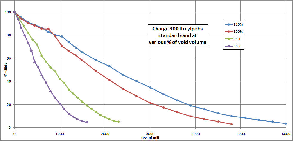
The results may be compared with those obtained for steel balls, see above. Apparently the steel balls are better suited for a wide range in the percentage of sand present. The cylpebs used were new, and with sharp edges; perhaps better results would be obtained when the edges became well rounded. It is also thought that cylpebs might show relatively to more advantage with a smooth mill lining. During the present tests lifter bars are in use.
Speed trials on 18" grinding mill
During the preceding trials on the 18" mill, the speed used has been in accordance with the formula N = 200/√D where N = mill rpm and D = diameter inside lining of mill, in inches. The exact internal diameter of the 18" mill being 17.85", the calculated rpm is N = 200/√17.85 = 47.3
The value of the constant in the formula, i.e. 200, may be said to represent average practice for mills with smooth lining plates.
At the suggestion of Mr Blyth, trials have recently been made at speeds approximately 10% higher, and 10% lower than the above.
At present the lining plates of the 18" mill are provided with lifter bars, "slip" being thus prevented, and a somewhat lower speed of revolution than that necessary for smooth lining plates might therefore be expected.
It has not yet been demonstrated that the above formula is satisfactory for smooth lining plates. It gives too high a value for the speed of revolution when dealing with ribbed lining plates, and cylpebs.
The results so far obtained are as follows:- (1) Charge in mill: cylpebs; 300 lb (2) Standard sand used
| Test | 13 | 14 | 15 | 16 | 17 |
|---|---|---|---|---|---|
| Charge of sand, lb | 45.00 | 45.00 | 33.75 | 45.00 | 31.50 |
| sand / voids % | 100 | 100 | 75 | 100 | 70 |
| revs for 5% on 180# | 4480 | 5280 | 4110 | 3540 | 2380 |
| average rpm | 47.1 | 51.8 | 51.6 | 43.7 | 43.8 |
| actual BHP supplied | 0.819 | 0.863 | 0.913 | 0.817 | 0.859 |
| output lb/hr | 28.4 | 26.5 | 25.4 | 33.3 | 34.8 |
| BHP per ton per hour | 64.6 | 73.0 | 80.4 | 54.9 | 55.3 |
It will be seen that the low speed trials gave the best result both as regards output and power.
The ratio of sand to voids given, is that obtaining at the commencement of the experiment, i.e. with standard sand through 20#, and retained on 30#. When the sand is ground to 5% residue on 180# its volume increases by approximately 36%., hence a ratio sand to voids of 100% becomes finally 136%, and a ratio sand to voids of 70% becomes finally 95%.
Repeat Test
To gain some idea as to the accuracy of the results obtained, Test No.6, made on cylpebs, with 100% sand at 47 rpm was repeated, the result being Test No.13 in the present report.
The comparison is as follows:-
| Test | 6 | 13 |
|---|---|---|
| sand / voids % | 100 | 100 |
| revs for 5% on 180# | 4520 | 4480 |
| average rpm | 47.0 | 47.1 |
| actual BHP supplied | 0.897 | 0.819 |
| output lb/hr | 28.1 | 28.4 |
| BHP per ton per hour | 71.6 | 64.6 |
There is a close agreement between the revolutions required to grind to 5% on 180# in each case, but some difference in the BHP required. The cause of the latter is being investigated.
30" x 72" Experimental Mill
The design for the above mill has now been completed. It is provided with continuous feed and discharge arrangements, and can be used either for wet or dry grinding.
It is proposed to use in this mill grinding media which the experiments on the 18" mill have shown to be satisfactory, and to experiment in the first instance with various types of discharge arrangements. Periphery ports are provided, also two types of end delivery plates; the latter admit of a central delivery, or a discharge through various arrangements of ports in the end plate which are arranged between the centre and the circumference of the mill. A series of cover plates are provided so that any, or all the ports, may be blanked off as required.
The mill has cast iron renewable lining plates, which may be used with or without lifter bars.
To eliminate the effect of friction ball bearings are used throughout.
CHEMICAL DEPARTMENT
Setting Time of Cement
The object of this research is to discover the cause of changes in the setting time of cement, on storage, or in transit, and to test the correctness of a theory that these changes are brought about by the absorption of moisture from the atmosphere, or its displacement by equivalent molecules of carbon dioxide, derived from the same source.
It is suggested that the time of setting is regulated by the amount of water combined with the cement, whereby some or all the particles are hydrated on the surface and are thus surrounded by a film or sheath of hydrated salt (probably aluminate) which resists or delays the penetration of gauging water to the interior of such particles.
Hydrated cement is readily attacked by carbon dioxide and it is suggested that the quickening of setting time, which frequently takes place on exposure of the material to air, is due to the combined water in the hydrated sheath or coating referred to, being displaced wholly or in part by carbon dioxide, thus destroying or altering the film, so that water may readily penetrate and hydrate the particles.
This is opposed to the theory, often advanced, that changes in setting time are brought about by chemical or physical changes in the character of the cement itself.
It is well known that untreated cement, ground from pure clinker, more frequently has a practically instantaneous set, even when gauged with a large excess of water; whereas the same cement, if steamed in the tube mill during grinding and/or treated with gypsum may be regulated to almost any reasonable setting time, although the proportion of water taken into combination during the process is comparatively small.
The question of the action of gypsum in regulating the setting time of cement is reserved for the present, but it may be pointed out that the water of crystallization present in gypsum (CaSO4.2H2O) appears to be essential, as it is generally considered that dead-burned calcium sulphate has no retarding action. It has also been observed that cement ground with gypsum alone requires a greater quantity of the retarder to attain a given setting time, than if ground with gypsum plus water or steam.
Gypsum loses three-fourths of its water of crystallization at a comparatively low temperature (120° - 130° C) and the frictional heat of cement, generated in the tube mill, is theoretically about 159° C.
For the purposes of the present researches, samples of rotary, Schneider and chamber kiln cements; each prepared in three different ways, are being experimented with.
The methods of preparation are:-
Class (a): Cements ground with gypsum only
Class (b): Cements ground with gypsum and steam
Class (c): Cements ground from clinker untreated in any way.
These nine cements are to be examined as follows:-
1. Analysis, including the separation of the constituents lost on ignition
2. Fineness
3. Setting time, under standard conditions of temperature and percentage of gauging water. Also at "Normal Consistency"
(a) as received
(b) after exposure to air for 24 hours
(c) after storage out of contact with air.
4. Effect on the setting time of exposure of the cement to:-
(a) Pure dry air
(b) Pure dry oxygen
(c) Dry carbon dioxide
(d) moist air, free from carbon dioxide
(e) moist oxygen, free from carbon dioxide
(f) moist carbon dioxide
(g) moist air, followed by carbon dioxide.
5. Determination of the percentage of carbon dioxide and water, before and after each experiment; and the relation between the setting time changes (if any) and the amount of these constituents absorbed or lost.
6. Effect on setting time of additions of soluble carbonates, sulphates and nitrates and organic substances.
7. Anything arising from the foregoing.
8. Tensile strength of the samples.
9. Soundness.
Up to the present 3 samples of class (b) have been partially examined in accordance with the above programme. The composition of the samples, as received, was as below:-
| 1 Rotary | 2 Schneider | 3 chamber | |
|---|---|---|---|
| Silica | 22.48 | 21.33 | 21.53 |
| Insoluble residue | 0.28 | 0.64 | 2.03 |
| Alumina | 7.17 | 7.68 | 7.20 |
| Ferric Oxide | 2.25 | 2.30 | 3.00 |
| Lime | 63.06 | 62.88 | 60.46 |
| Magnesia | 1.73 | 1.01 | 1.45 |
| Sulphuric anhydride | 0.64 | 0.93 | 0.79 |
| Sulphides | 0.00 | 0.00 | tr |
| Carbon dioxide | 0.23 | 0.97 | 1.03 |
| Combined water | 1.80 | 2.09 | 2.09 |
| Carbon | 0.00 | tr | 0.04 |
| (balance) | 0.36 | 0.17 | 0.38 |
| Total | 100.00 | 100.00 | 100.00 |
| Loss on ignition | 2.02 | 3.19 | 3.20 |
| Residue on 180# | 9.6 | 15.0 | 14.0 |
The term labelled "(balance)" was actually labelled "Potash and soda", but the latter were not determined. The fact that "alkalis" are merely a balancing item shows that analytical techniques of a professional standard had yet to be implemented. One might suggest that, in a study of setting times, the actual alkalis were quite important, but this was not appreciated at the time. In fact it is fairly obvious that the objective of the project was to pin the blame for setting time problems on the cement's subsequent treatment, rather than its original composition.
For setting time, in minutes, air, cement and water were at 60°F, and 25% water was used.
For setting time after storage out of contact with air, the samples were stored in a sealed bottle, for 120 days. One set kept in the laboratory, where the temperature ranged from 55° to 70°F; and another set kept in a room in which there was no artificial heat, the temperature of which ranged from 40°F to 67°F during the period of storage.
For exposure of the cement to various gases, 140 grams of cement were enclosed in a large tube, spread out in a thin layer over the whole length of the tube (24 inches), and a current of the gas passed over it during a period of about 24 hours. The volume of gas was, in every case, 20 litres.
The arrangements for purifying the gases, varied, of course, with the character. In the case of dry air, for instance, the air from an aspirator was first passed through strong sulphuric acid to remove any ammonia fumes; then through successive gas-washing bottles containing strong caustic potash and caustic soda to remove carbon dioxide. The air then passed through lime water, which served to check the efficiency of the previous treatment, and finally through towers filled with soda lime, and calcium chloride, in which all moisture was abstracted before it entered the tube containing the cement. At the exit end of this tube, guard tubes filled with soda lime and calcium chloride prevented the accidental ingress of un-purified air.
Setting time results:-
| 1 Rotary | 2 Schneider | 3 chamber | |
|---|---|---|---|
| as received, init | 151 | 84 | 46 |
| as received fin | 262 | 141 | 130 |
| after 24 hrs aeration, init | 16 | 27 | 45 |
| after 24 hrs aeration, fin | 23 | 75 | 76 |
| after 120 days at 55-70°F, init | 157 | 61 | 40 |
| after 120 days at 55-70°F, fin | 287 | 170 | 113 |
| after 120 days at 40-67°F, init | 200 | 80 | 44 |
| after 120 days at 40-67°F, fin | 322 | 193 | 122 |
Setting before and after exposure to various atmospheres:-
| Cement | Gas °F | cement CO2 | cement H2O | Setting time | |||||
|---|---|---|---|---|---|---|---|---|---|
| before | after | before | after | before | after | ||||
| init | fin | init | fin | ||||||
| Exposure to dry air, free from CO2 | |||||||||
| 1 | 58 | 0.25 | 0.27 | 1.90 | 1.85 | 153 | 288 | 153 | 286 |
| 2 | 58 | 1.08 | 1.06 | 2.27 | 2.23 | 65 | 115 | 63 | 125 |
| 3 | 59 | 1.04 | 1.06 | 2.11 | 2.08 | 52 | 110 | 51 | 121 |
| Exposure to ordinary air | |||||||||
| 1 | 64 | 0.29 | 0.34 | 2.28 | 2.16 | 128 | 296 | 13 | 22 |
| 2 | 59 | 1.03 | 1.06 | 2.34 | 2.30 | 51 | 174 | 38 | 128 |
| 3 | 62 | 1.11 | 1.12 | 2.15 | 2.12 | 46 | 100 | 46 | 83 |
| Exposure to moist air, free from CO2 | |||||||||
| 1 | 66 | 0.26 | 0.22 | 1.80 | 1.90 | 106 | 244 | 196 | 395 |
| 2 | 61 | 1.01 | 1.00 | 2.26 | 2.52 | 98 | 183 | 85 | 225 |
| 3 | 65 | 1.34 | 1.29 | 1.92 | 2.01 | 50 | 130 | 72 | 175 |
| Exposure to dry oxygen, free from CO2 | |||||||||
| 1 | 59 | 0.26 | 0.27 | 1.93 | 1.98 | 116 | 266 | 122 | 266 |
| 2 | 58 | 1.07 | 1.06 | 2.22 | 2.24 | 51 | 160 | 51 | 167 |
| 3 | 62 | 1.05 | 1.04 | 2.24 | 2.20 | 65 | 148 | 61 | 145 |
| Exposure to dry CO2 | |||||||||
| 1 | 70 | 0.28 | 0.41 | 2.30 | 2.24 | 94 | 248 | 8 | 14 |
| 2 | 69 | 0.97 | 1.21 | 2.29 | 2.21 | 52 | 155 | 18 | 103 |
| 3 | 62 | 1.54 | 1.82 | 2.24 | 2.22 | 50 | 132 | 29 | 84 |
The probable experimental error, in determining combined water or carbonic anhydride in cement, has been found to be 0.02% hence absorptions or losses of the order of 0.02% cannot be regarded as possessing any significance.
The probable experimental error of the setting times might have been more pertinant.
For instance No.1 cement, when exposed to dry air free from carbonic anhydride, is shown to have absorbed 0.02% of the latter compound; but as this figure is equal to the probable error of analysis, it should be ignored.
The experiments already made show:-
(1) that the setting time of the cements examined whether made in the rotary kiln, Schneider kiln, or chamber kiln is not materially affected by exposure of the substance to dry air or oxygen, free from carbon dioxide.
(2) on exposure to ordinary air or to dry carbon dioxide, cement absorbs the latter, which displaces combined water, and the setting time is accelerated, although the proportion of carbon dioxide absorbed, or combined water displaced, is relatively very small. For instance, in the case of No.1 cement, exposed to ordinary air the percentage of carbon dioxide absorbed from 20 litres of air, during the experiment, was only 0.05% and that of the combined water displaced or lost 0.12% yet the setting time was reduced from 128 minutes to 13 minutes, initial, and from 296 minutes to 22 minutes final.
(3) on exposure to moist air, free from carbon dioxide, cement absorbs water, and the setting time is lengthened considerably, in proportion to the amount of water absorbed.
(4) The setting time is not materially altered, when cement is stored for four months in sealed or air-tight receptacles.
In paragraphs (2) and (3) it is stated that cement exposed to air will abstract and absorb any carbon dioxide or water vapour present. Hence it is expected that the setting time of cement exposed to ordinary atmospheric air will be accelerated or retarded according to the relative amounts of these two substances absorbed. If the air to which the cement is exposed be damp, the moisture absorbed may over-ride the carbon dioxide also taken up, and the setting time thus retarded. On the other hand, if the air be dryer, the absorbed carbon dioxide may overbalance the water, and the setting time be accelerated.
The experiments are being continued, with further samples of cement, but using a larger volume of air or gas per gram of cement treated. In the experiments described, the volume of gas was 143 cm3 per gram of cement. This has now been increased to 350 cm3 per gram.
Elutriation tests
Assistance has been rendered to the grinding plant research by elutriation tests on a number of finely ground coal samples, and the widths of several hundred particles have been measured microscopically, in order to enable the new surface produced to be calculated.
Other chemical work
Numerous analyses of coal, slurry and kiln gases etc., have been made in connection with the kiln tests from time to time. The calorific value of a large number of coal samples, sent up from various works has been tested on the Sarco bomb calorimeter and the results reported to the works concerned. Analyses have also been made of firebrick linings for rotary kilns, and of a few raw materials.