Approximate clinker production: 21 million tonnes (22nd)
Raw materials:
Upper Chalk (Seaford Chalk Formation: 85-88 Ma) by rail from nearby quarries.
Various clays:
1877-1915 Alluvial Clay from the Medway estuary (Upchurch & Stoke)
1909-1920: Alkerden London Clay (London Clay Formation: 48-55 Ma) 560200,173100 (Swanscombe) slurried at the clay quarry and pumped to the main washmills at the chalk quarry.
1915-1939 Thames Alluvial Clay from Higham Saltings 570500,175900
1920-1964 London Clay (London Clay Formation: 48-55 Ma) from Bean 558700,171800
1922-1938: Alluvial Clay from the waterfront 558000,175100
1939-1971 Alluvial clay by river tanker from Cliffe 571400,177100 (50:50 with Bean clay 1953-1963)
The London clay was used primarily for uncallowing purposes.
On the 1872 map, there was a quarry on the site, with a tramway leading to what became “Johnson’s Wharf”, for supplying chalk ballast. It was claimed by Johnson to be one of the oldest chalk ballast quarries on the Thames, and it had previously supplied I. C. Johnson’s plant at Gateshead. Johnson bought the freehold around 1875, and had a plant with 15 Johnson kilns in operation by 1877 (rated output 350 t/week). The number of chamber kilns rose to 54 before rotary kilns were installed. The rough sequence of expansion was as follows:
Kilns 1-15: 1877-1911: 350 t/week
Kilns 16-22: 1881-1916: 200 t/week
Kilns 23-30: 1888-1924: 185 t/week
Kilns 31-33: 1890-1911: 90 t/week
Kilns 34-41: 1896-1924: 190 t/week
Kilns 42-45: 1898-1924: 90 t/week
Kilns 46-54: 1901-1924: 215 t/week
All these had (according to Johnson) heat consumption ~10.6 MJ/kg. This oft-quoted figure is undoubtedly an under-estimate, referring only to “flat-out” production. Since capacity utilization was typically 60-70%, normal heat consumption was probably much nearer the 14 MJ/kg typical of chamber kilns.
The company was part of the APCM amalgamation in 1900, but dropped out, as did West Kent and Weekes. The departure of Johnson’s caused particularly bad feeling, since the company was a major player, and its directors had been much involved in the project. The company tried hard to repair relations with APCM, and after the BPCM takeover, it played a major part in the new company. The plant was described in detail in the BPCM 1924 schedule. Because of its significant chalk land holdings, the plant remained an important part of Blue Circle’s Thames-side operation. Kilns A4-A7 demonstrated a commitment to aggressive expansion, and A6 and A7 were Britain’s largest kilns until overtaken by West Thurrock A6 in 1934, providing Vickers Armstrong with a successful design that was subsequently installed at many other locations. The addition of kilns 6 and 7 also made the plant Britain's largest from 1930 (overtaking Bevans) to 1933 (after which it was overtaken by West Thurrock). The plant became too cramped for further expansion after this. Johnson’s 91 m brick stack, constructed originally for the chamber kilns in 1877, remained in use until closure. The plant made sulfate resisting clinker alongside ordinary clinker from the late 1940s to 1971. The plant was the first on Thames-side (1933) to fit electrostatic precipitators.
Initially relying solely on its wharf for shipping, a rail link was established from the 1900s, but water transport remained important for despatch of product. After closure, the site was re-developed. Johnson’s Wharf, originally used for chalk export, is still in use, ironically for intake of aggregates for a Lafarge ready-mix plant. The plant site is largely under a housing estate. The original quarry is now a small park, and the site of the old stack, once the tallest in southern England, is preserved on a small mound. The main chalk quarry became the Western Quarry for Northfleet, and is now occupied by the Bluewater Retail Park.
The initial plant is described in an article in Building News. The progressive development of the plant is described in a further articles in 1902, in 1908 and in 1930.
Power Supply
The plant was originally directly driven by steam engines. Around 1905, steam power was replaced with direct-drive gas engines. The 1907 rotary kilns were electrically driven, the power produced by generators driven by gas engines. In 1923, some of the finish mills were electrified, and these and the kiln section were supplied with electricity from the Kent power house. In 1925, the rest of the plant was electrified, and both Kent and Johnsons were fed by the Kent power house, augmented with two more turbo-generators. In 1955, both plants were switched to grid electricity.
Rawmills
Washmills were used, located at various places around the plant site, fed with chalk brought by rail from the quarry and clay by rail from the wharf. While the Bean clayfield was in operation, clay was washmilled there, and pumped to the plant. The rawmills evolved with increasing kiln capacity, as follows:
1877: two parallel washmills (? 15’ - ?30 kW each) fed with raw chalk and clay, followed by two, and ultimately six flat stone mills (20-25 kW each).
1907: two parallel sets of rough- and intermediate 18' washmills fed with raw chalk and clay, followed by three 5' screening mills.
1921: one 17'9" washmill ground clay: one rough- and one intermediate 18' washmill fed with raw chalk and clay slip, followed by two 24' screening mills.
1928: two 30’ (168 kW) washmills. Larger grit was removed from the washmill product by eight vibrating screens, then the fine slurry was distributed between four 261 kW tube mills. The screen oversize was passed to two 22 kW screening mills, with the fine product returning to the main washmills. Material rejected by the washmills and screening mills entered an elaborate flint handling system.
Seven rotary kilns were installed:
Kiln A1
Supplier: FLS
Operated: 4/1907-1921
Process: Wet
Location: hot end 558059,174799: cold end 55093,174798: entirely enclosed.
Dimensions: metric 34.00 × 2.100
Rotation (viewed from firing end): clockwise.
Slope: 1/25 (2.292°)
Speed: 1.0-2.0 rpm
Drive: about 35 kW: a single 142 kW motor droves all three kilns and coolers
Kiln profile: 0×2100: 34000×2100: Tyres at 1475, 12010, 25970: Turning gear at 12905.
Cooler: “Double-back” concentric rotary metric 9.30 × 1.200 / 1.050 / 1.650 beneath the kiln.
Cooler profile: 0×1200: 3600×1200: 3600×1050: 8850×1050: 9300×1650: 3900×1650: tyre at 2100 with trunnion end bearing: turning gear at tail end.
Fuel: Coal
Coal Mill: indirect: drier, Kominor and tube mill common to kilns 1-3.
Exhaust: via dry drop-out chambers direct to stack.
Typical Output: 57 t/d
Typical Heat Consumption: 9.05 MJ/kg
Kiln A2
Operated: 4/1907-1921
Location: hot end 558059,174793: cold end 55093,174792: entirely enclosed.
Identical in all respects to A1
Kiln A3
Operated: 4/1907-1921
Location: hot end 558059,174787: cold end 55093,174786: entirely enclosed.
Identical in all respects to A1
Kiln A4
Supplier: Ernest Newell
Operated: 1913-1966
Process: Wet
Location: hot end 557936,174817: cold end 557875,174829: hot end enclosed.
Dimensions: 202’0” × 10’0”B / 8’6”CD (metric 61.57×3.048/2.591)
Rotation (viewed from firing end): clockwise
Slope: 1/25 (2.292°)
Speed: 0.76/0.95 rpm
Drive: 48 kW
Kiln profile:
Fuel: Coal 1913-1960: Oil 1960-1966
Coal Mill: initially indirect: separately heated drier, Kominor and three tube mills. By 1924, the tube mills had been converted to two-chamber operation, and the Kominor was abandoned. Later (1929) believed to have been direct: British Rema ring-roll mill.
Exhaust: initially direct to stack. From 1933, via ID fan and electrostatic precipitator.
Typical Output: 1913-1930 169 t/d: 1930-1960 214 t/d: 1960-1966 219 t/d
Typical Heat Consumption: 1913-1930 8.61 MJ/kg: 1930-1960 7.43 MJ/kg: 1960-1966 7.48 MJ/kg
Kiln A5
Supplier: Vickers
Operated: 1921-1966
Process: Wet
Location: hot end 557934,174810: cold end 557874,174822: hot end enclosed.
Dimensions: 202’0” × 9’10½”B / 8’10½”CD (metric 61.57×3.010/2.705)
Rotation (viewed from firing end): clockwise
Slope: ?
Speed: ?
Drive: 48 kW
Kiln profile: 0×2375: 2972×3010: 15164×3010: 16231×2705: 61570×2705: Tyres at 1372, 17221, 35509, 53797.
Cooler: rotary 82’6”× 8’5”/ 6’4” (metric 25.15×2.565/1.930) at right angles to kiln
Cooler profile: 0×2083: 1067×2565: 5029×2565: 6401×1930: 25146×1930: Tyres at 3810, 18796.
Fuel: Coal 1921-1960: Oil 1960-1966
Coal Mill: Initially indirect, using kiln 4 coal system, From 1929, believed to have been direct: British Rema ring-roll mill.
Exhaust: initially direct to stack. From 1933, via ID fan and electrostatic precipitator.
Typical Output: 1921-1930 212 t/d: 1930-1960 235 t/d: 1960-1966 225 t/d
Typical Heat Consumption: 1921-1930 9.00 MJ/kg: 1930-1960 7.65 MJ/kg: 1960-1966 7.52 MJ/kg
Kiln A6
Supplier: Vickers Armstrong
Operated: 1928-27/03/1971
Process: Wet
Location: hot end 557914,174777: cold end 557823,174796: entirely enclosed.
Dimensions:
I C Johnson was a pioneer of the cement industry, and, following his emulation of William Aspdin's original product at Swanscombe, he established plants in his own right: Crown (1851), which was the first on the Medway, then Cliffe Creek (1854), then on William Aspdin's bankruptcy in 1856, he took over the Gateshead plant. He re-located to Tyneside for the next 25 years, becoming Mayor of Gateshead, and concentrated his efforts on developing the Johnson Chamber Kiln there. The Gateshead plant grew fairly large by the standards of the day, and its initial raw material - waste chalk ballast - soon ran out. Johnson then sourced a reliable chalk supply in Kent, eventually buying the quarry at Stone, and using Tyne coal ships to bring the chalk as a "return load". The logic of making clinker at the chalk source soon became unanswerable, and he decided to build a plant there. Sensibly, he reasoned that the new plant should be large from the outset, and incorporate all the best practices that he had absorbed in his long career. The result was the Greenhithe plant which opened in 1877. Johnson, now aged 70, moved back to the Thames and ran his business from there for the rest of his life.
As an unusually well-conceived plant, Johnsons naturally remained a major producer, advancing prudently but effectively with each technological innovation. It was finally killed off in 1971 by the ill-fated Northfleet project. Its main chalk quarry is now occupied by the Bluewater Retail Park.
The following is a transcript of an anonymous article in Building News and Engineering Journal, 2/7/1880 pp 5-7, believed to be out of copyright. It describes the plant in essentially its initial state, a few years after it was commissioned. While not necessarily written by Johnson, the words are undoubtedly mostly his own, in terms he used elsewhere.
Note on Imperial units of the time: 1 ton = 1.016047 tonnes: 1 ft = 0.304799 m: 1 in = 25.4 mm: 1 h.p. = 0.7457 kW.
AN IMPROVED CEMENT MANUFACTORY.
From the somewhat crude and incomplete factory of Aspdin (Note A1), established at Wakefield more than half a century ago (Note A2), there has been through all these years but indifferent and unsatisfactory progress in improvements, either to cheapen the cost or better the quality of Portland cement. While England, from its favourable position both as regards the command of raw materials (chalk and clay) and fuel at a low cost, assisted by cheap and ready means of transit to every quarter of the globe, secured a monopoly of the trade, but little anxiety or desire arose for changing the original system of manufacture (Note A3). In addition to those advantages named, a belief existed that Portland cement could only be made from chalk and clay, or mud from the river Medway, in Kent; and to such an extent did this idea prevail, that the early cement makers, in Germany especially, used Medway mud at a very high cost for their first essays in their desire to produce Portland cement. The eminent chemists, however, who soon took charge of the cement question on the Continent, were not long in disabusing the public mind on this point, and it was soon made evident that a good and reliable Portland cement could be produced from other minerals than chalk and clay. This knowledge, accompanied by equally cogent commercial reasons, led to the establishment of foreign Portland cement works, more especially in Germany; and the considerable trade hitherto done with that country by English manufacturers has in consequence dwindled down to comparatively insignificant proportions, and, indeed, we are already beginning to receive supplies of cement from German manufacturers. This somewhat unexpected competition, and the increasing and more intelligent requirements of the engineer and architect, has given an impetus to this great industry which has, as we have already observed, resulted in many useful and satisfactory improvements.
That our readers may better understand the nature and character of the more advanced cement manufacture, we purpose in this essay to give a description and particulars of what may be regarded as the most favourable outcome of recent invention and progress displayed at the manufactory of Messrs. I. C. Johnson and Co., Greenhithe, in Kent. We select these works from their comparative nearness to London, and also in some measure from the fact of Mr. Johnson being the oldest practical cement-maker in England, or indeed, anywhere else. At a recent discussion which took place at the Institution of Civil Engineers, Mr. Johnson stated that he had been a cement-maker for upwards of fifty-five years (Note A4). The more credit to him, therefore for having been the first to shake off the trammels of, we might almost say, antiquity, and enter upon a system of manufacture which has upset the cherished traditions of the past, and its associated absurdities.
The works at Greenhithe were established with the object of following the new lines of manufacture, and, therefore, it was a comparatively easy task to arrange the plan and machinery to meet the requirements of the altered character of the industry. Favourably circumstanced as regards site, the new works command an inexhaustible supply of the finest chalk, while they are connected by a short line of railway to a wharf on the Thames, so that all the advantages which a cement works should possess are thus secured. The original object of Mr. Johnson was to avoid the use of an extensive system of "back" or reservoir space, and so hasten the process of manufacture, besides dispensing with the cost of land and buildings involved in their construction and arrangement. At first the experiments in this direction were attended with some difficulty, but eventually they culminated in the unqualified adoption of the "Goreham process" of mixing or washing, and the "Johnson kiln" (Note A5). These works of Messrs. Johnson being placed in a locality near which are dwelling-houses, the production of the gases from the kilns was considered by the surrounding inhabitants as dangerous to health, legal action having been taken to prevent the manufacture of cement in this otherwise favourably situated locality. It was shown, however, that more than ordinary precautions had been taken to avoid the chance of any nuisance, and the result was that the works have been prosecuted not only with profit and credit to their owners, but without inflicting harm or annoyance on their neighbours. Although not far from what may be termed the great Northfleet zone of the cement industry, the works at Greenhithe are comparatively isolated, and one feels surprised that any action could have been taken for their suppression, unless some under-current of interested opposition felt annoyed at the success of a new rival in an industry which some manufacturers doubtless consider as an hereditary privilege (Note A6). Of course the very nature of the manufacture of cement indicates that in its prosecution a large amount of noxious gases must be eliminated from the raw materials and the fuel by which they are converted. One of the most important gaseous products realised is that of carbonic acid, and unless some effectual means are provided for its careful destruction or dispersion, a danger not only to vegetable but animal life would result (Note A7). It will be seen, however, from our description of the works at Greenhithe, that every device that means or ingenuity could suggest, has been adopted to secure perfect immunity from danger to the surrounding country or its inhabitants.
Our woodcut gives a fair representation of the works of Messrs. Johnson and Co., and an examination of it will show the peculiarly favourable character of their position, and the originality and skill which have been displayed in their arrangement. What may be regarded as the most important feature in connection with the establishment is the chalk source, and in the quarry immediately behind the works, a face of upwards of 50ft. in depth, proves not only that the quality of that indispensable carbonate of lime ingredient is good, but the supply will be able to withstand the greatest possible run upon it for many years to come. The chalk is as nought, however, if the clay or mud (silica and alumina ingredient) cannot be secured. This has also due attention, and the connection with the river commands a supply from the Medway on the same equally favourable conditions and terms as all the other factories both in the Medway and the Thames. The command of coke (gas), coal, and every other subordinate want are all secured under the best and most convenient conditions. The works may be said to be built on the river level, and, therefore, at little cost, receives the raw materials and, with equal convenience, secures the ready despatch of the manufactured cement by locomotives, which, in the various branches or departments of the industry, are constantly at work.
The cement works at Greenhithe may be considered, at present, as from three to four hundred ton-power sic manufacture per week, which means the handling and moving of about two thousand tons weight in seven days, besides the water used in mixing the raw materials.
The first, and, we might almost say, the most important building on the works is that at the right-hand corner of the illustration, where the chalk and clay are mixed together, and in which is placed the wash-mill. This machinery of mixture is in duplicate, so that, in the event of accidents, no hindrance to the manufacture can arise. It will be well to explain at this point that the system adopted, and which we are about to describe, involves a continuous operation of washing, owing to the total abandonment of receptacles or backs of storage (Note A8), an inseparable adjunct of the wet, or old method. The distinctive term "semi-wet process" hardly conveys the meaning of the difference between the two systems, and we, therefore, at starting, give this explanation:-
The wash-mill is the beginning of the manufacture proper, for we cannot recognise the quarrying of chalk or digging of the clay as an operation where technical skill is required. The chalk is brought to the wash-mill by the locomotive, and it, together with the clay, is conveniently arranged so that the workmen readily put into the mill the regulated proportion of the one and the other. The speed of the rotating mill, with its series of iron cutters, is so arranged, and the supply of the materials favourably adjusted to secure a fair reduction or maceration of the now partially-combined chalk and clay. The quantity of water which enters the wash-mill varies from forty to fifty per cent. of the weight of the raw materials. The result is, the production of a thin pasty mass, which is sufficiently fluid to be readily elevated to the hoppers of the horizontal millstones placed in the adjoining building to the left. The act of elevating tends to further perfect the mixture, and after passing through the millstones, which renders the slurry more fluid still, it is pumped or forced to an elevation high enough to secure its flow, by gravitation, to all points of the flues, which form the salient feature in Mr. Johnson's patent kiln. Before entering on further description, we will point out the exact position of these flues on our accompanying woodcut. Adjoining the mill where the slurry from the wash-mill is operated upon are the engine and boiler-houses, and next to these are the cement grinding-mills, and warehouses for storing the cement. On the same level, and immediately behind and parallel to this line of building, at a distance of thirty feet, are the kilns, at present numbering fifteen. At the entrance-height of the kilns (all of which are covered in) are the drying-flues, segmental in form, and about 10ft. high. These flues receive the slurry, which is conveyed by pipes direct from the mixing-mill-stones, and inlets or holes in the arches, readily permit of its dropping down at any desired point. The flues have an inclination of 1 ft. in 100 ft. rising from the kiln, so that the thickest or deepest part of the wet slurry is at the point nearest the kiln where the greatest heat is produced. When the kiln is lighted the end of the flue is built up and made air-tight, and the flue itself connected to the main heat channel, joined to the main chimney 300ft. high, and thus secures not only a draught for the kiln, but a perfect method of exhausting all the gases which arise during the combustion of the kiln. The inventor of this kiln and its drying adjuncts claims for his system that the slurry being heated and dried from above, is more compact in character (Note A9), and, therefore, more susceptible to beneficial heat action when placed in the kiln. An objection has been raised by some critics that the heated gases in their passage over the slurry or slip are partially absorbed, and, by such absorption, introduce into the process a new element of distrust or danger. Mr. Johnson, however, to dispose of this objection, has had the following analysis made of the thin deposited scum, or film, resulting from the passage of the heated gases, from which it will be seen that no injurious result from that cause is likely to arise, or even possible.
This arrangement of utilising the waste heat of the kiln under the circumstances we have described has almost, if not quite, revolutionised the system of cement manufacture. The proportions of kiln and flue capacity require careful adjustment, for the best advantage can be derived only when they are symmetrical in their measures. Thus it would be unprofitable, and, indeed, inconvenient, were too much kiln-room provided, and thereby require its being lighted when only partially filled. Again, too much flue-space, which would produce more dried slip or slurry than the kiln would contain, would also be a disadvantage (Note A11). Experience, however, has now arrived at the exact proportion of washing power, flue accommodation, and kiln capacity, so as to prevent the possibility of derangement in the continuous and regular manufacture under the new system. The whole of the processes, too, have another great advantage over the old-fashioned wet system, and that is the immunity from delay or stoppage by unfavourable weather, whether arising from rain or frost. Each kiln has its own carefully-covered and weather-proof flue; and thus, when the contents of the burnt-out kiln are taken away to be ground, the process of refilling may be begun, and so soon as that operation is complete the slurry is speedily allowed to cover the flue floor again for the next charge of the kiln. Under ordinary circumstances the routine of such a process becomes almost mechanical in character and unfluctuating in its conditions, because there is no possibility of intervening error arising to derange its uniformity or accuracy of result.
Securing the unvarying products from the kilns with such regularity permits of adjusting the means of reducing and grinding the clinker, so as to prevent any delay in emptying the kilns, which would practically lead to stoppage of the whole work. The clinker, on its withdrawal from the kilns, is wheeled across to the grinding mills, on the ground floor of which is placed a powerful Blake's stone-crusher, and after being cracked or crushed by its agency, is raised by elevators to the hopper-floors of the cement-grinding millstones, from which it issues in the required condition of fineness. Much difference of opinion at present prevails as to the exact quality of the powdered cement; but to meet the requirements of the most exigent demands, a sifting apparatus is provided, so that almost any degree of fineness can be secured. This, however, involves increased cost, which the advanced or intelligent consumer does not hesitate to meet by paying a higher price for cement so prepared.
The high chimney, so prominent a figure in the view of Messrs. Johnson's cement works, may be considered the leading agent in the industrial efforts we have described. All smoke, from whatever source, is either economically absorbed by its powerful influence or dissipated by its agency, and thus all waste or danger from noxious or dangerous gases is avoided.
In thus hastily describing the various points of interest attaching to the manufacture of Portland cement by the new process, it must not be assumed by our readers that the conversion of such simple materials into so valuable a constructive agent is unattended with anxiety and care. In contrast, however, with the old wet system of manufacture, it may be characterised as simplicity itself, for there are no risks of derangement of mixture when once the true proportions have been combined in the washmill (Note A12). Neither does the slurry, when it enters the drying flues, encounter any danger of disturbance of its parts, and thus it enters into the finishing stage of the kiln free from any further or damaging influence of any kind whatever. The semi-wet process involves the necessity of a more regular and accurate weighing of the raw materials which, under the old system is generally performed in a haphazard manner by the washmill-men, who are trained up to a belief that on their manipulation, dexterity, and occult astuteness, the whole success of cement-making depends.
It is fortunate for the cement-makers operating within the district covered by our essays that the chalks and clays are so uniform in chemical and mechanical qualities, and, in consequence, the cement manufacturer, and those working under his authority, are saved a great amount of anxiety. It is probably this which has in a great degree hindered progress in cement-making, because the task, at first sight, seems an easy one to mix chalk and clay together, and it was seldom that much more intelligence was forthcoming than such as was capable of performing this simple task. Modern science, however, has thrown light on much that was in the old time obscure, and no rule-of-thumb practice is now tolerated, thereby increasing the comfort and confidence of cement-maker, and cement-consumer.
We ought not to forget a reference to one department of the works at Greenhithe, which may be said, in its reformed shape, to be the unavoidable outcome of much improvement all round, and that is the testing or challenge house. The testing-house is so arranged and controlled that a continuous system of testing the cement produced is daily—if not hourly—performed. The machine used is that invented by Mr. Michele, and is very simple in character, giving as uniform results as are desirable, which are daily recorded, and the briquettes, when fractured, put carefully away, in case they may be required for future reference. The section broken is two and a quarter square inches, being the original size adopted by English engineers from France.
The average breaking-strain of the year 1879 was 1,160 lb. per 2¼ sq. inch (Note A13), as stated by Mr. Johnson at the Institution of Civil Engineers.
There are several interesting points in connection with these cement works of Messrs. Johnson outside of their manufacturing value, such as the following.
The chimney is 300ft. above the level of its base, and equal to 350ft. above river level. The base of the chimney is 25 ft. square, and at the top it is 11 ft. in diameter. It cost £2,500, and its gross weight is 2,500 tons. Five hundred tons of sand were used in its construction. There were 600,000 gault clay bricks used in building it, and the mortar was composed of one of grey lime (Note A14) and three of clear sharp pit-sand, found on the premises. The works, or rather the buildings of the works, cover about an acre of ground only, and it is in this direction that they form a remarkable contrast to works in which the wet process is carried on. The total horse-power now in use is somewhere about 150 (Note A15).
The sum expended in the erection of the works we have described was about £20,000 (Note A16), exclusive of land. The ground belonging to the Company is about 75 acres.
The proprietors of these works provide for the comfort of their workmen, and have a building on the premises in which coffee and other refreshments can be obtained at any time. There is also a reading-room, wherein are a plentiful supply of daily, weekly, and monthly papers, and magazines. Messrs. Johnson have other cement works pretty nearly conducted on the same system at Cliffe, on the Thames, and Gateshead-on-Tyne.
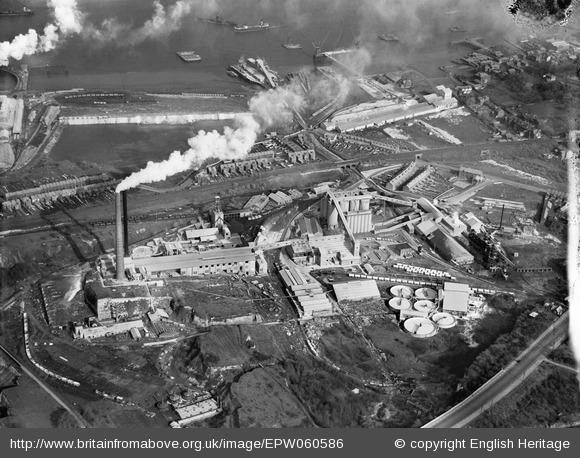
Britain from Above features some of the oldest and most valuable images of the Aerofilms Collection, a unique and important archive of aerial photographs. You can download images, share memories, and add information. By the end of the project in 2014, 95,000 images taken between 1919 and 1953 will be available online.
This was taken in September 1924 and shows the plant from the east. 44 years after the writing of the article, little of the original plant is in use, but much of it is still there, the original kiln bank dominating the centre of the plant. The old finish mill feed hopper tower is also visible. Zoom in on the plant in High Definition.
The following is a transcript of an anonymous article from The Engineer, XCIII, February 7, 1902, pp 130-133, which describes the plant in its most developed form as a chamber kiln plant. It is believed to be out of copyright.
Note on Imperial units of the time: 1 ton = 1.016047 tonnes: 1 ft = 0.304799 m: 1 in = 25.4 mm: 1 h.p. = 0.7457 kW: 145.037 psi = 1 MPa.
From its foundation in 1877, the plant developed in stages until it had 54 chamber kilns. The article describes the plant at this stage early in 1902, before it installed its first rotary kilns.
THE CEMENT WORKS OF I. C. JOHNSON AND CO., LTD., GREENHITHE.
To be successful commercially, a Portland cement works must not only be well managed, but it must be placed in a suitable position (Note B1); and there are a number of considerations which have to be taken into account in this connection. An ideal works would be situated where all the materials necessary to manufacture were on the site or close at hand, and where the finished material was also used on the spot; for under such conditions there would be no expenses connected with carriage. Unfortunately, such a combination of circumstances must remain ideal—at all events, in this country. Here the manufacturer has to put up with what he can get. Generally speaking, he founds his works where, at all events, he can obtain one of the raw materials necessary on the site. If he is fortunate, he gets two. Thus, he may have chalk and clay, but in this case he will not have coal or coke; or he may have coal and clay (Note B2), but in this case he will not have the chalk. In nearly every case he plans his works by the waterside; for the materials he uses—saving, of course, his fuel—are cheap, and will not bear a heavy freight. Moreover, the ability to get rid of the manufactured cement by water carriage is of supreme importance.
The works which we are about to describe—those of I. C. Johnson and Co., Limited, at Greenhithe—possess the great advantages that they have on the site an enormous quantity of easily get-at-able chalk, and an excellent approach to the river Thames. True it is that clay is not obtainable on the spot; but it has only to be brought from a comparatively short distance, the company owning a quantity of clay land on the Medway (Note B3). Having its own wharf on its own premises, the necessary fuel is obtained at minimum expense, while as the wharf is large enough, and has at all times at least 20ft. of water round it, 2000-ton ships can come alongside and either deliver material or take away cement with as little delay as may be. From this works the company's cement is sent away entirely by water. There is no use whatever made of the railway, although it traverses the works (Note B4). It is worthy of note, too, that the water necessary for carrying on the various operations of manufacture is present in ample quantity, and can be obtained with but little cost for pumping, since the water level lies but 3ft. or 4ft. from the surface in some parts of the site. In fact, it may well be said that the position chosen for the works has been selected and laid out with skill and ability.
The works were commenced in 1877. Previously to this time chalk had been shipped from this exact place; indeed, from evidences discovered when the company was constructing its wharf, there is reason to believe that this place was one of the oldest chalk-shipping centres on the river Thames. The land acquired by the company covers some 200 acres, and contains enough chalk to suffice for very many years to come for the requirements, not only of these works, but of those in Gateshead belonging to the same company, and to which, as we shall afterwards show, chalk is continually being sent. The accompanying plan, Fig.1, shows the central portion of the site, that containing the works proper.
It would be impossible to show, within reasonable dimensions, the whole extent of the property. It will be observed that on the plan each building, or group of buildings. is provided with a number. By referring to the numbered table, it may be discovered what each of these buildings is. As will be seen, railway lines are laid throughout the works. There are, in all, some 4½ miles of these, and the gauge is all 3ft. 9in. For taking the trucks over these six steam locomotives are employed. There are also some lighter lines, of much smaller gauge, on which small tip trucks can be wheeled about by hand. Chalk is at present being obtained from several parts of the site. It is taken in the trucks and deposited alongside the line near the wash mills, which are marked 5 on the plan. Close by is also shot the clay brought in trucks from the wharf, where the barges from the Medway are unloaded. The line leading to the wharf is shown on the right hand of the plan. We shall have occasion to allude to the wharf and its appliances later on.
The greatest care is taken with the weighing and proportioning of the chalk and clay as it is put into the wash mill (Note B5). The method of procedure employed is as follows:—The clay and the chalk are loaded separately into hand barrows of known weight. There are two weighbridges. that for the chalk being under the immediate supervision of a foreman weigher, the recording portion of the apparatus being contained in a glass windowed cabin. The clay is weighed on a weighbridge close at hand, and well within sight of the foreman weigher. The amount of clay weighed at each operation is kept constant. The workmen themselves do the weighing of this material, and it is wonderful to observe what excellent guesses they make at the weight, very little adjustment usually being required when the barrow is wheeled on to the bridge. Any variation in the proportions of the ingredients used is made in the amount of chalk. The foreman weigher himself weighs the barrows of this substance, from which, of course, the flints have been removed, and keeps a record, not only of these, but of the barrows of clay as well. He also has a further and most important duty, in that he has charge of the wash mills, and is responsible for the amount of chalk and clay which is put into them in order to obtain any required mixture. He has, in addition, to keep a record of this. His actions are controlled from the chemical department. Continuously during manufacture samples are being taken and analysed. Notice of any alteration to be made in the requisite proportions is at once conveyed from the laboratory to the foreman who makes the change. We are informed that it is no uncommon thing for an addition or subtraction of 1 lb. weight in a total of some 500 lb. to be required. In spite of the somewhat rough and ready method of tilling and emptying hand barrows, with no attempt at scraping out, it appears that even such small differences as 1 in 500 make themselves apparent in the final result (Note B6). It is this attendance to small details which makes for success in the manufacture of cement.
The wash mills employed are of the ordinary type, having revolving spider arms carrying depending stirrers. The mingled slurry finds its way through gratings into catch-pits placed at that side of the wash mills remote from the holes into which the clay and chalk are charged. From these pits the mixture is in each case lifted by means of a revolving bucket wheel, which takes it to such a height that it can flow down wooden shoots leading to horizontal stone mills. These are contained in the building marked 6 on the plan. There are in all six mills, and they are driven by bevel gearing from a shaft running under the floor of the building, which is raised off the ground. This shaft also drives the pump in the building marked 7, which forces the ground slurry as it comes from the mills through flanged pipes to every part of the works where it is required. This pump is a triple ram force pump, with plungers 12in. in diameter, and having a 14in. stroke. The engine for driving these grinders and pump contained in 6 and 7, and also the wash mills, &c., is contained in the building marked 8. It is a horizontal compound engine driving through gearing on to a horizontal shaft. It obtains its steam at 80 lb. pressure from a battery of elephant type boilers contained in the building 11. This engine runs condensing—as, indeed, do the other main engines in the works. The water necessary for this is obtained a few feet below the surface. In the next compartment—numbered 10—is a horizontal engine working by ropes on to a countershaft, from which is driven—also by ropes—a two-pole dynamo. This supplies current for the whole of the works, there being a combination of arc and incandescent lighting (Note B7). This engine obtains its steam from the elephant boilers already mentioned, which also supply steam to an engine driving a grinding mill hereafter to be described.
These works, we are informed, witnessed the birth of the Johnson chamber kiln (Note B8), and there are no less than 54 kilns of this kind, but of different types, in various parts of the works. Some of these are of the ordinary tank form, in which the gases go direct over the top of the slurry, when it is being dried, to the chimney. Of these there are some as much as 120ft. long. In the later designs the slurry is held on a floor of iron plates carried on brick arches. In these the heated gases generated by the combustion of the charge arc first led over the top of the slurry to the end remote from the kiln as in the original form; they then descend by two vertical flues to two horizontal flues running under the iron plates towards the kilns again, these flues being connected to a further horizontal flue running also under the iron plates back to the far end of the chamber and thence to the chimney. Then there are kilns with firing pits, and others—the latest (Note B9)—where these pits are done away with, the fire being carried on removable girders, the level on which the trolleys are taken for the purpose of removing the burnt clinker being the same as the surrounding ground. The various modifications have been carried out with the object of cheapening production and facilitating the removal of the clinker. At the present time there are no rotary kilns or other apparatuses of this kind. It will be observed from the plan that there are three sets of kilns. There is one row containing as many as 33 kilns, and two other rows containing 12 and 9 respectively. Taking them on the average, each kiln will produce 27 tons of clinker per "burn," and three " burns " are obtained from each kiln every 14 days (Note B10). The tanks are, of course, filled with slurry from the flange pipe already mentioned.
When the burning is finished and the charge has cooled, the clinker, after being carefully inspected and the underburnt portions removed. is taken in trolleys running on the narrow-gauge lines already mentioned to either one of the two grinding mills which are on the premises. The first of these—which is contained in the buildings marked 12 and 13—consists of three horizontal stone mills in conjunction with a tube mill. The clinker is first broken in a crusher, and is then elevated by means of a bucket conveyor to the stone mills, the delivery from which descends to a tube mill, which in its turn delivers on to an endless belt. This belt drops the cement into a conveyor which communicates with the various bins in the cement warehouse No. 15. The engine driving these mills and their accessories is contained in building No.14. It is a horizontal cross compound engine of about 300 horse-power, and it works in conjunction with a jet condenser. It obtains its steam from the elephant type boilers already alluded to. The second and more modern grinding mill is contained in compartment 18. Here there are ball mills in place of stone mills, though the finishing is done as in the first instance, by means of tube mills. The arrangements in this mill are very complete. Rope-driving is employed throughout—in fact, rope-driving is largely used in all parts of these works—and any one of the mills can be stopped or started at will, irrespective of the others. For taking the cement in its various stages of manufacture about from place to place, either trough conveyors with worms or endless belts are used. Indeed, we are informed that this company was the first to use belts for this purpose. They act extremely well, and in this particular instance. practically speaking, the cement is never touched by hand from the clinker stage until it is delivered, finished, in the storehouses marked 21. Here the delivery could be made, were it necessary to do it, direct into sacks or casks for despatch. the length of time it is on the belt serving practically to bring the temperature of the recently-ground cement down to that of the atmosphere. All the operations are automatic. If it is necessary to take the material to a higher level this is done by means of encased bucket conveyors, and everything has been done to ensure the even working of all the parts. Here, too, there is a complete dust-collecting plant, the dust being drawn into ducts placed in various positions, and all delivering into a settling room, where the dust collects and falls down shoots on-to a travelling belt at a lower level. The driving engine for this part of the works is contained in compartment No. 19, and obtains its steam from Lancashire boilers, contained in No. 20. The horsepower of the engine is about 225. The total storage available on the premises amounts to some 10,000 tons (Note B11). The storage bins can be subdivided, so that it would be quite possible to have ten 1000-ton lots entirely separated from one another. The weekly output of the works is about 1300 tons on the average.
We have before now described minutely the various operations carried out in cement works. It will not be necessary, therefore, to again do so in the present instance. We may, however, draw attention to the method of raising the coke to the charging level of the kilns. This is primitive, but apparently highly efficient. Scaffold poles of the requisite size are provided in the middle of their length with iron hooks. These hooks fasten into iron eyes built into the brickwork at the side of the kilns. The poles are used for lifting baskets of coke in very much the same way as water is lifted from rivers in Oriental countries. At each end of the pole is fastened a rope. One rope has a hook attached to it, on which can be hung the basket. The other rope may be manipulated by one man, and we are informed that calculations show that this method, crude as it may seem, is cheaper and more expeditious than any mechanical device which might be employed. Certainly, the men were wonderfully expert as we saw them at work, and seemed without effort to manage the basket so that it was landed right into the charging door.
As already intimated, great attention is paid to the chemistry of the manufacture at these works. The chemical laboratory is well appointed and conveniently situated, and here a constant series of experiments is continually going on. Attached to it is a mechanical testing laboratory with all the necessary appliances for efficient testing. We had an opportunity of inspecting both these, and of examining the method of keeping the tests which, as regards the chemical composition, are carried out concurrently with the manufacture of all the cement which is made. The company makes a strong point of testing its cement at long dates. We are informed that the averages of three months' briquettes are:— Neat cement, 1100 lb. per square inch; 3 of sand, 1 of cement, 350 lb. per square inch. This is found most useful for comparison with some of the cements, which test high at seven days, but do not increase at a later date.
(NOTE: 350 psi is equivalent to about 14 MPa in modern EN 196 compressive strength testing.)
Naturally enough, there is a considerable amount of repair and constructive work in connection with a works of this class and size. In all cement works the repairs form a heavy item. The company does its own repairs, and a large part of its constructive work as well. There is a large engineering shop—numbered 28 on the plan—and here, besides the work of repairing, is done the over-hauling of the locomotives and the construction of the trucks used for carrying the chalk, clay, flints, &c. There are three smiths' fires, lathes, shearing, drilling, and screwing machines, &c., besides wood-working machinery. On the works, too, are made the casks in which the cement is sent away; and the sacks, too, are sorted and mended on the spot. These operations are carried out in the buildings marked 24 and 3 respectively. There is also a pattern shop and small brass foundry marked 9 on the plan.
About 300 men are employed on the works as a total. Many of these have been with the company ever since the works were started, and they mostly reside in the immediate neighbourhood. They are provided with a good size dining hall—number 4 on the plan—and they themselves manage the catering arrangements. The scheme works well, and is self-supporting. There is an arrangement by which, if the sales do not exceed the expenditure, each man pays a penny per week. We understand, however, that at the present time this subscription is not needed.
As we have already remarked, one of the necessary adjuncts to the success of a cement works is a cheap and ready outlet for the manufactured material. All the cement made at these works is sent away by boat, and for this purpose a wharf has had to be constructed in the river. This, together with the arrangement of the railway lines on it, are shown in Fig. 2. The wharf is large enough for three steamers and eight barges to be alongside at one time. Here are unloaded the barges from the Medway which bring the clay. Here, too, the steamers which take the chalk to the Gateshead works of the company are loaded up. Colliers which have brought coal to London from the northern port are chartered for this purpose. As the quantity shipped is large, and as it is of the utmost importance that the loading should be carried out as quickly as possible, an ingenious tipping arrangement has been devised. It is the patent of Messrs. Watson and Langston, and is illustrated on page 133. One of these is already at work: the second is being erected. It will be unnecessary to remind our readers of the almost universal use of the old-fashioned ballast wagon worked by horses. Although this method is costly, owing to the excessive wear and tear of rolling stock and horseflesh, it would seem that for dealing with low-priced materials such as chalk, stones, ballast, or sand, very little, if any, advance has been made in the methods used until the production of the present arrangement. The apparatus used by Messrs. Johnsons consists of a projecting framework on the wharf capable of being hoisted up so as to allow of vessels being berthed beneath it, and then of being lowered horizontally over the hold. A glance at the engravings on page 133 will show that the platform is carried by chains, which run over pulleys on a wooden framework down under the floor of the wharf where they are attached to winches. On the projecting framework is pivoted a cradle, which when at rest is in a horizontal position, and upon which the metals on which the wagons run are laid. The line on the wharf leading to the tipper are laid on an incline towards it. The loaded truck, on a small impetus being given to it, will travel on to the cradle by gravity. Its motion is arrested by its wheels coming against bent up rails. There is a sufficient over-hang on the truck to allow it when loaded to tip up the cradle, so that the load is shot downwards into the hold of the vessel. The load having been got rid of, the tendency of the cradle is to revert to the horizontal position, which it does, carrying the truck with it. The slight shock caused by a stop arresting the further motion of the cradle when it has become horizontal is enough to send the truck backwards sufficiently to clear the cradle and to roll on to a return line laid with an incline away from the tipper. The result is that the whole action is practically automatic. The truck runs on to the cradle, gets rid of its load, and runs off again without being touched by hand. A. strong brake, actuated by a lever, is fixed to the apparatus, so that the cradle and truck can be held at any angle. It is quite possible with one of these appliances to deal with three-ton trucks at the rate of one a minute There is no reason whatever, though it is here used only for chalk, flints, &c., why this apparatus should not be equally well employed for coals, ores, &c., where large quantities are required to be shipped quickly.
The wharf is equipped with cranes, &c., for the unloading of barges, &c., and the loading of the steamers with cement. Separate portions of the wharf are devoted to each of these operations, so that they can proceed concurrently. In order that night work array be carried on, there are a number of arc lamps along the wharf, and plug boxes are provided for the attachment of flexible cables lighting portable clusters of lamps which can be hung anywhere—over or in ships' holds and over barges. The same principle is adopted in other parts of the works. Outside the kilns, for example, are further plug boxes, and the leads can be taken right inside the kilns, enabling the charges to be laid or removed equally well by night as by day; for work is carried out continuously night and day— Sundays, of course, excepted (Note B12) — by different shifts. The quarrying of the chalk even is carried out by night, and here also specially designed electric fittings are used with excellent effect.
We must not omit to mention a matter which is proving of considerable pecuniary benefit to the company. On a portion of its site the chalk is overlaid by a rich bed of excellent gravel held in sand and loam (Note B13). This would have had in any case to be removed somehow in order to get at the chalk. As a fact, it is being quarried hydraulically by a subsidiary company, which pays to royalty for the privilege. Water, we have already said, is readily obtainable. The gravel is washed down by this, the process having the advantage, besides removing the material, of separating it from the sand and loam. The washing water is led over depositing beds, where the loam falls down in a slurry. This, when mixed with a certain amount of waste from the chalk pits, was found to be an excellent material for making bricks. A brick factory was therefore added, and bricks are manufactured on the site, kilns for this purpose having been erected. The sand, gravel, and larger stones find a ready market, and, as a fact, some 1000 yards of stones for road repairs are sent out per week to various local authorities in London and the neighbourhood. The method of hydraulically working and washing the gravel and sand is, we understand, the subject of a patent, and is similar to the processes at work in the diamond mines at Kimberley. We may also mention that attached to the works there is a large concrete slab factory The company is certainly to be congratulated, not only upon the design and management of its works, but also upon the enterprise exhibited in developing to the full the various advantages possessed by the site.
A third article (February 1908) describes the plant after they have taken the plunge and installed rotary kilns, and appeared in The Engineer, CV, February 28, 1908, pp 211-213, 220. Having waited for many of their competitors to work through the "teething" errors of the new technology, a fairly substantial rotary plant was installed, although it will be seen that the technology was still at a transitional stage, and a lot more had to be learned. The company, still independent of APCM, had, like the other "independents", expanded considerably.
The article, like the others, is anonymous, but it is pretty certainly the work of Bertram Blount. Blount was a professional consultant, and knew that a combination of double-line-spacing and extreme verbosity could turn a thin offering into a substantial-looking report.
In order to match the order of the text, the figures have been re-arranged, although the numbering is kept.
A NEW ROTARY KILN CEMENT PLANT.
In our issue of February 7th, 1902, we gave a description of the cement works at Greenhithe of I. C. Johnson and Co., Limited. We have recently had an opportunity of seeing in operation a new rotary kiln plant which this firm has now had at work for something under a year. This plant is not intended, at present at all events, to oust the old chamber kilns, for they are now working side by side (Note C1). The output of the original works was, it may be remembered, about 1200 tons a week (Note C2). The new plant will make very nearly an equal amount, and hence the firm's capacity for producing cement has been practically doubled. British firms are frequently being upbraided for their backwardness in adopting new methods, but Messrs. Johnsons certainly cannot be accused of this (Note C3), for not only have they laid down the very latest type of rotary kilns, but they have installed a new power plant, which consists of suction gas engines direct coupled to continuous-current dynamos. The whole forms a most interesting arrangement, and we propose to describe it in the following article.
The efficient use of the rotary kiln requires considerable knowledge and skill, but it may be said that when these are brought to bear the results obtained are certainly equal to, if, indeed, they do not surpass, those which have for long been associated with the chamber and other forms of kilns. The same initial mixture of chalk and clay will, however, not do for both types of kiln. If a certain mixture will produce a good result in one, it is by no means necessarily the case that it will do so in the other (Note C4). Some of the failures which have been experienced with rotaries, if we may for shortness call them so, have been due to the fact that this point has not been sufficiently realised. Mixtures which have for years been used in ordinary chamber kilns have, without alteration, been fed into rotaries, and the two types of kilns have not produced similar results.
Messrs. Johnsons have always been particular as to weighing exactly the proportions of the raw materials put into their wash-mills. They do not believe in rule-of-thumb methods, though we must admit that we have known some wonderfully even results to be obtained in works where rule-of-thumb methods of mixing were in vogue. Messrs. Johnsons prefer to know exactly where they are from the very beginning, and this care in weighing is exercised also in the case of the chalk and clay fed into the new wash mills which have been constructed to prepare the slurry for the rotaries. For the mixture to be absolutely right is one of the great secrets of successful cement manufacture, and another equally important thing when using rotary kilns is that the ingredients must not only be most thoroughly mixed, but they must be must completely disintegrated; there must be no lumps. By "lumps" we mean something which, when a dried pat of slurry is examined, can be detected by the unaided eye. With ordinary kilns this fineness of division is not nearly so important. Bits of chalk the size of a pin's head, or even larger, may find their way into the kilns, and the resulting cement may not be affected in any way. The reason for the difference in the action in the two kind of kilns has not, we believe, been satisfactorily explained, but it has been suggested that possibly the prolonged stay of the materials in the ordinary kilns has something to do with the matter. It is easy to understand that this might very well be so, since the period of burning in an ordinary kiln is about a week, while with rotaries, using the wet process, the time occupied between the throwing of the chalk and clay into the wash mills and the final storing in the bins of the finished cement, is only between three and four hours (Note C5). Having regard to the relative speeds in the two cases, it can well be imagined what a considerable saving of ground space there is for a given output of cement when rotaries are used. This point of saving space becomes more and more important each year, for the specifications of consulting engineers get more and more stringent as time goes on. The finished cement has to be stored, perhaps, in layers not deeper than say, 3ft. 6in.; it must be turned so often, and it must remain for such and such a time under the influence of air before being despatched (Note C6). Hence it has become increasingly necessary for the cement manufacturer, who has to fulfil all these stipulations and many more, to make his cement as cheaply as he can, compatibly, of course, with good quality; and it is undoubtedly cheaper to employ the rotary kiln than the ordinary chamber kiln.
The questions then arise, is the material turned out by rotaries worse than, equal to, or better than cement from ordinary kilns? The reply is that both in appearance and quality it is equal to the best cement which can be produced, providing, of course, that the plant has been properly designed in the first instance, and that it is properly worked. We are informed by Messrs. Johnsons that even experts cannot tell either by tests or by appearance the method by which a given sample of their cement has been manufactured (Note C7). Still, although all this may be
so, it is undoubtedly a plucky thing for any firm, after years of working with one process, to adopt not only another which is entirely different, but, in addition, to make a radical change in the method of driving the machinery. We may here repeat, however, that it does not appear to be Messrs. Johnson's intention to discard, at all events at present, their numerous chamber kilns, but to use them concurrently with their rotaries.
With so much preliminary we may proceed to discuss the actual plant, and to do this it will be convenient to start at the commencement of operations, or, in other words, with the prime movers. We believe that this the first instance of the employment of gas engines with
suction producers for motive power in a cement works in this country. The adoption of this form of power was not made without the most careful inquiries and investigations, The final decision was not uninfluenced by the facts that a mixture of coal and coke can be used in the producers, that, the works being on the banks of the Thames, coke is readily obtained from the large London gas companies at a moderate price, and that coal can be brought to the site by water.
The Power House. Somewhat irritatingly, the right-hand part of the front elevation is actually the side elevation.
We need not go again into the question of the layout of the works, having discussed this in our former article. It will suffice to say that the coal and coke are brought in trucks drawn by steam locomotives from the company's wharf to the rear of the new engine-house. At this point they are shot on to the charging platform of the Dowson gas producers, of which there are four. A glance at the accompanying engraving—Fig. 2—show how these and the mains into which they deliver are arranged. There are in the engine-house—which is a simple brick building with its roof formed by a water tank, and with one end closed in at temporary manner so as to permit of easy future extension—three double-cylinder gas engines made by the National Gas Engine Company. These engines each drive a direct-current compound-wound dynamo made by Messrs. Siemens Brothers. The gas engines are of the horizontal type, each cylinder being governed and fired by magneto from a separate shaft. The engines and dynamos are coupled direct through flexible couplings, and the foundations of all the machines and engines are formed of one solid mass of concrete. We carefully noticed in various positions to see whether there was any vibration, and we found that there was practically none, and the engines which were running at a speed of about 170 revolutions per minute, were working very sweetly and well. We were informed that it was customary to run each engine for a period of fourteen days without stopping night and day, and that this practice had been in operation for some ten months, with no stoppage due to valve or other similar trouble. The rated brake horse-power of the engines is something over 200, and the dynamos are each designed for an ordinary output of 155 kilowatts at 220 volts at 170 to 175 revolutions per minute, though both engines and dynamos are capable of taking heavy overloads for long periods. Two of the engines are always at work, the third being used as a standby. A switch-board is fitted at one end of the engine-room, and is fixed well away from the wall, so that easy access may be had to the back connections. The field windings of the dynamos are connected to equalising switches on the board, and we may say that the dynamos work in parallel perfectly, there being practically no motion of the main voltmeter needle, though very heavy alterations in load may be taking place. The current is conveyed by over-head cables to the various points where it is used, and these will be referred to in due course. Views of the engine house and switchboard are given in Figs. 3 and 4.
Figure 3: inside the Power House, showing No 3 gas engine in the foreground, with the flywheel and dynamo behind.
Figure 4: The switchboard, which is at the far end of the room in Fig. 3.
The next portion of the new plant to be considered is the wash mills. There is nothing special in the design or construction of these. There are four of them placed in juxtaposition and arranged in pairs so that one of each pair feeds the other, and so that the materials get a double treatment by the revolving arms and beaters. Each mill is 18ft. in diameter, and the motor working them and other mills, which we shall mention immediately, is a Siemens machine of 120 horse-power, driving by ropes on to shafting. A special siding and platform have been arranged for the new mills. The chalk obtained from the site, and the clay coming from the company's property on the Medway, are brought to the siding and shot at different ends of the platform. Thence they are taken in hand barrows to the weighing house, where the weight of each barrow load is most carefully taken and recorded. There is one weighing machine for chalk and another for clay. After being weighed the correct number of loads of each substance is shot into one or other of the first two wash mills, into which there is always flowing the regulation quantity of water. After passing through this mill, and getting broken up by the beaters, the mixed materials flow by gravity into the next mill, where they are subjected to further beating.
For the manufacture of cement in ordinary kilns, the resultant slurry would then be taken to horizontal stone mills, but for rotaries a different course is pursued, largely, we believe, because it is necessary to remove all traces of flint, as well as to rid the mixture of the larger particles of chalk. In the present case the slurry is lifted by a bucket wheel from the catch pit into which the second of each pair of wash mills delivers, and is taken into a series of three smaller mills of special construction. Each of these mills consists of a circular tank some 6ft. or so in diameter. Inside this there is a further tank a foot or more less in diameter, so that an annular space is left between it and the outside tank. The slurry raised from the washmill sump is delivered into the inside tank, which is provided with a number of vertical openings some 6in. or so wide, arranged at equal distances round its periphery, and some 2in. or 3in. apart. These openings are covered with sheets of metal gauze, having openings ½ mm diameter (Note C8). Inside the inner tank is a special form of beater, which can stir the slurry up and throw it outwards by centrifugal action against the gauze-covered openings. The result is that a certain portion of the slurry is forced through the gauze and finds its way into the annular space above mentioned. This slurry is then in a condition to be burnt, and is led away by gravity to two reservoir mixers, which will shortly be referred to.
There is a certain amount of residuum left in these mills, and this flows away by gravity to a fourth mill of similar construction, saving that the openings in the gauze are ¾ mm, instead of ½ mm diameter. Here a considerable quantity of water is added, and the matter which finds its way through the gauze is led back to the wash mills to be further broken up, and to be returned in due course to the three smaller mills. What remains inside the fourth mill consists almost entirely of small particles of flint. These are removed, and form at present a waste product.
It will thus be seen that the cycle of operations is continuous, and that an exceedingly fine-grained and well mixed slurry is always being produced. The delivery from the three smaller mills might be taken at once to the kilns, but so as to provide for stoppages on Sundays, when the mills are not worked, though the kilns are, the two reservoir mixers have been constructed. These are placed side by side. They are each 30ft. in diameter, and are provided with revolving stirrers, so as to keep the slurry in proper condition for use (Note C9). When one reservoir is full the slurry overflows from it into the second. From the sump into which these two mixers deliver the slurry is raised by pumps to a platform above the feeding ends of the rotaries, the lift being some 36ft. An interior view of the pump house is given in Fig. 5.
Figure 5: The Pump House, with two sets of 3-throw pumps.
For this purpose two sets of pumps have been installed, one set being sufficiently powerful to deal with the full amount of slurry required, the other set acting as stand-by. Each pump has three vertical rams 8in. in diameter. They were made by Taylor, of Rochester, as also, we may mention, was the mixing arrangement. The pumps are driven through double reduction rope gearing from a 40 horse-power Siemens motor. It is to be noticed that rope driving has been much used throughout the new works, and it appears to be answering extremely well, the absence of noise being particularly noticeable. The slurry is delivered on the kiln-charging platform into a small stirring tank 12ft. in diameter, in which a revolving stirrer is continually at work. Above the end of each kiln there is a wooden measuring tank. These tanks are charged from the mixer just mentioned, and at stated intervals the contents are let down into the kilns by the withdrawal of the plug leading to the pipe A in Fig. 1 (Note C10).
The Rotary Kiln House. Notice that all dimensions, including civils, are in millimetres.
View HD image in a new window.
There are three rotary kilns (Note C11), each being 110ft. long. They are cylindrical in form, and 7ft. in outside diameter (Note C12). They are entirely lined with fire-brick, the thickness of which is, at one end, 9in. They are driven by a 190 horse-power motor (Note C13), which is fixed in a room by itself, so as to protect it from dust and grit as much as possible. This motor drives a rope pulley, and from this ropes are taken to a shaft running across the kiln house. The shaft carries three pulleys for each kiln. Two of these in each case are for giving motion to the kiln, and they are of different diameters, so that a speed of either one or two revolutions per minute may be given to the kiln, depending on which pulley is in use. There are fast and loose pulleys on the gearing, so that either belt can be used at will. There are three reductions between the driving pulley and the kiln, the first reduction being by bevel gearing. The third pulley mentioned as being on the cross shaft is for revolving the clinker cooler, reference to which will shortly be made.
It will be remembered that the slurry is discharged from the measuring tanks through the pipe marked A at the higher end of the kiln. In its passage to the lower end of the kiln the slurry is first of all dried and disintegrated, and is then burnt. The firing is done from the end remote from that into which the wet slurry is discharged, and hence the temperature gradually rises as the lower end is reached, the maximum temperature being in the burning zone, which occupies the space between about 6ft. and 20ft. from the lower end. In this space the temperature rises to something like 3000 deg. Fah., while the gases escaping to the chimney only have a temperature of some 536 deg. Fah.
The kilns are revolved by means of toothed wheels arranged approximately at the centre of their length. These toothed wheels are not connected directly to the shells of the kilns, but by means of tangential brackets, the object being to allow for expansion, and so to prevent the rupture of the toothed rings. The weight of each kiln is taken on three sets of rollers arranged as shown in the engraving—Fig. 1. Rings for bearing on these rollers are loosely held in position round the kiln by means of a series of brackets on each side of the rings. The latter are a very loose fit on the bodies of the kilns, and there is no fear in this case of breakage by reason of expansion, as there is with the driving ring. As a matter of fact, there has been no trouble with breakage of these driving rings, the precaution against damage by expansion, as above mentioned, having proved perfectly efficacious.
The slurry by the time it reaches the lower end of the kiln has been burnt to clinker, and we may say, that we carefully examined a good deal of it, not only as it came from the kilns, but by observing a large heap of it and found that it was exceedingly well and regularly burnt.
The kilns are fired with powdered coal, which is reduced to such a state of fineness that there is not more than 10 per cent. residue on a sieve of 32,400 openings to the square inch (Note C14). The process of grinding the coal requires considerable care and attention, one of the chief points to be observed being that it must be thoroughly dried before the actual grinding process takes place. Before going on to describe the method of drying employed it will be necessary to say a word or two concerning the way in which the clinker coming from the kilns is cooled, because it is the heat extracted from the clinker which is used in drying the coal. The cooler consists of two cylinders, B and C—Fig. 1—which are of different diameters. The smaller cylinder B, as may be seen in the engraving, does not go quite to the end of C, and one end of C is closed. The clinker as it gradually comes away from the kiln by the revolving action of the latter falls down a shoot D into the right-hand end of the cylinder B. The clinker is, of course, very hot, and the method of cooling it employed is the drawing of large volumes of cold air over it as it travels, by means of the rotating motion of B and C, first to the left-hand end of B, and then back again to right-hand end of C. The fan employed for this purpose is mounted above the firing platform of the kilns, and is indicated by the letter P on the drawings (Note C15). It has another function in addition to that already detailed, and to this we refer later on. The air, heated by its passage, as shown by the arrows, over the glowing cement clinker, passes first of all into a chamber E. In this chamber much of the fine dust, brought over with the rush of the air, is deposited. There are two possible exits from chamber E; one is by the trunk F, which connects with the chamber H, and the other through the duct G, which is connected directly to the suction of the fan P. The latter is only used when for any reason it is desired not to use the chamber H. In the latter there is a revolving drier I. Into this the coal, after passing through a crusher, is deposited by means of arrangements which are not shown on the drawing. As the coal passes from end to end of this drier it is, of course, subjected to a high temperature by reason of the heated air in the chamber. The result is that it is completely dried. In this condition it falls into a hopper and is raised by the elevator LL and deposited into the hopper J. The delivery from this is into a Kominor grinding mill and thence into the tube mill K, in which the coal is ground to the requisite fineness, and in this condition it falls into a hopper and is lifted by the elevator L1L1 to such a height that it can fall by gravity into the hopper N, from which the supply for firing the kiln is drawn. The firing is brought about by forcing into the end of the kiln R a mixture of hot air and powdered coal. The hot air is driven into the kiln through a pipe Q by the fan P, and obtains its heat from the clinker; as already explained. The coal is fed by a worm-feeding apparatus into the pipe O, which is in communication with the discharge pipe of a smaller fan S. The result is that a continuous stream of finely powdered coal, together with a large volume of heated air, is forced into the kiln R through the nozzle Q1. The amounts of coal and air can be regulated to a nicety, the former by altering the position of a friction wheel on the friction disc driving the worm-feeding mechanism. The man in charge of the burning can tell by observing with blue glasses through peep holes in the ends of the kilns exactly how the combustion of the coal is going on, and how the burning is proceeding, and he can make his adjustments accordingly. The coolers are, as we have said, revolved by belts from pulleys on the main shaft, which also drives the kilns themselves.
It should be said that each kiln is kept entirely separate from the others, not only as regards its feeding and burning arrangements, but also as regards its chimneys. Messrs. Johnsons have gone to the expense of building a separate chimney for each kiln, being fully persuaded that only in this way can the draught be correctly regulated and the best results obtained. It may be mentioned that there is also a separate dust chamber at the base of each chimney, with doors for the ready removal of the considerable quantities of dust which collect (Note C16). Our readers will have no difficulty in seeing from the engraving how all the various parts we have mentioned are driven. In every case the motion is obtained by means of electric motors. The whole of the rotary kiln plant was supplied by Messrs. F. L. Smidth and Co., of Copenhagen, Messrs. Johnsons being unable, at the time the plant was put down, to obtain what they required in this country (Note C17). It must be said that the work throughout has been carried out in excellent fashion. Views of the kilns from the firing and charging ends are given in Figs. 7 and 8, on page 220.
Figure 7: east-facing view of the kiln house from the firing floor.
Figure 8: a higher-definition version of this from the Blue Circle Archive. West-facing view from the cold end of the kilns.
In our description the point has been reached in the process of manufacture when finished clinker is being produced in a regular stream, It now remains to grind and to store it. As the clinker comes away from the coolers it drops upon a horizontal plate conveyor running across the kiln-house. On its way it passes over a Denison automatic weighing machine—Fig. 9—which records the amount of material carried on the conveyor. So accurately is this weighing carried out that the records are taken as a basis for paying the men, who accept them readily (Note C18).
Figure 9: a view of the clinker conveyor carrying all three kilns' product, with a Denison weigher left foreground. The conveyor ran between the first and second piers, and No 3 concentric rotary cooler can be seen above, with the hot end towards the left.
The conveyor delivers the weighed clinker into a hopper, from which it is raised by the aid of an elevator to another conveyor. The latter, which is also of the plate type, takes it to the grinding plant, which is in a neighbouring building. An illustration of this plant is given in Fig. 10, and in referring to it we may call attention to the conveyor staging, which is visible outside the building The clinker descends first of all into a ball tube mill 6ft. 2in. in diameter, and from it to a flint mill of the same size. The former is charged with steel balls varying in size from 4in. to 2in. in diameter. The size of the flint balls in the second mill is from 2in. to 1in. in diameter. From the latter the cement is discharged in a finished condition, and is led away by band conveyors to the bins in the store-house, at one end of which the grinding mills are situated. The grinding tube mills were supplied by Messrs. E. Newell, of Misterton, Gainsborough. The motor driving them is of 260 horse-power. A view of it is given in Fig. 6, which may be taken as typical of all the motors employed, and we may add that there are six of them, aggregating in all some 650 horse-power employed throughout the works (Note C19).
Figure 10: the new ball- and tube-mill set for finish grinding. This, I think, is an eastward view, and the overhead clinker conveyor from the kiln house can be seen through the door.
Figure 6: A 260 HP (194 kW) finish mill motor.
The whole of the plant has been exceedingly well laid out and erected. It has now been in full operation with only one break of four days during the last Christmas holidays for some ten months. There has never been any other entire stoppage. When in full operation, as we saw it, the plant produces some 1000 to 1100 tons of cement per week.
The various engravings which we are enabled, by the courtesy of Messrs. Johnsons, to reproduce, give a good idea of the new installation, and will not require any further reference than that which has been already made.
We may add that since our last article on these works a large cooperage has been put to work. The firm does a large export trade, and a large quantity of the whole amount of cement shipped is sent away in wooden casks. A complete equipment for making these casks has been laid down. There are machines for cutting, shaping, and grooving, and tongueing the staves; for forcing the hoops on to them, and for making and putting in place the end pieces. The result appears to be the production of wonderfully serviceable casks, which are made all the stronger by the fact that the hoops are fashioned from band steel specially corrugated on the spot. This corrugation, of course, makes the bands very much stiffer than they would otherwise be, so that the casks are all the better able to withstand rough usage.
A special feature of these casks is that the staves from which they are made, before being shaped, grooved, and tongued, are thoroughly dried by being passed through a chamber heated by hot air to a temperature of 180 deg. Fah., the transit through the chamber occupying six days. This thorough drying of the wood has been adopted to minimise the possibility of any subsequent shrinkage after the casks are made and to render them particularly suitable for exportation to hot climates.
It may be of interest if we give the following particulars regarding the cost of power in the new plant. We are informed by Messrs. Johnsons that during a continuous six months' run the total production of electrical energy was 672,159 Board of Trade units, this figure being obtained from watt-hour meters in the engine-room. Including all stand-bys, loss, and stoppages, the total fuel used was 2.056lb. per unit, the cost being 0.255d. per unit. The fuel used was a mixture of Welsh anthracite coal and gas coke (Note C20).
Following the satisfactory performance of rotary kilns 1-3 described above, Johnsons embarked upon a fourth, larger rotary kiln. Kiln 4 was installed after the BPCM takeover, and started up in 1913. It did not necessarily represent an increase in capacity - but the 170 t/day kiln at a stroke more than equalled the 50,000 t/year capacity of the decrepit 40-kiln plant at Gateshead, and marked the final transfer of Johnson's production to the Thames.
Kiln 4 was one of a number of more-or-less identical design installed around that time by Newells (the others being British Standard 1, Burham 1-3 and Cliffe 1). I have found no explicit description of the kiln. However, a series of articles was published in Cement and Cement Manufacture in 1930, describing the technical assessment of a "typical" wet process kiln. The kiln described is clearly Johnsons Kiln 4.
The articles are by William Gilbert (1867-1938) and are believed to be out of copyright. They appeared in Volume 3, 1930 (Part I Jan pp 41-54: Part II Mar pp 419-429: Part III Apr pp 561-566: Part IV May pp 699-704: Part V July pp 946-953: Part VI Sep pp 1196-1206: Part VII Nov pp 1472-1484). Many more articles by Gilbert appeared, devoted to ancillary equipment and to the processes of heat transfer. Gilbert was a consultant, and designed the Southam rotary kiln plant for Kaye & Co., in collaboration with David Butler. They were taken on to operate the A/BPCM research programmes in 1913 - the incipient Blue Circle Group rightly believed that if large organisations have any virtue at all, it is their ability to make use of a critical mass of big data not available to small operators. These activities continued with expanded scope when the Government-sponsored British Portland Cement Research Association was formed in 1918. The articles discussed here describe test work done under the auspices of the latter organisation between 1918 and 1925. Numerous operating kilns were examined in great detail. 29 "kiln tests" such as this had been completed by A/BPCM then by BPCRA between 1914 and 1921, and the Johnsons kiln was presumably selected as a published example because it represented a more professional and modern operation than many of the others. The test probably took place in July 1919. The articles describe many of the features - established nearly a century ago - of a process engineering assessment of operating plant still practiced today with only minor advances in sophistication.
Part I discussed the general salient features of kiln system design. Part II discussed measurement methods used. In Part III, the example kiln system is described.
The Rotary Kiln in Cement Manufacture - III
DESCRIPTION OF A ROTARY KILN TEST
Figure 17: Key Plan of Works
Figure 4: Twin Screw Coal Feeder
Figures 18 & 19: Cooler Chute Arrangement
Figure 3: Rotary Slurry Feed
It is now proposed to describe in detail a test for six days of a typical wet-process rotary kiln. A general plan of the plant is shown in Fig. 17. The coal store is a plain shed with a concrete floor. The coal is delivered in railway wagons, the rail level being about 10 ft. above the coal store floor. In ordinary working the coal is not weighed; it is wheeled in barrows to the 9 in. by 24 in. crushing rolls. There is no feed gear. The rolls are set about 1¼ in. apart, and serve to break up the larger lumps. The coal is elevated and delivered directly to the drier without any intervening hopper or feeder. The coal drier is 5 ft. diameter and 50 ft. long. It is heated by a separate furnace.
From the drier the coal is elevated to a hopper of 1 ton capacity over the ball mill. Each tube will is provided with a small hopper of 250 lbs. capacity only, and an arrangement is provided to pass the ball mill delivery to any two of the mills.
Leaving the tube mills, the fine coal is elevated to a powdered-coal hopper 12 ft. 6 in. in diameter and holding 20 tons.
The coal is delivered from the hopper by a feed gear similar to that shown in Fig. 4. The screws are each 4¾ in. diameter by 2 in. pitch (Note D1), and the speed variation is from 100 to 150 r.p.m. (Note D2)
Rotary Kiln.-The kiln is 8 ft. 6 in. in diameter and 202 ft. long, with a clinkering zone 10 ft. in diameter and 40 ft. long (Note D3). The firebrick lining is 8 in. thick in the clinkering zone, followed by 55 ft. of lining 6 in. thick and 92 ft. of lining 4½ in. thick. The volume inside the lining is 9,354 cubic feet (Note D4).
The kiln has two speeds obtained by two sets of fast and loose pulleys; fast speed 0.95 r.p.m.; slow speed 0.76 r.p.m. (Note D5) The slope of the kiln is 1 in 25.
There are no slurry lifters, but there are 150 cast-iron brackets in the last 95 ft. of the kiln. The brackets are 3 in. wide and project 12 in. from the face of the firebrick. The total exposed surface is only 75 square feet (Note D6).
Rotary Cooler.-The cooler is generally 5 ft. 6 in. diameter inside the shell plates, and 67 ft. long over all. There is an enlarged end 7 ft. in diameter and 8 ft. long. Slope of cooler, 1 in 16.7. R.p.m. of cooler, 3.16. The internal arrangements of the cooler will be further described when dealing with the cooler-shell radiation. Owing to the configuration of the ground the cooler is placed at right-angles to the kiln (Note D7).
Clinker Chute.-The connection between the cooler and kiln is shown in Figs. 18 and 19. There is a gap between the cooler end and the face of the wall through which a certain amount of cold air enters the kiln, and 3 to 4 per cent. of the hot clinker is spilled out on to the ground. Originally there was a cast-iron clinker chute lined with firebrick, but this was removed and the arrangement shown on Figs. 18 and 19 substituted. The minimum area of the clinker chute, in cross section, is 9 sq. ft.
Slurry Feed.—A rotary feeder is provided similar to that shown in Fig. 3. The extended shaft of the feeder projects over the end of the kiln, and it is driven by a belt from the kiln shell. The kiln-burner increases the feed at times by putting a block of wood in the overflow pipe.
Coal Firing Nozzle.—This is a plain pipe of 6 in. bore, projecting 16 in. into the end of the kiln.
Horse Power Required.—The average horse power used is: kiln, 33.0; cooler, 8.0; coal-firing fan, 4.0.
Kiln Flues and Chimney.—Leaving the kiln, the waste gases pass through a dust chamber of 4,700 cu. ft. capacity, which intercepts about 0.45 tons in 24 hours. The chimney is approximately 300 ft. high (Note D8).
Kiln Test Sheet
Referring to the Kiln Test Sheet, it will be seen that the period was six days only, the figures being made up to 12 noon on each day.
The coal was weighed from the store in barrows, over a platform weighing machine in 2½ cwt. lots, and then tipped to the coal rolls.
Previous to starting the test, the coal drier was run without feed for 1 hour, the ball mill hopper was run empty and scraped out, and the ball mill and tube mills were stopped on full feed immediately the hopper was empty. The upper surface of the coal in the large fine-coal hopper was levelled, and the depth from the top measured at 12 noon when the test started. At the end of the test all the conditions were observed again, so that the only correction to be made to the amount of coal weighed was that for the difference in level in the fine-coal hopper at the beginning and at the end of the test.
Referring again to the test sheet, the actual running time of the kiln in row 2 is obtained in the first instance from the burner. The burner on each 8-hour shift records the time the kiln is stopped and the reason for the stoppage. A speed recorder was driven from one of the shafts of the kiln driving gear, and, the kiln stoppages being recorded on the chart, a check on the kiln running time is thus obtained.
A sample chart is shown in Fig. 20. It shows clearly when the kiln was on the fast speed and when on the slow speed, also the duration of the stops. It will be noticed that after each stop the kiln was placed on the slow speed (but with full coal feed) for a short period in order to warm up. The kiln stops shown every three hours (marked B on chart) were made for the purpose of obtaining the actual delivery of the coal-feed screws per 100 revolutions. For this purpose a by-pass arrangement with deflecting valve was fitted, so that the coal leaving the feed screws could be delivered into a bag for about one minute and then weighed (Note D9). The number of revolutions made by the coal-feed screws was recorded by a counter throughout the test.
Figure 20: Kiln Speed Chart 16-17/7/1919
In this manner a figure was obtained for the average weight of fine coal discharged per 100 revolutions of the feed screws. This figure multiplied by the total number of revolutions made should give the weight of dry coal entering the kiln. Making suitable corrections, there was close agreement on this particular test between the weight of coal so estimated and the weight of raw coal used as obtained by weighing. Such close agreement, however, was not always obtained.
The periods for which the kiln was on slow speed, independently of those due to the coal by-pass arrangement, are marked H on the chart. They are relatively few in number, and would probably have been less but for the disturbance to the working of the kiln caused by the coal by-pass stoppages.
The general conclusions drawn from the chart are that the kiln speeds were suitable for the slurry feed used, and that the coal feed and the slurry feed were both uniform in working.
At some plants a similar chart showed that the kiln speed was changed two or three times per hour, thus indicating an irregularity in working which had to be traced.
row 3.-A revolution counter was driven from a shaft of the kiln-driving gear, the ratio of the r.p.m. of the shaft to that of the kiln being known. The counter was read at 12 noon daily, and from the total number of the) kiln revolutions in 24 hours and the actual running time the average r.p.m. of the kiln were obtained.
The slurry data, as recorded in rows 4, 5 and 6, is obtained by the chemical staff at the works as part of their routine, which goes on whether a kiln is being tested or not (Note D10). The method of obtaining the data in rows 7 to 12 has already been described (Note D11).
Figure 8: Rotary clinker weigher
On the contents of a quadrant reaching the correct weight the drum sinks; this movement clears the stops G from the stop pieces F, and the drum, being out of balance, rotates, discharging the weighed clinker. As soon as the clinker commences to leave the quadrant the weights on lever C restore the drum to its original level, and the automatic stop mechanism prevents the drum from rotating more than one-quarter of a revolution. The drum is retained in position during filling by the spring-controlled lever H.
The machine had to be calibrated. Various accounts show that the weight per quadrant had a standard deviation of around 3-4% of mean.
row 13.-The clinker leaving the cooler fell into a rotary weigher of the type indicated in Fig. 8.
The delivery from each compartment was checked several times daily on a platform weighing machine, and was found to range from 64.2 to 66.9 lbs. Leaving the rotary weigher the clinker was elevated, and it was found convenient to deliver it into trucks of 24 in. gauge. It was then re-weighed over a platform weighbridge, the total weight for the six days being thus obtained. An average delivery of 65.3 lbs. per compartment was deduced for the rotary weigher.
rows 14, 15 and 16.-The waste-gas analysis was made by an Orsat apparatus at regular intervals throughout the day (Note D12).
rows 17, 18 and 19.-The temperature of the clinker leaving the cooler was obtained by catching the discharge in a wooden box of 6 in. cube and inserting a mercury thermometer. Considerable care is necessary, otherwise the reading obtained is too low (Note D13). The kiln-exit gas temperature was taken on a single-thread recorder.
The temperature at the chimney base was observed at regular intervals by a pyrometer and portable indicator, and the readings averaged for a daily result. In this case the connecting flue between the kiln and chimney is of exceptional length, viz., 95 yards, and the fall of temperature between the kiln exit end and the chimney base, due mainly to the inleakage of cold air, will be noted (Note D14).
The Rotary Kiln in Cement Manufacture - IV
The rest of the article goes into the minutiae of measurement techniques, which are discussed elsewhere. Here, I just transcribe the main conclusions.
Coal and Clinker Measurements.
Referring to Row 7 on the Test Sheet, it will be seen that the raw coal weighed out during the test was 282.8 tons. It is convenient for calculation purposes to express all coal quantities as "reckoned dry"; in this case the conversion is made as follows (Note D15):—
Tons
Raw coal weighed out during test
282.80
Deduct moisture, 1.85%
5.20
Coal weighed, reckoned dry
277.60
Contra Account.—To be deducted there is a loss of 5.58 tons of coal from the drier as volatile matter and dust (Note D16), an allowance of 2.35 tons for a higher level in the fine-coal hopper at the end of the test, and an estimated allowance of 5.87 tons for warming up the kiln every three hours after the stops to take the coal by-pass readings. All these quantities are reckoned dry, and their total is 13.80 tons; hence the correct figure to take for the weight of dry coal used by the kiln is (277.60 - 13.80) = 263.80 tons.
Clinker Made.—The total clinker weighed out, including the spill at the cooler end, was 928.9 tons. The actual running time from Row 2 was 133.3 hours, hence the clinker output per hour = 928.9/133.3 = 6.97 tons.
Standard Coal Consumption of Kiln.—From Row 12 the average calorific value of the coal used was 13,513 B.T.U.'s per pound (Note D17), hence—
Standard Coal, per cent. on clinker = (263.8×13513)/(928.9×12600) = 30.47 (Note D18)
Draught Measurements.
The averages of the readings taken every three hours throughout the test are:—
The observations in lines 4, 9, 11 and 12 were taken every three hours, that in line 10 by a thread recorder, and the remaining observations were made during the day as opportunity occurred.
The temperature of the air entering the kiln hood from the cooler, line 5, was measured by the hot-air pyrometer previously described (Note D20). Three oval pipes, 3½ in. by 2½ in. inside, were built into the front of the kiln hood near the base (see Fig. 18) , and these openings were used both for the air temperature measurements and for the quantity of air entering the base of the kiln hood from the clinker chute. The small gap between the base of the kiln hood and the firing platform was cemented up.
The figures in lines 6 and 7 were taken by an optical pyrometer and are assumed to be correct (Note D21), but for line 8 the temperature of the clinker leaving the kiln, owing to the more exposed situation, the optical pyrometer apparently read about 185 deg. F. too low (Note D22). The latter correction was determined by a water calorimeter, using a value for the specific heat of clinker of 0.25. It is, however, rather difficult to obtain the correct temperature of the clinker leaving the kiln under working conditions by a water calorimeter, and several attempts were made before results considered to be approximately accurate were obtained (Note D23).
The calorimeter consisted essentially of an inner copper vessel containing water and an outer sheet-iron vessel, with about ¾ in. air space between. The outer vessel was covered with a thick layer of asbestos sheeting banded on. There were two lids, and a central tube leading down into the inner vessel. The calorimeter, secured to the end of an iron pipe, was inserted through the front door of the kiln hood and a few lumps from the outside of the stream of clinker leaving the kiln were caught in it. It was not always possible to secure a suitable quantity. The calorimeter was quickly withdrawn, and the inner vessel rapidly transferred to a duplicate outer vessel which had not been heated by insertion into the kiln hood. The temperature rise of the water was noted and the dry weight of the clinker afterwards obtained. The mean specific heat of the clinker over the range 2,200 deg.-60 deg. Fahr. was taken at 0.25 (Note D24).
It was found necessary to weigh the water in the inner vessel both before and after the experiment, since the white-hot clinker coming into contact with the water produced a certain amount of steam (usually from 1 to 11 per cent. of the water used) which escaped. The latent heat of this quantity of steam had to be allowed for.
Usually all the other items which are concerned in the cooler heat balance are more easily measured, and from these figures the temperature of the clinker leaving the kiln can be calculated to some definite value of the specific heat.
The article went on to discuss Pitot surveys for the measurement of gas flows. The Pitot technique had existed since 1732, but only came to be used for gas flows when it was adopted for airspeed measurement in aircraft. The BPCRA took it up after the NPL had established designs and operating procedures. William Gilbert became the company expert on the technique. Only the results are given here. The primary air and secondary air flows were measured by Pitot tube: the air entering the cooler was measured by vane anemometer: the inleak at the cooler seal was calculated by difference: the inleak at the kiln seal was estimated from the hood suction. I have corrected the errors, due, presumably, to sliderule calculation.
Area ft2 (m2)
Temp °F (°C)
Mass flow lb/min (kg/s)
Firing pipe
0.196 (0.0182)
83 (28)
64 (0.49)
Entering kiln hood
18.2 (1.69)
569 (298)
872 (6.59)
Entering cooler
23.8 (2.21)
72 (22)
750 (5.67)
Cooler seal inleak
122 (0.92)
Kiln seal inleak
0.53 (0.05)
70 (21)
64 (0.49)
Total entering kiln
1000 (7.56)
The above total may be accepted for the present, and later it will be compared with another estimation made from the weight of coal burned per minute and the coal and waste-gas analyses (Note D25). Subsequent sections went on to develop the kiln and cooler heat balances. The import of these is not specific to Johnsons, but they are great fun, and will be dissected in a separate page.
The fifth article is from Cement and Cement Manufacture (2, 1929, pp 97-107, 161-170) which in 1929 was in its second year of publication, and had already emerged as a platform for publicising the new developments in the industry, and particularly those of Blue Circle. It describes the plant after it had been expanded to what was essentially its final form.The new kilns 6 and 7 had been installed the previous year, and were Britain's largest kilns, remaining so until overtaken by West Thurrock No 6 in 1934. The general uprate of the plant accompanying the new kilns gave an opportunity to demonstrate what was considered the state-of-art design features of the time. Because Johnsons underwent only minor modifications in the remaining 42 years of its life, this is a description of its more-or-less final form, as one of Blue Circle's five large base-load Thames-side plants, each of which made about half a million tonnes a year.
The article is anonymous and is believed to be out of copyright.
Johnson's Cement Works, Greenhithe.
ENLARGED TO 400,000 TONS A YEAR.
The Johnson's Works of The British Portland Cement Manufacturers, Ltd., situated on the southern bank of the Thames at Greenhithe in Kent, are now approaching the completion of an extensive reconstruction and enlargement. The reconstructed works will have an annual output of about 400,000 tons of cement (Note E1).
The chalk quarry adjoins the works. Clay is obtained from two sources, one a London clay deposit two and a half miles distant, where the clay will be washed and pumped to the works; and the other from land near the works.
Chalk Quarry.
The output of chalk required is 120 tons per hour throughout a working week of 140 hours. This material will be handled by an electrically-driven navvy. This machine, which weighs 92 tons, travels on a caterpillar track and has a bucket capacity of 3½ cubic yards. It is connected by means of a trailing cable to a substation of the outdoor type, at which the electricity is transformed from 3,000 to 500 volts.
The quarry face, which is about 100 ft. to water level, is at present being worked in 30/35-ft. stages. The overburden is stripped by means of an oil-driven navvy. The top stage is operated by a steam navvy, and the development of the second stage by a similar machine. The chalk is dumped into 10-ton railway trucks, and hauled in rakes of twelve trucks to the washmill by steam locomotives.
Washmill.
The loaded trucks after arrival from the quarry gravitate down an inclined siding into a side discharge wagon tippler. The chalk is tipped into a hopper, from which, by means of a two-way valve plate, it is fed into either of two wash-mills. These two mills are of standard design, being 30 ft. in diameter. Each mill is driven by a 225-h.p. motor geared through a single-reduction totally-enclosed gear to the Countershaft. For cleaning out purposes the mill is driven by the same motor through a liquid starting resistance, by means of which the mill can be "inched" round as required. Each motor and control gear is housed so that the operator has a clear view of the interior of the mill at all times.
The slurry gravitates from each washmill to three central discharge elevators, delivering through a feed-trough to eight vibrating screens. The screened slurry passes through into a distributing trough fitted with weir-type control outlets which feed it into four 6 ft. diameter by 30 ft. long peripheral discharge wet tubemills. Each tubemill is driven by a 350-h.p. motor through a set of double reduction gears. These gears are totally enclosed and run in oil. The final drive is by a cardan shaft fitted at each end with flexible couplings connecting to the trunnion end of the mill. Each mill motor, as with all motors of 100-h.p. and over, is fed by 3,000-volt A.C. current, the control gear comprising iron-clad draw-out type trucks.
The rejects from the vibrating screens are conveyed by a reversible belt-conveyor into either of two 20 ft. diameter grit mills on the first floor of the washmill, the fine slurry from these mills gravitating back to the washmills and the flint grit concentrates discharging direct into 10-ton trucks below. Each grit mill is driven by a 30-h.p. motor through an enclosed-worm reduction gear to the countershaft. All elevators and conveyor drives in the mill are driven through similar D.B.S. worm gears direct-coupled to the motors.
The flints from the washmills discharge into a flint excavator situated between the two mills, and discharge through a hopper on the grit-mill floor into the grit-trucks below. The flint wash-water is handled by a two-throw drainage pump situated on the washmill discharge level. The fine slurry leaving the tubemills flows to three slurry elevators of the same type and capacity as the coarse slurry elevators, and the discharge flows through a launder to a distributing box situated centrally between four slurry mixers. These air-agitated reinforced concrete slurry mixers are 66 ft. in diameter by 11 ft. 4 in. high, the capacity of each mixed being about 600 clinker tons (Note E2).
All four mixers are interconnected by valves and pipes for equalising purposes, and a second set of suction and delivery pipes connected to one of the pumps in the pump house serves for conditioning purposes.
Clay Supply.
At the London clay deposit the clay is dug by a steam shovel, deposited into trucks, and hauled by steam locos to a washing plant. The clay slurry is pumped by electrically-driven pumps through a 6-in. diameter main feeding into 66 ft. diameter slurry mixers with "sun-and-planet" stirring gear.
The clay deposit on the land adjoining the works (Note E3) is being excavated by means of a floating dredger. An electrically-driven grab at the forward end deposits the clay into a clay hopper which feeds into a washmill at the rear end of the dredger, and the clay slurry from the screens flows into a sump in the centre. From this sump it is pumped by a centrifugal pump through a 7-in. diameter floating delivery main to a 20-ft. diameter storage tank on the shore. From this tank the slurry gravitates to one of two slurry pumps in an adjoining pump house. The power for these two electrically-driven pumps and also for the floating dredger is brought by underground cables to an outdoor-type transformer, in which it is stepped down from 3,000 volts to 500 volts, the supply to the dredger being carried by means of floating cables.
The clay slurry is pumped through a 6-in. diameter pipe-line back to a 66-ft. diameter "sun-and-planet" mixer, two mixers acting as storage supplies for the two clay slurries.
Adjoining these two storage supplies is a 48-ft. diameter air-agitated clay mixing tank, into which clay slurry from the two storage tanks is led and mixed to form a constantly regulated mixture. These two slurries gravitate from each of their respective storage tanks through regulating valves into an existing sump equipped with a bucket-wheel elevator, the mixed slurry flowing from the elevator delivery through a trough into the 48-ft. air mixer.
The mixed clay slurry then flows into a small pump house, in which are situated four electrically-driven slurry pumps which pump into delivery mains delivering clay slurry to a measuring tank at the washmill. This tank, situated above the grit-mill floor, holds an adjustable supply of clay slurry. Part of this clay supply leads direct to the grit mills and the remainder to the washmills, the operation of the tank being controlled by the man who works the chalk tippler.
Pump House.
The slurry from the four 66 ft. air-agitated storage mixers is led by control valves and a 15-in. diameter suction pipe into the main pump house nearby. This building, which was formerly one of the cement warehouses and is 120 ft. long by 92 ft. wide, is divided into three equal bays. The northern bay, which contains band and circular saws, slotting machine, and other tools, is the wagon repair shop. The central bay is the main pump house, and is equipped with six sets of slurry pumps. All the slurry pumps — thirteen in number — in use on the plant are of the one design, three-throw plungers, 12-in. diameter and 15-in. stroke. Each of these six pumps is connected by stop valves to the one 15-in. diameter suction main, and each delivers, again by means of suitable stop valves, to delivery mains, 8-in. diameter, carried on an overhead gantry leading the slurry to the four kilns.
These six pumps, which extend down the centre line of the building and over which runs a 7½-ton travelling crane, are driven through an overhead countershaft at the side of the bay by independent belts, the countershaft being driven by a 150-h.p. motor in the centre of the southern bay. This bay is divided into three sections; one is a storeroom; the centre section is the motor house; the end section contains another motor-driven slurry pump connected by a common suction and delivery main to the four 66-ft. slurry mixers, and is used for transferring slurry from any one mixer to any other for conditioning purposes (Note E4).
Rotary Kilns.
The completed plant will consist of four rotary kilns (Note E5); two existing kilns, called respectively No. 4 and No. 5, each 202 ft. long, 9 ft. diameter, with an enlarged burning zone 10-ft. diameter, will give a combined output of 2,700 tons of clinker per week. Each kiln is provided with a rotary cooler set at right angles to the axis of the kiln (Note E6). The kilns are driven through the ordinary gearing and belt drive by totally-enclosed A.C. commutator motors (65/22 h.p.), having a speed variation ratio 700/230 r.p.m., 3-phase, 500 volts, 50 cycles. The two new kilns, No. 6 and No. 7, are each 317 ft. long overall with a burning zone 46 ft. and 12 ft. diameter.
The clinker coolers are of the recuperator type; twelve cylinders, each 4 ft diameter and 20 ft. long, are placed round the discharge end of the kiln, the centre line of the cylinders lying parallel to the centre line of the kiln. The hot clinker leaves the kiln shell at the extreme end, discharging into twelve holes on its periphery and thus entering into each of the twelve cooler cylinders. In each of these, through the medium of spiral guides, the clinker is slowly transferred to the discharge end where it falls on to a shaker conveyor (Note E7). These kilns are supported on six roller bedplates and are driven through four sets of reduction gears. The first and second reduction gears are totally-enclosed and run in oil under a system of forced lubrication to the bearings and sprayed on the teeth. The motors for these drives are of the variable-speed commutator type of 160/47 h.p., 650/225 r.p.m., 500 volts, 3-phase, 50 cycles, totally enclosed and water-cooled. The revolutions of the kiln can be varied from a maximum of 1 in 70 seconds to a minimum of 1 in 210 seconds (Note E8).
Slurry Feed.
The slurry leaving the pump-house is conveyed through an 8-in. diameter main to the feed end of the kilns, leading in succession to the spoon feeds above kilns Nos. 7, 6, 5 and 4, the delivery to each spoon feed being controlled by a valve on a tee-piece connecting to the slurry main. The existing spoon feeds on kilns Nos. 4 and 5 are belt-driven by a belt passing round the shell of the kiln (Note E9). The feeds on kilns Nos. 6 and 7 are electrically driven by variable-speed D.C, motors geared to the drive-shaft of the spoon feed. The variation in feed is controlled and governed by an adjustable variable-shunt resistance on the kiln firing-floor.
The overflow (Note E10) from the four spoon-feeds is taken by a separate pipe-line to an existing 66-ft. diameter mixing storage tank situated behind kilns Nos. 4 and 5. The accumulated slurry in this mixer flows by a suction pipe to three 3-throw slurry pumps near the feed end of No. 6 kiln, and is thence pumped back to the 8-in, slurry main to feed the four kilns.
Coal Supply.
The coal arrives at the works siding in standard 10-ton colliery wagons (Note E11). The loaded wagons are placed in rakes of seven at a time on to an incline, from which they gravitate one at a time over a side discharge tippler (a duplicate of that at the washmills) and discharge into a double-compartment bin, each compartment discharging on to a rotating feed-table which delivers the coal into skips holding 1¾ tons each. These two skips alternately lift to the top of the storage silo and discharge the coal into a top hopper provided with distributing chutes. This storage silo, which is of reinforced concrete construction, has a storage capacity of 1,000 tons in two compartments, one holding 750 tons of slack and the other 250 tons of duff (Note E12).
The operation of this plant, which has a handling capacity of 100 tons per hour, is practically automatic and can be run by one man who places the loaded wagons on the tippler. The tippler is operated by one push button, which elevates, tips, and returns the empty wagon. As each empty skip reaches the level of the rotating feed-table the latter automatically begins to discharge and fill the skip. When the skip is practically full its increasing weight operates a switch which shuts off the feed-table, and after a few seconds the full skip is hoisted to the top of the silo into the tip, and the same cycle of operations begins on the descending empty skip.
The coal discharges through openings provided with regulating feeds in the bottom of the silo on to a travelling belt. The slack and duff in any desired proportions feed into a cross-conveyor mixing-trough, which feeds through a roll crusher on to an inclined belt-conveyor which passes over and feeds into the coal hoppers of the four kilns on the firing floor platform. The coal from each hopper passes through a cubimeter into a pulverizer, and an accurate record is thus kept of the coal consumption of each kiln.
On leaving the kilns the exit gases pass through dust-precipitation chambers (Note E13) on their way to the chimneys. The precipitation chamber for kilns Nos. 4 and 5 is a reinforced concrete structure lined with firebrick. It is divided into two separate compartments, one for each kiln; each compartment is hopper-bottomed and fitted with the necessary appliances for dust precipitation. The precipitated dust is discharged from the hopper bottom through self-dosing valves into a trough provided with a scraper chain, discharging into a small mixing tank supplied with slurry. The mixed product is then pumped back into the 66-ft. storage mixer (Note E14). The precipitation chamber directly adjoins the chimney leading into it by means of two rotary damper-doors so that either compartment can be isolated while the other is working. The chamber connects with the outlets of the two kilns by a flue carried on concrete piers. The dust chamber for kilns No. 6 and 7 is similar in design, and is connected direct to the kiln outlets by short reinforced concrete flues.
The clinker from kilns Nos. 6 and 7 delivers from the recuperators into either of two cross shaking conveyors, which in turn deliver into either of two main shaking conveyors running parallel with the kilns. The clinker from the coolers of kilns Nos. 4 and 5 also discharges directly over and into these conveyors.
The combined clinker output from the four kilns delivers into either of two clinker elevators housed in a tower just outside the end of the kiln building. The capacity of each of these elevators is 65 tons per hour.
Grinding Mills.
The clinker is ground in six compound tube mills. Each mill is 36 ft. long by 7 ft. 2 in. in diameter and divided by diaphragm plates into four grinding compartments. The capacity of each mill is 20 tons of clinker per hour (Note E15). The mills are driven through a spur-wheel and pinion drive, each being connected by a coupling to a 750-h.p. motor. These motors, which run at 158 r.p.m., are of the self-starting auto-synchronous type working on a 3-phase 3,000 volt supply and arranged for unity power factor at full load.
The mills are fed from an overhead bin running the full length of the building and divided into six compound compartments, one to each mill; each clinker compartment holds 200 tons and each adjoining gypsum compartment holds 50 tons. At the kiln end of the overhead clinker bins is a reserve clinker storage with a capacity of 4,000 tons (Note E16). This is a reinforced concrete structure with retaining sides, and the floor on the ground level is divided along its centre by a partition wall separating the store into two equal compartments.
Clinker leaving the shaking conveyors at the coolers is elevated to the top of the elevator tower and delivered into either of two 20-in. wide troughed belt-conveyors (Note E17). These run at the same level by an overhead gantry across to the top of the reserve clinker store and thence along the full length of the overhead clinker bins. Each belt is provided with a travelling tripper-gear running the full length of the bins, which deposits the clinker into any of the bins and both sides of the reserve store. The stored clinker from the latter is withdrawn through two chutes which deliver into an elevator discharging on to either of the conveyor belts and thence into the mill bunkers.
The grinding mill building is 140 ft. long by 114 ft. wide. One-half the building houses the six grinding mills (and storage hoppers) and the other half, separated by a dust-proof concrete partition, is again divided into two divisions; one section houses the six 750-h.p. driving motors and the other is further sub-divided into a main substation equipped with distribution panels and switches, a substation power supply, and two air-washing chambers.
Adjoining the firing end of the kiln building is a reinforced concrete gypsum building having a storage capacity of 800 tons. Gypsum, which arrives by boat at the jetty, is loaded into standard 10-ton wagons, and after passing over a weighbridge passes by an elevated railway to the top of the gypsum store and unloads direct into the store beneath. The outlet, which is on the ground level, leads to a crusher. The crushed material falls direct from the crusher into either of the two clinker elevators and thence to the duplicate 20-in, belt conveyor which carries it to the gypsum bins over the grinding mills. Gypsum and clinker in the desired proportions are fed to the grinding mills by rotating feed-tables in the usual manner.
The output of ground cement from the six tube-mills discharges into either of two 18-in, diameter screw conveyors running under the mill floor. After elevation the cement discharges on to two 24-in, flat-belt conveyors housed in an inclined steel gantry, which extends from the tower, over the top of the grinding mill building, to the top of No. 1 and No. 5 silos. Here the two conveyors discharge into two cross conveyors, one running along the top of each line of silos (Note E18).
Silos and Warehouses.
The silos, eight in number, each hold 2,000 tons of cement, giving a total storage capacity of 16,000 tons (Note E19). The diameters are 32 ft. 6 in. inside by 96 ft. high from ground level. They are constructed of reinforced concrete and are arranged in two lines of four, each line having a tunnel 13 ft. wide to allow of the bulk wagons entering for filling (Note E20). Each silo is divided by vertical walls into four compartments, one comprising half the total capacity, the other half being sub-divided into three. Platforms are arranged every 12 ft. outside the silos to allow of samples being taken of the contents.
The silos are filled from the cross-belt-conveyors through feed hatches in the top, separate feed hatches being provided for each compartment. Each compartment discharges through flexible pipe connections to bulk wagons in the tunnel below, and a compressed-air supply is arranged to facilitate the discharge. The bulk wagons, three in number, are of steel construction and totally enclosed, with a capacity of 25 tons each. They are electrically-driven from an overhead line, and supported on two bogies. The leading bogie is driven on each axle by standard tramway-type single-geared motors, the necessary controls being carried in an enclosed cab. The trailing bogie is not driven.
The two existing cement warehouses, capable of storing 6,000 tons of cement, will remain and be used for road and lorry trade and, in case of emergencies, to supplement the output of the packing plant on the jetty. Cement is delivered to these warehouses by two 24-in. wide flat-belt conveyors, which in turn are fed from the conveyors over the silos. These conveyors, housed in an overhead steel gantry, discharge on to two existing 14-in. flat-belt conveyors running the whole length of the two warehouses which discharge on to the flat floor. By means of two screw conveyors below floor level the stored cement is then conveyed to a 2-valve packer and packed in sacks and casks. The packed material delivers on the one hand direct into a loading bay connected by a concrete road to the main road and on the other to a railway siding. The steam and petrol lorries and trailers used for road delivery are housed in one bay of a new building, the other bay housing the railway locomotives.
Details of the jetty will be given in a later number (Note E21).
This article comes from The Blue Circle (15, April 1961, pp 9-10) and was kindly transcribed for me by Tom Burnham. It describes the major modification of Johnsons Kiln 6 in 1960, including the replacement of the original Vickers "Recuperator" planetary cooler with a Fuller grate cooler. It is interesting as a triumphant account of a major mechanical engineering project accomplished ahead of schedule during a period of high demand. The cooler had been changed on Kiln 7 over the Christmas of the previous year, and this no doubt provided experience for efficient management of this project.
Men at work
At 11 p.m. on Sunday, 20th November [1960], No. 6 rotary kiln at Johnson’s Works was shut in for large-scale repairs scheduled to take thirteen days. For nine weeks previous to this, “New Works” had been erecting a new Fuller cooler to replace the old shakers. Other major operations on the agenda included a completely new kiln second section and second tyre, new gears and pinions, and a great deal of bricking and chain repairing.
Before the sun pierced the fog next morning, the platform, burning pipe and seal ring at the front end had gone and stripping was well under way. At eight o’clock the first recuperator was lifted off the shell. As the day wore on all the recuperators were removed, the concrete chute was knocked down, the second plate was stripped, and a hole cut in it. Then the cutting of the tyre was started, and also the front cone. Already it could be seen that the job was ahead of schedule, so it was not long before the date for completion of the job was advanced by two days.
On the Tuesday, rivets were removed from the second plate butt straps, and bricks for sighting struts were taken out at intervals in the kiln, down to the third tyre. When the two half butt straps on the second plate on the under side had been removed, the section was burnt out in pieces. Later in the week, when three-quarters of the tyre and all the second section had been removed, the new tyre was lifted up through the gap in the kiln, and tie-bolts used to hold the sections together, while the tyre was moved along to the side of the old one. By this time the inlet to the Fuller Grate Cooler was under construction. Also at this time the festoon chains were being cleaned out of broken links, and a complete ring and odd ones being replaced. Also several back-end lining plates were put in where possible.
Late on Thursday night the front half of the kiln was lined up, and found to be “spot on” in the vertical line; the calculations showed that by moving the front bed an inch to the right, the kiln would be in line horizontally. Here the liners-up clashed with the engineers, the latter stating that the kiln had run very well as it was, so it would be better not to alter it. But the gaps between the first and second sections showed that if the kiln was moved it would be a good thing from that point of view also; so the rollers on the first bed were adjusted.
The next day the I.D. fan impellor was removed, laying bare a worn and broken casing. This was later repaired and a new impellor put in. Then the new butt straps on the second section were replaced and bolted on. This section and the front cone were then drilled so that all the bolts could be put in. By Sunday the festoons were nearly finished and the second tyre was ready to move on to its pads. The curtain chains were then started and the brickwork in the flues and the third section started. The front end air seal was assembled.
The kiln was then turned through two and a half revolutions for checking the front end in its hood. The front cone drilling was next completed, and riveting on the second section started. Then the burner’s platform was erected, and the old piece of tyre still beside the new one removed. Now that the kiln had been turned, the remaining festoons and lining plates could be fixed. The riveting on the second section was completed on Monday, and that on the cone, on Tuesday. The first and second bed roller-bearing brasses were then renewed; and the pad stops for the second tyre, previously removed to one side, were re-welded on. Little jobs like the fourth bed water pipe, and the burning pipe and swing doors were done last.
Whilst all this had been going on, the gears had been completely renewed and cleaned up. Mr. G. Hitches from Swanscombe ably assisted our engineers in this, as our chief engineer was indisposed at the time. A hundred rings of bricks varying from Hysilyns in the front to Magnesium Chrome, Alumantine, and Thistle Vs further back, were also replaced.
On Thursday evening at 5 p.m. (eleven and a half days after shutting down) the kiln was ready to be lit up. A pile of old broken sleepers and paraffin-soaked sacks was made inside the nose-cone, then after a short argument as to who was to light the fire, all was ready. The burner could not persuade the oil pipe into position, but after struggling for twenty minutes, the pipe was greased a little, and pushed home. At 6 p.m. the kiln was lit and shortly clinker started to fall from the old kiln which had taken on a new lease of life.
Although hard work and “know-how” had reduced the thirteen days originally scheduled for the execution of this work by two days, the fact that the operation still cost the works the equivalent of £51,000 value of clinker production amply demonstrates that “time is money”.
NOTES
Note A1. Johnson was not above insulting his rivals, and did so more as he got older. Despite the unreferenced assertions in the cretinous and illiterate article on Johnson in Wikipedia, William Aspdin - the inventor of "Portland cement as we know it" - had little or nothing to say about Johnson. And Johnson, of course, did not support Newcastle United - he supported Chelsea.
Note A5. The nomenclature used in the article needs explanation. The earlier process is referred to here as the "wet process" and involved making a slurry containing 60-90% by mass of water, and allowing this to settle over a long period of time. The newer process - patented by Goreham of Swanscombe - is referred to as the "semi-wet process" and involved making a slurry with 40-50% by mass of water, re-grinding it, and burning it immediately. The terms took on new meanings in the 20th century, and the two processes are better described as the "thin slurry process" and the "thick slurry process".
Note A6. Here's Johnson kicking off again, having a go at those who nurtured him. He was probably right, though. As for hereditary privilege, Johnson's eldest son became a "professional" big game hunter. So much for the virtues of primogeniture.
Note A8. The abolition of the huge capacity of slurry backs reduced not only the plant area required, but also reduced the manufacturing time from 3-6 months to a bit more than a week. In fact slurry was no longer stored at all. This meant that slurry was produced "on demand" whenever a kiln chamber was empty, and inevitably increased the batch-to-batch variability of the product, particularly if the chalk and clay were being proportioned only by weight. The plant was turning around 2-3 kilns per day, so each charge represented a 4-5 hour run on the raw mill system.
Note A9. The traditional means of drying the settled slurry was the "drying flat", consisting of iron drying plates heated from below. The slurry closest to the heating surface was superheated, and as a result the dried material had a "foamed" structure. Heat from above, on the other hand, simply evaporated water bleeding to the surface, and produced a dense slab of dry material with few voids.
Note A10. This could be the earliest-ever analysis of "alkali build-up". Some features are a little suspect, but the overall picture is familiar enough. The material derives largely from salts that evaporate in the hottest part of the kiln and re-condense in the cooler drying chamber. In a conventional bottle kiln, most of this would escape into the atmosphere.
Note A11. Later kilns were deliberately designed with excess drying space (since there was always ample excess heat available to dry more slurry) and the excess dryings were burned in a separate continuous shaft kiln.
Note A12. In slurry backs, there was a tendency of the chalk and clay components, depending on their relative particle sizes, to settle out at different rates, so that the settled material was not homogenous.
Note A13. i.e. 3.5 MPa: presumably this was on neat cement paste, at 7 days. The corresponding modern EN 196 compressive strength would be 6 MPa.
Note A15. This seems rather a low value: if 60% of it was used for cement grinding, it is sufficient for 2.5 ton/hr at most, and 350 tons weekly clinker production would take 140 hours, implying round-the-clock working, which is unlikely. However, another explanation is that, as one suspects, early cement plant operation was highly seasonal, and it was acceptable to lay on extra shifts on the rare occasions when the plant ran flat out.
Note A16. £20,000 in 1877 = £1,885,000 in 2016, or £106 per annual tonne.
Note B1. The preamble on the location of cement plants is written very much from the perspective of Johnson's, comparing and contrasting plants on the Thames and on the Tyne, and emphasising the considerations that caused them to progressively relocate their business to the South.
Note B2. As at Gateshead. In efficient modern practice, location of a plant at the source of fuel would seem an odd idea, but the coal and coke for an early plant constituted a major mass-flow. It is perhaps significant to the later history of the British industry that the Johnson kiln - which was for too long considered the standard equipment in Britain - was developed on Tyneside, where coal was so cheap as to scarcely warrant a mention on the balance sheet.
Note B3. This implies a specific land holding, rather than the more usual ad hoc working of the foreshore. The clay was evidently supplied in a relatively dry condition. The 1924 technical survey says that they had freehold land at Upchurch (possibly Slayhill Marsh 586000,170300) and leasehold land at Stoke (perhaps 585000,174400). This source was later (1920) replaced with London Clay.
Note B4. With the further expansion of the plant, a rail link was established within the next few years.
Note B5. As mentioned in the section on Raw Material Preparation, the final composition of the rawmix depends on its chemistry and not the proportions of the individual mineral components, which are themselves variable in composition. The exacting approach to weighing described here was mainly designed to inculcate a meticulous approach in the operatives.
Note B6. With the raw materials in question, a 1-in-500 control would be a bare minimum for acceptable chemical consistency. Bear in mind that the plant had little slurry blending capacity, and the slurry feed to the kilns was essentially that leaving the mills.
Note B7. Lighting was the only use for electricity at this stage.
Note B8. This statement ought to be definitive, but seems suspect all the same. The Johnson chamber kiln patent dates from 1872, five years before the Greenhithe plant was established, and there were certainly chamber kilns at the Gateshead plant before 1877. However, these were probably the first on the Thames.
Note B9. This is the block at the top (NW) of the plan, built into the worked out chalk quarry and connected to the main stack at the top of the quarry face.
Note B10. This implies that the plant capacity was 2187 tons per week. Later the "average" output is stated to be 1300 tons per week, indicating that the average kiln turn-around time was actually 7.85 days (including maintenance time) and not the "three times in 14 days" mentioned. The latter might be regarded as a "flat-out" performance only resorted to - with extra labour - in very busy periods. Batch kilns are normally rated on the assumption that they achieve one burn per week.
Note B11. This represents about 7-8 weeks' throughput.
Note B12. Like many of the cement manufacturers, Johnson came from a Nonconformist, Sunday-observing tradition. Everything except a minimal supervision of the kilns ceased on Sundays, and this largely dictated the natural seven-day cycle of cement plants. This regime began to break down as rotary kilns were adopted.
Note B13. These are glacial "head" deposits associated with the downland valley that runs north into the River Thames at Greenhithe and overlay the chalk on the eastern edge of the plant's lands.
Note C1. Although larger rotary kilns were installed from 1913, some of the chamber kilns remained in operation - off and on - into the mid 1920s.
Note C2. Actually the first article said 1300 tons per week. It is likely that, with the increasing demand for finer cement, the clinker grinding plants became a constraint on capacity.
Note C3. On the other hand, they weren't exactly early-adopters. It was the eighteenth plant to install rotary kilns.
Note C4. The most commonly identified cause of this was the lack of absorption of fuel ash and sulfur in the early rotary kilns, resulting in over-limed clinkers.
Note C5. At first sight this sounds like a daft statement, but it becomes clear that this plant had no storage for slurry or clinker, and materials did indeed pass through the plant at this rate. The Bureau of Mines Equation indicates that the residence time in the kilns, running flat out at 2 rpm, was about 40 minutes.
Note C6. Particularly after rotary kilns began to be installed, high free-lime clinker was common, and this was a way of letting the cement's unsoundness "die down". In the case of Johnsons, it also gave a last-ditch opportunity to do a bit of blending.
Note C7. As the lady said, "They would say that, wouldn't they?"
Note C8. This is an early "screening mill". Because the slurry hits the screen at an acute angle, the "cut size" obtained is somewhat smaller than the 500 µm sieve opening.
Note C9. The tanks probably held together around 300 m3 of slurry, equivalent to 150 tonnes of clinker, so only 25 hours run for three kilns making 2 t/h each. So the statement that these are only to see the plant through Sundays is the literal truth. In fact, apart from Sundays, the plant has no blending capacity at all - just as was the case with the chamber kilns. The chemical control system, although conducted with a degree of OCD, must have been extremely variable. No doubt the plant's management soon learned some hard lessons.
Note C10. Unfortunately, the article does not elaborate on this, and the drawing gives no clue. It may have been an automated process, but most likely was performed manually. From the drawing, the "measuring tank" appears to hold about 600 L of slurry, equivalent to about 300 kg of clinker, so a kiln making 2 t/h would take a 600 L slug of feed every 9 minutes. Really?
Note C11. These were the first of F L Smidth's "second generation" kilns, the first being only 18 m long. This description is also applicable to the similar kilns installed at Newhaven and Premier in the next two years, after which the design was modified by extension to 43-45 m with an enlarged (2.4 m) burning zone, examples being installed at Harefield, Wouldham and (belatedly) Kirton Lindsey.
Note C12. Like all FLS kilns, they were metric throughout, and were 34 m long (when cold) and 2.1 m diameter inside the shell. With a shell thickness of 20 mm, the outside diameter was 2.14 m. Blue Circle drawings give 111'6½" and 7'0¼". I believe that these vague dimensions are quoted by The Engineer, not because of incompetence, but rather in order to give an air of bluff, no-nonsense Englishness to a design which was in fact continental.
Note C13. This appears to be grossly oversized, since each kiln should need at most 20 HP at full speed, and each cooler 10 HP at the most - a total of 90 HP. It is scarcely believable that the equipment required another 100 HP for bearing friction and drive losses.
Note C15. Thus the air is drawn through the cooler by the firing fan, and not by the kiln suction. The cooler throat was very narrow - only wide enough for normal-sized clinker to trickle through. FLS at this time still held to the philosophy that all the combustion air should go through the firing pipe, and if there was any secondary air at all, it consisted only of cold leakage around the hood. For the same reason, the firing pipe (see Fig. 7) was very large. This probably gave rise to incomplete combustion and poor burning zone heat exchange. To prevent the flame from propagating back up the pipe and causing an explosion or setting fire to the coal mill, cold air would have to be bled into the firing loop, further reducing efficiency. It is perhaps significant that anthracite was being used, since this would be less "firey". Anthracite was not usually burned by Thames-side plants.
Note C16. Given that the drop-out chamber can only have been about 70% efficient at best, clearly the quantity of dust emitted from the stack was also considerable. The short (24 m) stacks would have ensured that most of this landed within the plant perimeter, but Greenhithe High Street must have got a fair bit.
Note C17.Newells were the first British kiln suppliers, and installed their first (Kirtlington) about the same time.
Note C18. Presumably a brick on the weigh-frame would give everyone a bonus.
Note C19. This is again transitional technology: the old system was a central steam engine with every piece of equipment belt-driven from a lay-shaft. Electrification allowed each piece of equipment to have its own motor. But here there are a limited number of motors, with several items sharing each.
Note C20. A "Board of Trade Unit" is 1 kWh. The fuel cost was 23s.2d. per ton. Guessing a calorific value of 29 MJ/kg for the fuel, the thermal efficiency is 13.6%! It's around 11p per kWh in modern (2014) money.
Note D1. The pitch of the screw increased to 3" at the delivery end.
Note D2. It's hard to believe that this range is the only adjustment available. There must have been a second level of adjustment before the variable speed gear.
Note D3. In some Newells kilns these were external dimensions, but here and at Cliffe, other sources confirm that these dimensions were inside the shell.
Note D4. The shape of the kiln is insufficiently defined, and the volume is problematic. The front end of the kiln was as shown:
Dimensions of Kiln 4 burning zone
The kiln had flanged nose sections (uncannily similar to the those of the contemporary FLS kilns), lined with 6" brick, before the main burning zone lined with 8" brick. The rest of the kiln was as described. The volume inside the brickwork is 9735.49 cubic feet. However Gilbert's use of the word "lining" is shown in Section V, where he observes from the shell temperature profile that "apparently there is some thickening of the kiln lining at the back of the clinkering position". In Section VII he says that a 48 hour kiln stop "enabled a series of dimensions to be taken, and the volume inside the lining was found to be 9354 cubic feet". Clearly, this is the volume inside the coating - not a useful quantity. The unreliable nose section was subsequently (?1929) replaced with a Vickers taper section, complete with tyre on the taper.
Note D5. These speeds must have been inconvenient - the lower speed is 80% of full speed. In the early days, when continuously variable kiln speeds were not possible, it was usual to arrange for "full speed" and "half speed" - the similar Aberthaw kilns had this. In this instance, the operator's only recourse in the case of a cooling kiln was to stop the kiln to warm up.
Note D6. These could best be described as "stirrers". There were 75 staggered pairs every 15 inches run. Being buried in build-up most of the time, they contributed little to heat exchange. In the 1930s, chains were installed, and a dramatic increase in output was obtained.
Note D7. This arrangement was in order to move the clinker discharge nearer to the existing clinker handling in the old plant. The later kiln 5 was arranged similarly. When the plant was re-aligned on the installation of kilns 6 and 7 in 1928, the coolers 4 and 5 were extended even further, that of kiln 4 being almost doubled in length. This expedient in practice is rare, perhaps because the arrangement produced oddly spiralling aerodynamics of the secondary air in the front of the kiln.
Note D8. Kilns 4 and 5, and subsequently Kilns 6 and 7, used Johnson's original (1878) 300 ft brick stack. For kiln 4 and 5, this involved serpentine flue ducts 90 m long. From 1933, a separate stack was provided for kilns 4 and 5.
Note D9. In view of the fact that the data from the screw calibration is not mentioned in the final calculation, this appears to involve an unwarrented disturbance of the kiln, and probably significantly reduced its output and efficiency during the test. Although a 1-minute measurement was taken, stops ranged from 8 to 14 minutes, presumably because of the time taken to instal and remove the bypass. Despite the close agreement claimed between the screw flow-rate and the overall weighed quantity, the data did show that, as expected, the "weight per hundred revs" varied with a standard deviation of about 10% of mean. It emerges in the discussion that the fine coal flow-rate is actually the source of the fuel consumption data.
Note D10. It's striking that the "CaCO3" value in row 5 is the only reference to the chemistry of the material being processed in the whole exercise. Good accuracy can only be achieved if every process stream is characterised in fine detail. The value given is a calcimeter reading, which actually measures the amount of carbon dioxide liberated from the dried slurry by acid. It therefore gives the CO2 liberated by both calcium and magnesium carbonates, but may have been "calibrated" to the known calcium content. The subsequent treatment neglects the fact that the dried slurry contains other materials volatilised in the kiln - notably clay hydrate water and organics. The whole set of articles at no time comments on how well the clinker produced has been burned, or if it is even useable.
Raw Coal Moisture.—The percentage of moisture in the raw coal should be determined when it is weighed. If the coal is weighed in barrows, a small measure-full is taken from each barrow and placed in a covered receptacle. The quantity obtained on each 8-hour shift is suitably mixed and quartered down, and two- moisture determinations finally made on it.
Moisture in Dried Coal.—The moisture in the dried coal is required in order to obtain the efficiency of the coal drier. A small measure-full of the coal leaving the drier is taken hourly and placed in a covered bin. The contents are mixed and quartered down every eight hours, and two moisture determinations made from the average sample.
Calorific Value and Moisture of Pulverised Coal.—It is relatively easy to get a representative sample of powdered coal for estimation of calorific value by taking hourly a small measure-full of the coal as it enters the coal-firing pipe. The samples obtained on each eight-hour shift are mixed and quartered down, and two estimations of calorific value and moisture made on the average sample. As a rule, the moisture in the fine coal is a little less than the moisture in the coal leaving the drier, since a certain amount is lost in the grinding operation.
Coal Fineness of Grinding.—Samples were taken hourly of the coal leaving the grinding mill, and tested for residue on the 1802 and the 1002 sieves.
It is noticeable that proper precautions for handling dried coal (it's hygroscopic) were not observed - and were probably not known. The handling of coal analysis data in general was faulty and introduced major errors.
Note D12. Orsat analyses were commonly performed on "8-hour average" samples three times per 24 hours, but the testing rate may have been increased here. Geoffrey Martin mentioned that he had accumulated 2139 analyses in the course of 29 kiln tests, which suggests that 10-12 were done per day. An Orsat analysis, properly done, takes about half an hour.
Note D13. In fact, without an elaborate controlled adiabatic enclosure, it is quite impossible to measure clinker temperature by contact methods. An infra-red pyrometer, reading the clinker bed surface in situ as a perfect black body, always gives a higher and more accurate reading.
Note D14. The inleak implied is 36% of stack flow, and much of this probably arose from the back end seal. The long duct to the stack was of masonry, and probably full of cracks.
Note D15. (sic) Suddenly we have an extra place of decimals. The moisture, using the percentage given, would be 5.23 tons; using the weighted average percentage (1.859), it would be 5.26 tons.
Note D16. Obviously, these losses must have been obtained by difference, and presumably the fine coal feeder flowrates were used as the actual usage, so these 5.58 tons are actually the balancing term, and constitute 2% of the total coal. It would be interesting to know why this wasn't made clear.
Note D17. Standard coal was defined as fuel with a gross calorific value of 12,600 BTU/lb, although the BTU used (there were at least three in use at the time) was never defined. Given that fuel calorimeters were always calibrated in thermochemical units, the BTU might be retrospectively defined as 1054.350 J, and 1 BTU/lb of the time is 2.324444 kJ/kg. This makes standard coal a fuel with a gross calorific value of 29,288 kJ/kg, and it was later redefined with this value.
Note D18. The fuel gross calorific value was 31.425 MJ/kg dry basis, 30.841 MJ/kg as received basis. Although the coal ash is not given, it is likely to be about 7% as received, so the dry ash-free gross calorific value was around 33.8 MJ/kg - a high rank. This would explain the very low inherent moisture content of the fuel. The fuel consumption works out as 28.94% raw, 30.46% standard, 8.920 MJ/kg gross, 8.612 MJ/kg nett.
Note D19. Inches of water (or millimetres for that matter) are ill-defined pressure units, because the value depends on temperature (affecting the density of the manometer fluid) and local gravity. 1" water gauge in this instance (ρ = 997.72, g = 9.8118) might be around 248.7 Pa.
Note D20. This was a suction pyrometer as still used today, with similar accuracy. The strange airflow patterns in the hood, and the few measurement points must have made this value unreliable.
Note D21. A rash assumption! The flame temperature is absurdly low. Given that the kiln was performing satifactorily by the standards of the time, the flame temperature must have been up to modern standards - around 1900°C. The low firing pipe temperature and the primary air velocity of 22 m/s must have made for a long plume of unburnt coal behind which the heart of the flame was hidden. The material temperature might just be correct, but the balance of probabilities is that it is low by 30-50°C. Simple optical pyrometry was always wildly inaccurate, and was only done because the only alternative was no data at all.
Note D22. This time it's not "assumed to be correct". They don't say how they knew that the reading was low. Evidently the optical pyrometer read 1972°F (1078°C). The probable explanation is that the use of the lower value left the cooler heat balance with more heat output than input. Be that as it may, grabbing a clinker sample for a calorimetric determination was easy enough.
Note D23. They mean "until the right number was obtained"!
Note D24. The units are not stated, excused if we suppose it was a dimensionless "relative heat capacity" with respect to water. The heat capacity of water is taken as 1 kCal/kg/°C or 1 BTU/lb/°F, but the calorie or BTU used is undefined: the heat capacity of water varies with temperature. The enthalpy difference for this temperature range is actually 1215 kJ/kg, so the "mean specific heat" is 1.022 kJ/kg/K or 0.2443 thermochemical kCal/kg/°C. This implies that the clinker temperature was a little higher than that deduced: 1208°C compared with the 1181°C given. Since the enthalpy (and not the temperature) was subsequently used in the cooler heat balance, this error should have had no effect. However, ironically, they used a lower value (0.246) in the cooler heat balance, and obtained a 2% "unaccounted heat" value: they explained this by saying that maybe the clinker input temperature was higher!
Note D25. The comparison mentioned was made in the heat balance section (Part VII). The calculated air input required to give the waste-gas analysis found was 1012 lb/min. The comment was:
"This compares with 1000 lb/min as obtained from the air measurements by the tilting water gauge. The agreement here is very good, but it is sometimes not so good, and in that event the measurements by the tilting water gauge are accepted, provided that the facilities on the site are such that a proper set of readings can be obtained".
It's questionable whether the facilities in this instance were suitable, since the aerodynamics of the Pitot survey cross section were appallingly bad. In modern practice, tracer methods are sometimes used, but the problem remains intractable.
Note E1. In fact, developments in kiln chain heat exchangers in the early 1930s extended the clinker capacity of the plant to about 500,000 tonnes a year. During 1954-1956, the plant averaged 526,000 tonnes of clinker per year. In later years, output was reduced due to production of harder-burning special clinkers, notably SRPC.
Note E2. The four kilns together made (eventually) about 60 tons an hour, so each mixer can hold about ten hours' run. The 66-ft air-agitated mixer became the standard Blue Circle design.
Note E3. This was in fact the Kent plant clay quarry, which was being shared as a temporary expedient during the modification of the London Clay quarry at Bean.
Note E4. A rather second-rate expedient - two more mixers were added in the 1930s as a preliminary blending stage.
Note E5. This implies that the new kilns were not yet running, and a photograph shows them partially constructed. But although the date is uncertain, they started in 1928: the article's publication must have been delayed.
Note E6. Kilns 4 and 5 (made by Newells and Vickers respectively) both had coolers at right angles to the kiln in a southwest direction, depositing clinker near to the previous grinding plant. As part of the uprate, the coolers were lengthened to reach the new kilns' clinker handling, avoiding installing conveyors. Because Kiln 4 was furthest from the new kilns, this resulted in a very long cooler - 120 ft for a 200 ft kiln. Other examples exist of kilns and coolers being used as glorified conveyors.
Note E7.FLS had introduced their "Unax" planetary cooler in 1923. Various German manufacturers produced their own versions, some of them "reflex". However, these were Vickers' first, produced under the "Recuperator" trade name. The advantage of the "reflex" design was that it avoided the use of the "tunnel" approach to the kiln hood. On the other hand it had distinct disadvantages: it was necessary to "screw" the clinker uphill, and the support of the outlet end, and the clinker receiver, were wrapped around the hottest part of the kiln. The tendency of the cooler tubes to fall off led to the eventual abandonment of the design, and in the case of the Johnsons kilns, they were replaced with Fuller coolers in 1959-1960.
Note E8. This represented a considerable advance on previous designs and became a Blue Circle standard.
Note E9. This ensures that the feed rate is proportional to the kiln speed. This was a practice dating back to the Hurry and Seaman patents, but there is no evidence of this device on "sister kilns" installed elsewhere, and this was probably a local modification.
Note E10. It was necessary to supply an excess of slurry to spoon feeders in order to ensure a constant level in their reservoirs. This therefore involved a considerable recirculation of slurry. The large recirculation meant that the old mixer was effectively the kiln feed mixer for the plant. This arrangement was forced on the plant by the fact that the kilns had been located at a position leaving no room for the new washmill plant at the feed end - the logical choice - so that slurry had to be pumped a long distance across the plant.
Note E11. Note that although the plant now had a rail link, the coal still came in by water, and the "colliery wagons" were loaded at the wharf. The cement was similarly double-handled.
Note E12. Slack was small coal with a maximum size of 15-20 mm, and duff was fine coal below 3 mm. Both were wet - the duff being practically mud - and because of their unfavourable handling characteristics, they were cheap enough to offset the cost of drying.
Note E13. These were simple drop-out boxes, in which the exhaust gas velocity was reduced sufficiently for the larger dust particles to drop to the bottom. The large capacity of the kilns, combined with the inefficiency of this system, must have caused a nuisance in the neighbourhood, and in 1933 the kilns were fitted with electrostatic precipitators - the first to be installed on ordinary British kilns.
Note E14. Recycling of the entire kiln dust in this manner causes a thickening of the slurry, and necessitates an overall higher slurry moisture, partially or completely offsetting the thermal advantage of recycling. However, the dust from the drop-out chambers was probably low in sulfate and alkalis (these having gone out in the stack emission) so return of the coarse dust to the slurry probably worked in this case.
Note E15. This represents an energy consumption of about 26 kWh/tonne. This would be feasible at a typical cement fineness of 300 m2/kg.
Note E16. This is less than three days' capacity and was far too small. In practice, the main clinker stoarage was in the open.
Note E17. The use of rubber conveyor belts for clinker relies upon the clinker remaining cool - even synthetic rubber will not stand clinker much over 120°C. Even efficient coolers will not deliver cool clinker all the time.
Note E18. Rubber belt conveyors for cement are cheap to run, but have many problems. Sloping belts have to ascend at a shallow angle, as hot cement easily slides back downhill, particularly at transfer points. There is continuous spillage, particularly at the discharge end, because a certain amount of cement sticks to the belt, and gradually falls off the return strand. Bevans, a few years earlier had been provided with Fuller-Kinyon pumps, but this was not tried again until the 1950s.
Note E19. With the warehouse described later, this gives a storage capacity of 22,000 tons, or about 2 weeks' run.
Note E20. Note that cement was delivered in bulk until the 1950s. The "bulk wagons" are "torpedoes" used for shuttling cement by rail to the wharf - the large majority of cement was despatched by water. The small amount of rail loading of packed cement took place at the old packing plant fed by the old warehouse.
Note E21. The wharf had its own, much larger packing plant.
Britain from Above features some of the oldest and most valuable images of the Aerofilms Collection, a unique and important archive of aerial photographs. You can download images, share memories, and add information. By the end of the project in 2014, 95,000 images taken between 1919 and 1953 will be available online.
This was taken on 27/2/1939 and shows the plant from the southwest. Kilns 6 & 7 are running. Kilns 4 & 5 are in the open, beyond the kiln house. In front of the kiln house, and perpendicular to it, the remains of the main chamber kiln bank can still be seen, while the third block is visible in the quarry to the left of the stack. The washmill plant is lower right. Lines of chalk wagons are to be seen at the end of the track that went under London Road (foreground) into the Stone Castle quarry. In the background can be seen the wharf, connected to the plant by rail. Between the houses on Charles Street and the river, the by-now worked out alluvial clay quarry can be seen. Zoom in on the plant in High Definition.


 Britain from Above features some of the oldest and most valuable images of the Aerofilms Collection, a unique and important archive of aerial photographs. You can download images, share memories, and add information. By the end of the project in 2014, 95,000 images taken between 1919 and 1953 will be available online.
 View
View 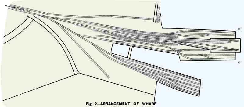
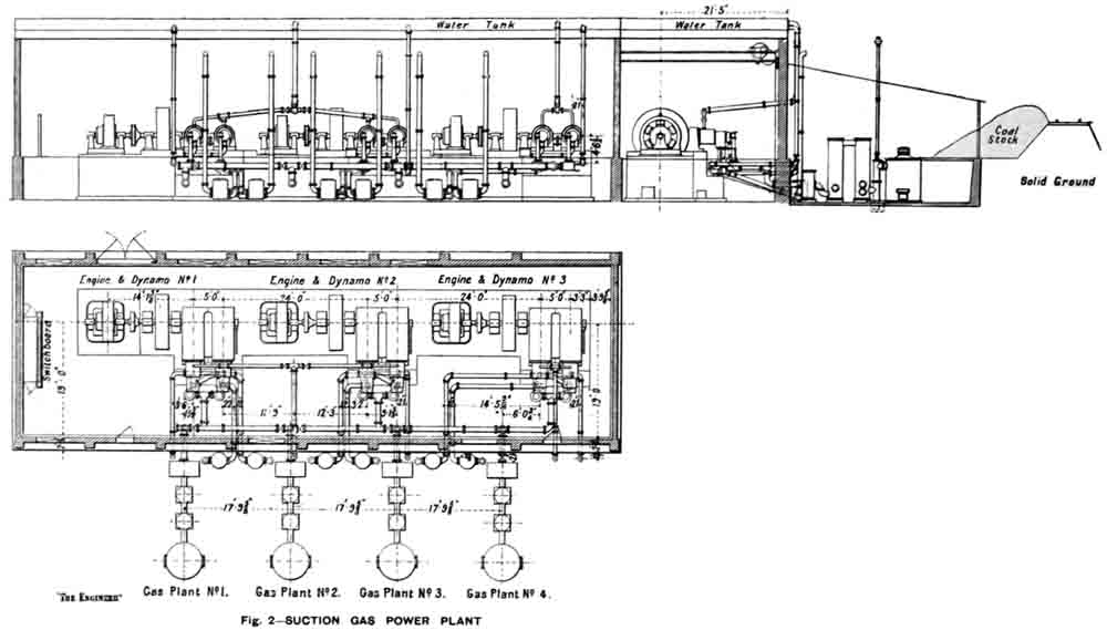
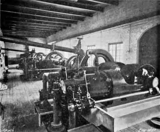

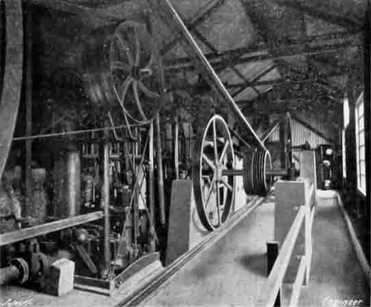 Figure 5: The Pump House, with two sets of
 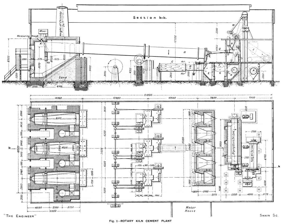 View
View 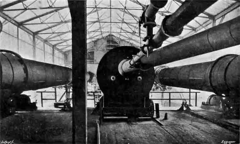 Figure 7: east-facing view of the kiln house from the firing floor.
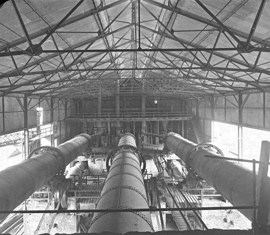 Figure 8: a higher-definition version of this from the Blue Circle Archive. West-facing view from the cold end of the kilns.
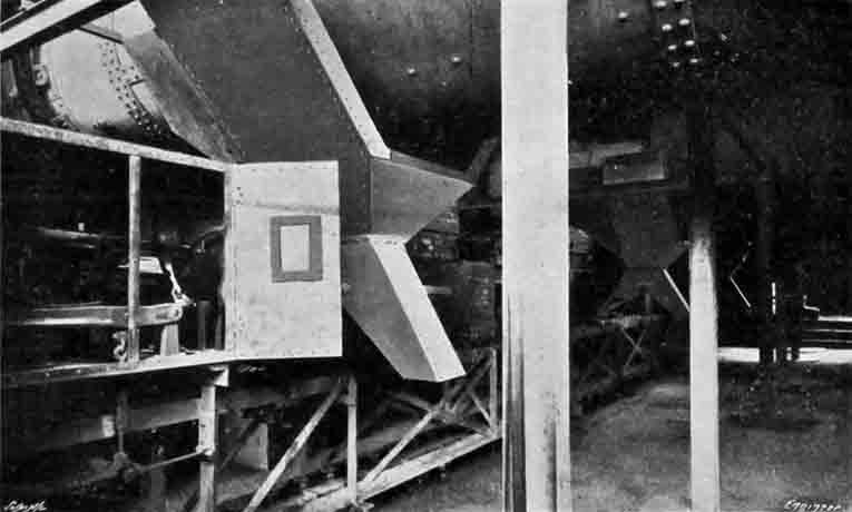 Figure 9: a view of the clinker conveyor carrying all three kilns' product, with a Denison weigher left foreground. The conveyor ran between the first and second piers, and No 3
 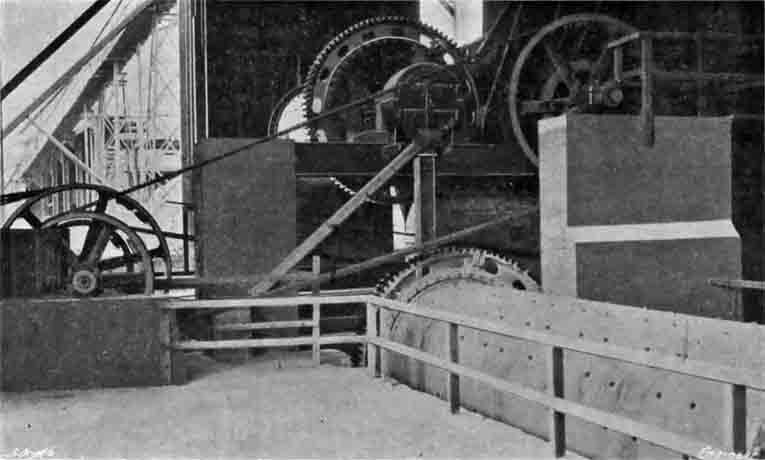 Figure 10: the new ball- and tube-mill set for finish grinding. This, I think, is an eastward view, and the overhead clinker conveyor from the kiln house can be seen through the door.
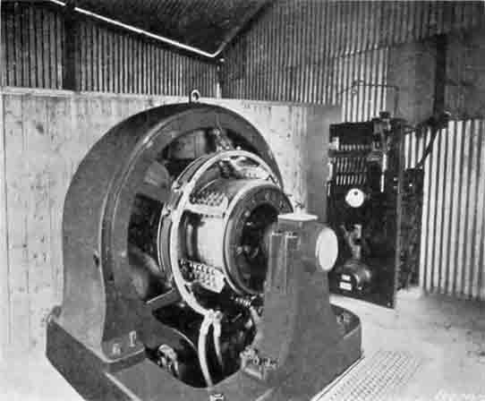
 Figure 17: Key Plan of Works
 Figure 4: Twin Screw Coal Feeder
 Figures 18 & 19: Cooler Chute Arrangement
 Figure 3: Rotary Slurry Feed
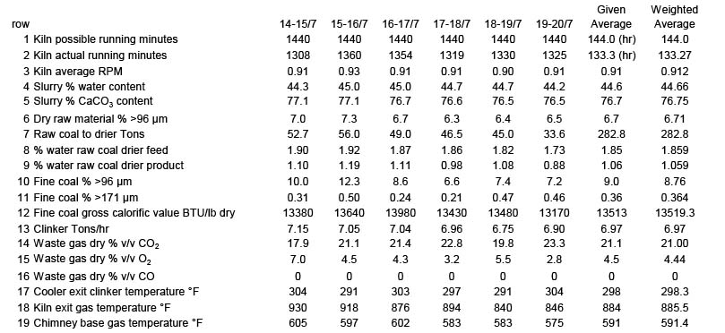
 Figure 20: Kiln Speed Chart 16-17/7/1919
 Figure 8: Rotary clinker weigher