The following is a transcript of an anonymous article that describes the Saxon and Norman cement plants. It appeared in The Engineer, CV, March 20, 1908, pp 294-296, 298. It is believed to be out of copyright.
The Grey Eminence who lurks in the background here is Arthur Charles Davis. See his detailed biography.
The article which follows was part of his promotion of the two Cambridge plants. The title reflects the fact that plants distant from the coast were still regarded as an oddity.
Values of imperial units (as of 1918) used in the text (alphabetical order): 1 acre = 0.40468424 Ha: 1 ft = 0.30479947 m: 1 gallon = 4.5460756 dm3: 1 HP (horse-power) = 0.7456998 kW: 1 inch = 25.399956 mm: 1 psi (pound-force per square inch) = 6.89478 kPa: 1 ton = 1.01604684 tonne: 1 yard = 0.91439841 m.
INLAND PORTLAND CEMENT WORKS.
It is an unusual thing to find Portland cement works having at their command a naturally-formed chalk marl which in everything save its "strength"—if we may be permitted to use such an expression—is exactly what is required to produce first-class cement. By the term "strength" we mean the relative proportions of chalky and clayey matter possessed by the marl. The Saxon Portland Cement Company, of Cambridge, with its sister works, the "Saxon" and the "Norman", has this somewhat distinct advantage. The site which it owns is underlaid with a vast deposit of marl in which the relative proportion of chalky to clayey matter varies from about 83 per cent. of the former and 17 per cent. of the latter to about 65 per cent. and 35 per cent. respectively. In all other respects the chalk marl, which has only a top soil of about 1 ft. or 18 in. in thickness, fulfils the requirements of first-class cement manufacture, and there is little, if any, flint present. There is no doubt that such a deposit is of very great value indeed, but the natural substance, if used exactly in the state in which it is found, would produce very inferior cement (Note 1). The proportions of chalk to clay which are necessary to produce good cement vary within very narrow limits. A divergence of 1 per cent. on one side or the other of a fixed line may—and in fact does—make all the difference between success and failure. This fact is very fully realised by the Saxon Portland Cement Company, and, consequently, we find its processes governed and directed with the greatest scientific care.
By the courtesy of Mr. A. C. Davis, Assoc. Inst. C.E., the managing director of the company, we recently had an opportunity of inspecting both the "Saxon" and the "Norman" works, and are enabled to lay the following description of them before our readers. In the case of both works we had the advantage of being shown over by Mr. C. F. Cooper, the chief engineer of the company. We had, therefore, every facility for obtaining accurate information regarding the different processes by which the cement is produced, for there is a considerable difference between the methods employed at the two works. It will be convenient if, in the first place, we describe the first works to be started—the "Saxon". These works were commenced in 1898, and got to work in 1901. They are situated some two miles north-east of Cambridge Station, and on the side of the main line from Cambridge to Newmarket, a siding from which is led on to the site. The marl is obtained from a quarry some 40ft. deep by means of a light railway and a steel rope manipulated by a steam winch. A single line only is employed, but there is a crossing place half way up the incline from the bottom of the quarry, where the full truck ascending can pass the empty truck which is descending. The various "strengths" of chalk marl occur in more or less well-defined strata. These are being continually analysed, and, by the direction of a chemist who is always on the spot, so much is taken from such and such a spot and so much from another, so as to make up each truck load. As each load gets to the surface a representative sample is taken from it, and this is analysed (Note 2) and a record kept of the results obtained. In this manner it is found that there is no difficulty whatever in keeping the proportions of the whole mass of material exactly to the ratios required. Moreover, testing is continually carried on throughout the various processes until the final cement is produced, for in this manner alone can uniform results be obtained.
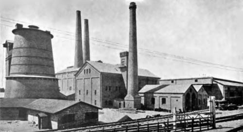
As it comes from the quarry the marl is in a more or less wet condition, this depending to a large extent on the state of the weather. In any case it has to be dried, and in the present instance this is done in a circular brick tower (Note 3) which, to some extent, resembles a hop kiln in outward appearance. We believe that this is the only example of a drying tower of this kind in this country (Note 4). To the upper part of this tower the loaded trucks are lifted in an elevator after being carefully weighed. The drying tower has in it two furnaces, which are constructed much in the same manner as is a coke oven, and they are fired with coal under forced draught. The heated gases pass up a brick cone in the centre of the tower, and impinge on the marl as it gradually descends. When it reaches the bottom it is in big lumps and is perfectly dry.
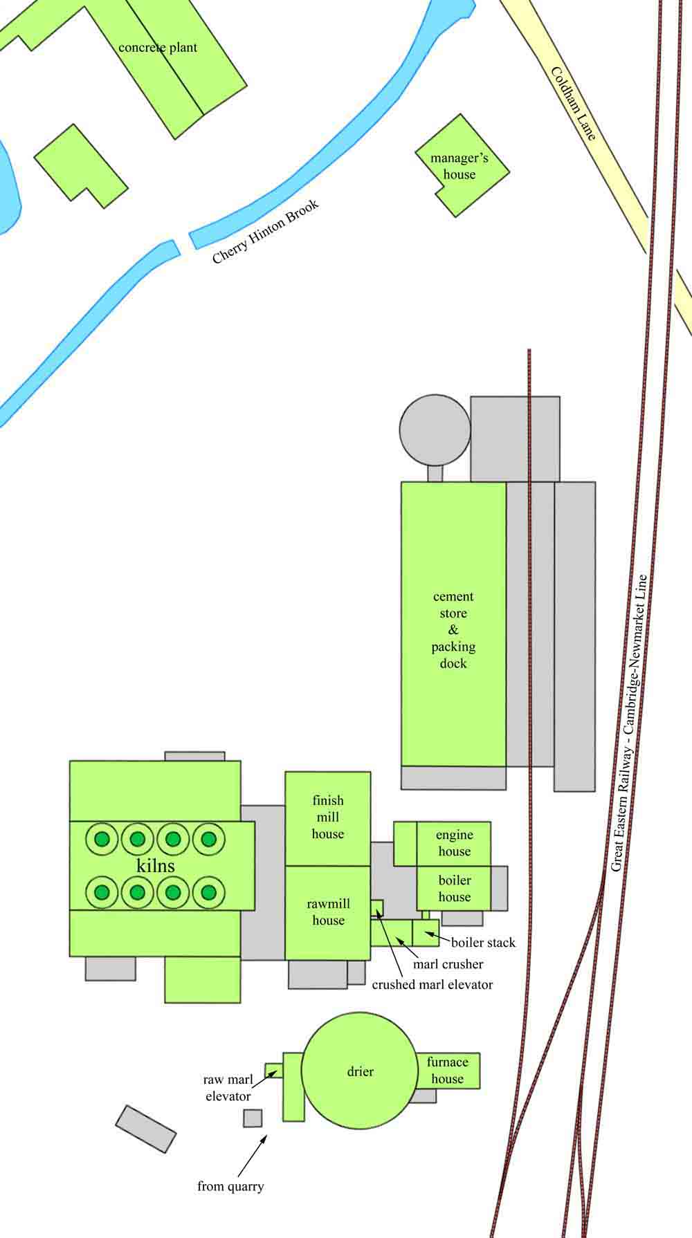 The article did not give a plan of Saxon: this is derived from the OS maps. Original buildings are in green, and later additions (to 1927) in grey. A C Davis liked to claim credit for the design of the plant, but inspection of the plan and the pictures leads to the conclusion that the plant was more-or-less entirely designed by FLS.
It comes out from a number of drawing eyes placed round the bottom of the tower; and it is then taken by a light railway to a perforated pan provided with edge runners. The bottom of this pan is perforated so that nothing having a greater diameter than ¾in. can leave it. What does come through is elevated and then allowed to descend to three tiger mills. From these mills the ground raw material passes through three separators, the discharge from which passes to a Griffin mill. When it leaves the latter it is in a very fine state of sub-division, so fine that no residue is left on a sieve having 5800 meshes per square inch (Note 5), and it is called " raw meal". It is not, however, in a condition to be burnt, for it is quite possible for it still to be in a somewhat unmixed condition. Portions of it may be very much weaker in chalk, and parts very much stronger than is actually required, and hence to make assurance doubly sure there arises the necessity for intimate mixing. For this purpose three large wooden bins have been provided, and into each of these in turn the raw meal is delivered. Inside the bins are special stirring appliances, and arrangements are made so that samples can be taken and analyses made by the chemists. Alterations can then be ordered should they be required. The usual practice is to have one mixer filling, one mixing, and one emptying at the same time. The actual mixing of the meal is brought about in the following manner:—The raw meal is delivered by a screw conveyor into one of the mixers, and as it falls into the hopper is caught by a series of rolls, which again empties into a conveyor at the bottom of the silo. From this conveyor an elevator lifts the material which has passed through the mixer, and delivers it to the feeding conveyor. The whole contents of one mixer is thus continually in circulation, and while this process is being carried on samples are continually taken for analysis by the chemist, who does not allow the raw meal to pass to the further stages of manufacture until the entire contents of the mixer are of the necessary composition to make a thoroughly good cement. When adequately mixed and passed by the chemist as correct, the meal is in a condition to be burnt. As, however, Schneider kilns, which we will describe a little later on, are used at these works, it is necessary beforehand to mould the meal into bricks. To do this the meal has first of all to be damped, and this is brought about in a horizontal trough in which revolves a worm conveyor. As the meal is taken along this trough by the action of the worm, the requisite quantity of water is added to bring the resulting paste to the necessary consistency. The mass then descends to either one of four Whittaker repress type brick presses, where it is formed into bricks 10in. long by 4in. wide by 3½in. thick, these bricks having their four corners slightly rounded. In this condition they are taken up to the charging floors of the Schneider kilns, which are in a building adjoining the crushing and mixture house.
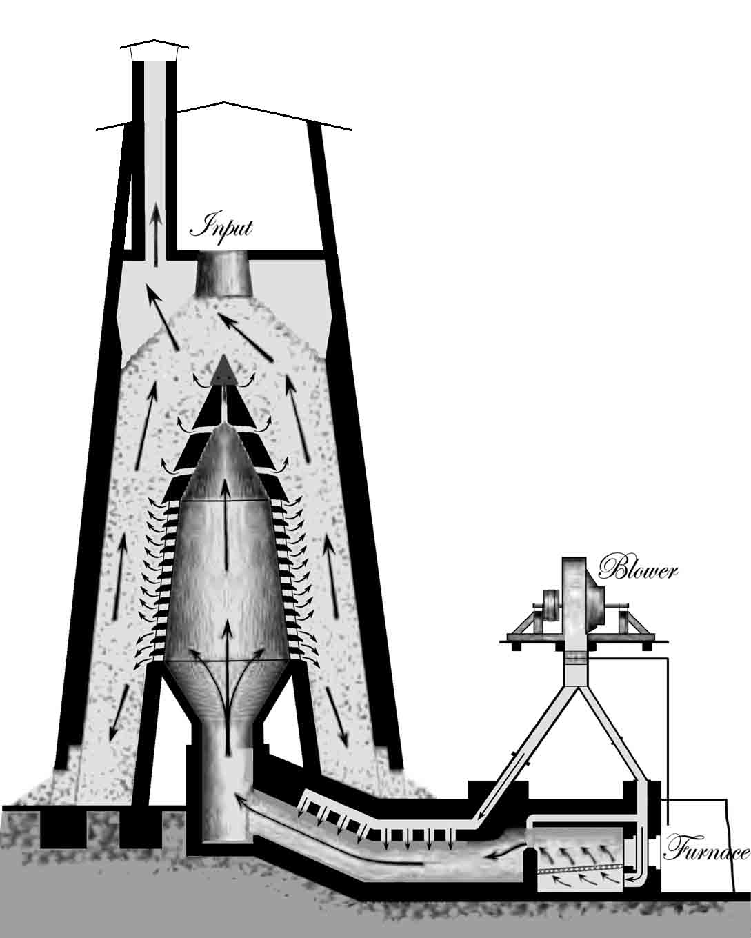
The Schneider kilns are in construction not unlike blast furnaces, but natural draught instead of blast is employed (Note 6). A sectional sketch of one of these kilns is given in Fig, 1. They are circular in form, are made of brickwork lined with firebrick. and are open at the bottom save for two upwardly sloping grates. When operations are commenced a substantial fire is laid on the grates, and above this are stacked alternate layers of coke and meal bricks. As the burning proceeds, alternate layers of coke and bricks are fed in from the top as shown in the illustration, there being a considerable art in charging these two materials correctly into the kiln. The actual charging takes place through openings at the top of the kiln, which openings are closed when the kiln is at work, and its top opening being connected to a chimney, there is sufficient draught properly to consume the coke and burn the bricks. When in full operation the fire zone is rather above the middle of the kiln, as shown in the illustration, the lower portion being termed the cooling zone. The cooling is brought about, of course, by reason of the large volume of air which is drawn by the draught up through the burnt clinker to provide for the combustion of the coke. Incidentally, this air is naturally heated and thus aids the process of combustion. The process of burning is continuous, the clinker being removed from the bottom as it falls from the grates, and new bricks of meal being fed in at the top at intervals. The quantity of fuel used in the bottom layers is greater than in those at the top, and as the loading of a kiln proceeds, the layers of raw material and fuel are also slightly reduced in thickness towards the top. By this means the desired heat is obtained more regularly over the kiln when it is fired.
As it comes from the kiln the clinker presents a regular appearance. In the lower layers there may sometimes be a few bits which are not thoroughly burnt, but these are not many, and are easily separated from the rest. It may be said that the time which elapses between the charging of a brick into the top of the kiln, and the time when it is withdrawn as clinker from the bottom is from three to four days. At the Saxon works there are eight kilns arranged in two rows of four kilns. Four of these are connected into one chimney and four into another, these chimneys being 150ft. high. The clinker on being removed from the base of the kilns is taken to a Krupp crusher (Note 7), where the big lumps are broken up into pieces about 2in. in diameter. In this condition it is raised in an elevator, and first passes through two ball mills, and from them to two tube mills, where the crushing and grinding to the requisite fineness is carried out. The ball mill, as most of our readers are aware, consists of a large drum or cylindrical chamber revolving on a central steel shaft and partially filled with hard steel balls of varying sizes. As the drum revolves these balls roll round inside it and crush the clinker by their action of falling one upon another. In the ball mills the size of the particles of clinker is reduced to from 0.05in. in diameter downwards. The tube mills into which the discharge from the ball mills is passed are horizontal steel cylinders 15ft. long and 4ft. in diameter. They are lined with a specially hard material, and are about half filled with flints of various sizes. They rotate at about thirty revolutions per minute (Note 8). The clinker grit is fed in at one end, and the attritive force of the flints falling one upon the other as the cylinder revolves is so great that practically any degree of fineness can be obtained. The average fineness worked to is, so we are informed. such that there is a residue of about 0.5 per cent, on a sieve having 5800 holes per square inch. and 15 per cent. on a 180 by 180 sieve (Note 9), though by reducing the quantity passing through the mills this fineness may be still further reduced.
As it leaves the grinding mills the finished cement is lifted in an elevator and delivered into a spiral conveyor which carries it to the cement storehouse which adjoins the grinding house. Numerous outlets are provided in the conveyor so that the cement may be delivered into any desired bin. The stores at the Saxon works are capable of holding some 7000 tons of cement. The weekly output from these works is, we understand, well over 800 tons a week, which means that each kiln produces over 100 tons in this time.
The power is derived from two Lancashire boilers fitted with Bennis automatic stokers. There is a Pollit and Wigzell's horizontal compound tandem jet condensing engine of 470 indicated horse-power. The condensing water is cooled in two ponds. The water supply for the works is obtained from a deep well, from which the water is raised by a direct acting pump, of which the steam cylinder is fixed vertically at ground level. The works are lighted throughout by electric light, the current for which is obtained from a compound wound dynamo working at 230 volts and driven by a vertical Davey-Paxman engine (Note 10). Another dynamo is driven off the main shafting. this being used to supply current to the works of a subsidiary company, of which Mr. Davis is also managing director. In this works. which are known as the Atlas Artificial Stone Works, and which are situated on land adjoining the Saxon works, a great variety of artificial stonework is manufactured by treating a mixture of granite chips and cement by means of hydraulic pressure. The chief articles which we saw in course of manufacture were paving blocks and staircases, but we gathered that a good many other things were made, and that the output from these works was regular and considerable.
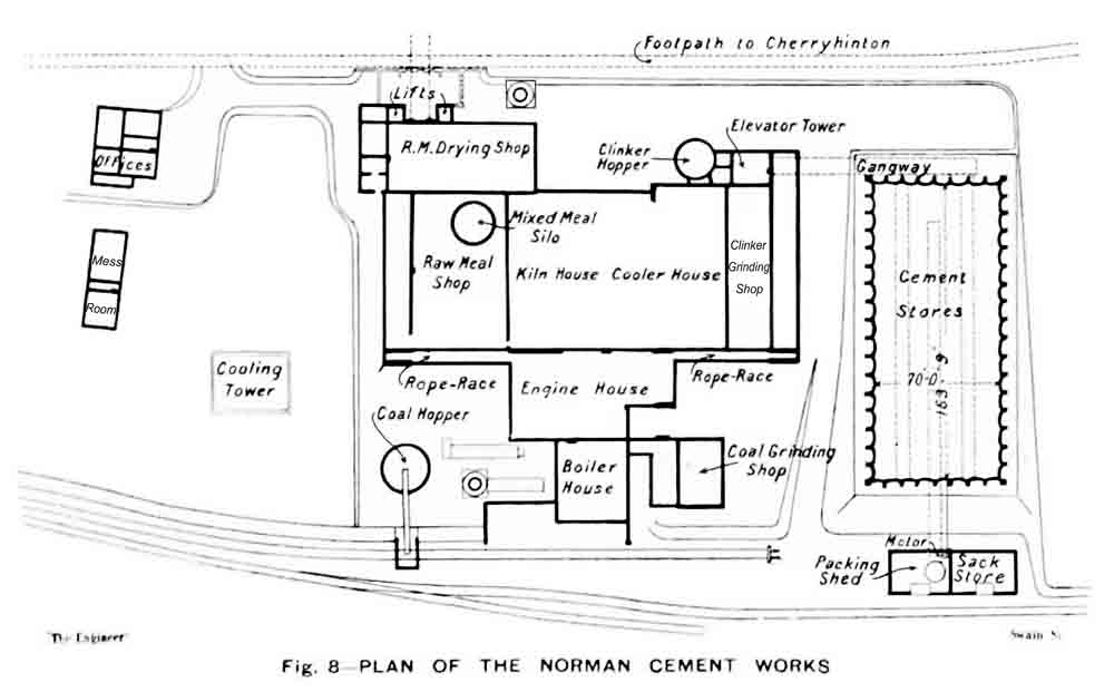 Figure 8: Plan of the Norman plant.
It became evident very shortly after the Saxon works had been started, that there was a call for more cement than they could supply. Accordingly, it was determined to erect the "Norman" works, which are about half a mile away, and situated on a deposit exactly similar to that on which the first-named works stand. The science of cement-making had, however, advanced considerably in the intervening time, and the use of rotary kilns become much more general (Note 11). It is not surprising, therefore, to find the Schneider kiln passed over for the newer form. The rotary kiln consumes rather more fuel per ton of cement than does the Schneider (Note 12)—at least, that is the experience at the Norman and Saxon works—but the cement produced by the former of an exceedingly well-burnt and regular character, and, moreover, less floor space is required for a given output, and there is not so much labour required. There are other points of difference between the two works, as will be seen from the following description.
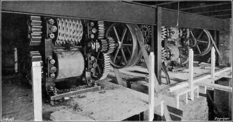 Figure 9: the marl crushers. These are probably Krupp crushers as used also at Saxon.
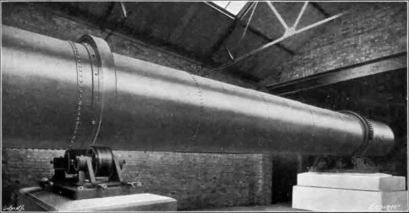 Figure 10: a rotary marl drier.
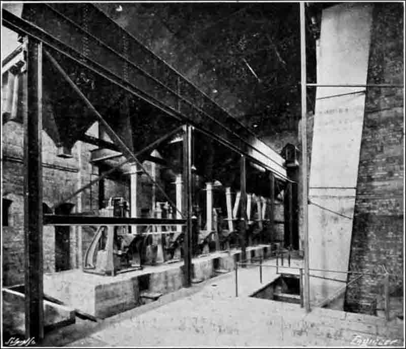 Figure 4: Griffin Mills used as rawmills.
The marl is taken from a quarry which is some distance from that which feeds the Saxon works (Note 13). It is, however, dealt with in a precisely similar manner, the excavators (Note 14) working at different faces so as to produce the regulation mixture of ingredients. At the top of the incline leading from the quarry, up from which the trolley tubs are drawn by wire rope, there is an analysing workshop. As each tub comes up, samples are taken and at once analysed. If the proportions are not correct, then alterations are ordered; but, as far as our observations went, the navvies had so accurately followed the direction of the chemist as to what quantities to take from various parts of the faces of the quarry that the proportions of the raw material were made very nearly correct from the outset. This, however, did not cause any relaxation of inspection. Analyses and tests are being continuously carried out, and there are three separate laboratories throughout the works, which are under the charge of the chief chemist, Mr. R. Kirkland.
The drying tower mentioned as being used at the Saxon works is not repeated in the newer establishment. In its place are two cylindrical drying drums, which are heated by the gases in the flues leading from the rotary kilns. The trucks of marl are first of all taken by either of two lifts to the top of a tower. Here the marl is passed through two crushers—see Fig. 9—which break up the lumps and produce pieces some 2in. or so in diameter. In this form the marl descends by gravity to the two rotary drying drums. These, in form, are very similar to rotary kilns, only they are smaller. They are, however, carried on roller bearings, and are rotated in exactly the same way—see Fig. 10. The heat to which the marl is subjected in these drums is very high (Note 15), and the consequence is that every particle of moisture is removed, and the bits of marl become quite hard and friable.
In this condition they are taken by an elevator to the raw meal mills, which are of the Griffin type. They are seven of these arranged in a line, as may be seen in Fig. 4, and fed from an overhead hopper into which the dried marl is delivered. All the seven machines are mounted on a solid block of concrete, and the vibration is but slight.
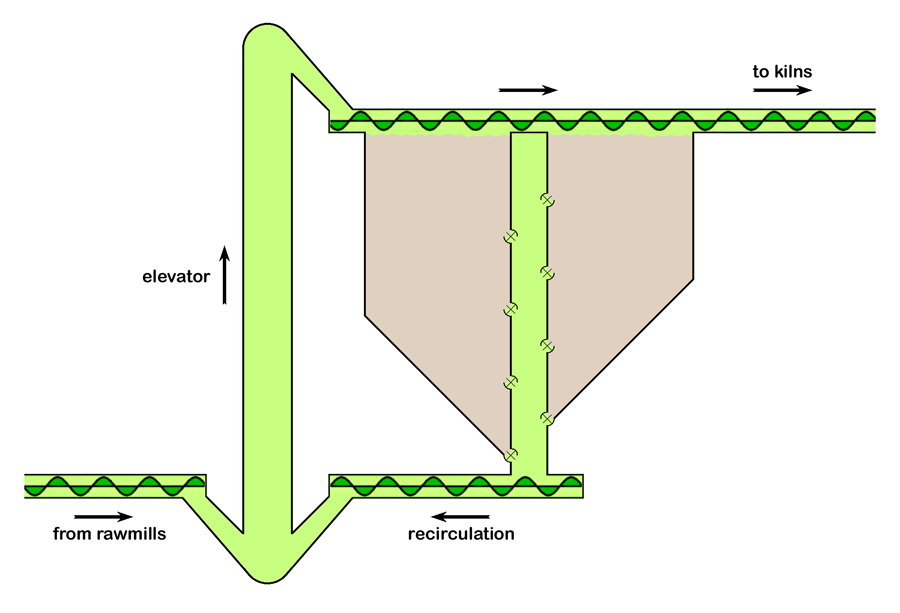 Simplified layout of the "Raw meal mixer"
The discharge from these is elevated to the top of a mixer, in which a very intimate mixture of the whole mass is brought about in the following manner:—The finely-ground raw meal is delivered by a screw conveyor and drops on to a series of shelves, forming different sections of the mixer silo. From these shelves a butterfly feed drops a certain quantity of the raw meal from each shelf into the centre portion of the mixer, there it is caught by a screw conveyor and elevator, and emptied into the conveyor feeding the mixer. When the mixing is complete the meal has arrived at the bottom of the mixer, and we should state that during the whole process analyses are going on, and when of a correct composition it is elevated to a storage silo from which the rotary kilns are fed (Note 16).
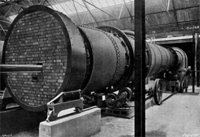 Figure 11
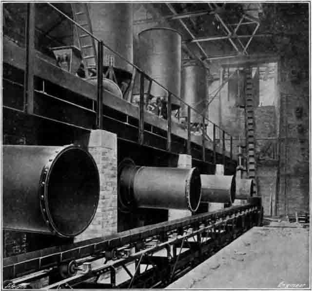 Figure 2: Outlet end of coolers. The coolers are below the firing floor, and the fine coal hoppers can be seen above. One can assume that the rather pitiful clinker conveyor shown was soon replaced with something more substantial.
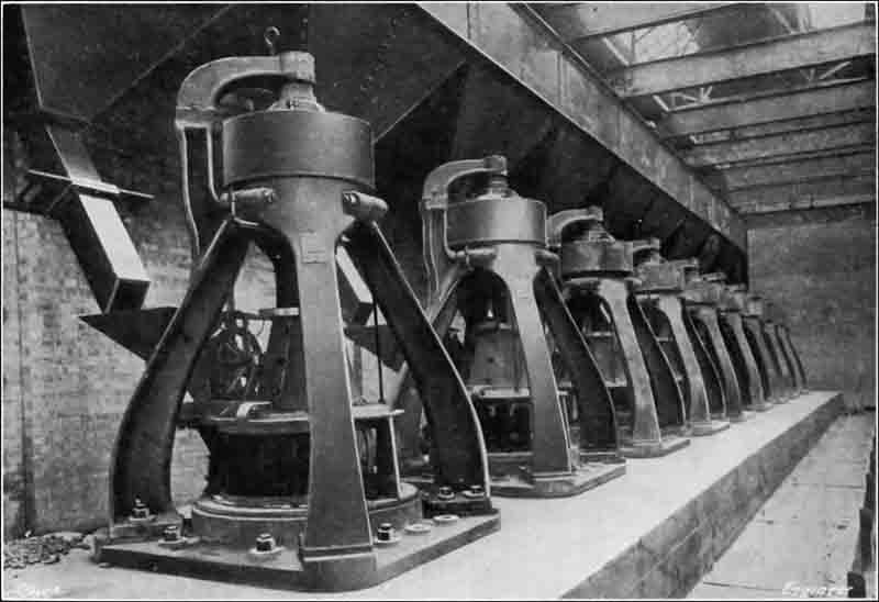 Figure 12: Set of nine Griffin mills used for finish milling.
There are in all five rotary kilns of the form shown in Fig. 11. These are 60ft. long and 7ft. 6in. in diameter (Note 17). They are fired with powdered coal, which is driven into them by air blast derived from fans. The coal is, of course, well dried before being ground. When arriving on the sidings, the trucks of coal are emptied into an elevator feeding a coal silo of some 500 tons capacity. From there the coal is fed into a rotary drying drum, which is heated by the waste gases from the kilns.
It is then taken to crushers which deliver into Griffin mills, of which there are three. The powdered coal as it comes from these is so fine that there is only 1 per cent. residue on a sieve with 100 by 100 meshes per square inch. In this condition it is taken by an elevator to a worm conveyor running over a series of five hoppers, one being arranged for each kiln over the firing platform. Three of these may be seen in Fig. 2. The casing of one of the blast fans may also be observed. There is one of these fans to each kiln. Each one draws its supply of air through the clinker cooler corresponding to the kiln which it controls. The ends of four of these coolers may be seen in Fig. 2. They are cylindrical form, and are made of steel, being some 30ft. long and 4ft. in diameter. They are arranged slightly on the incline. The glowing clinker, as it is discharged from the ends of the kilns, falls by gravity into the higher end of the coolers, and as the latter gradually revolve, it is taken slowly down towards the discharging ends shown in Fig. 2. Meanwhile it has become considerably cooled—so much so that the smaller pieces may be picked up with the fingers. Naturally, therefore, the air which has been drawn over it is correspondingly heated, and in this condition it is delivered into the kiln, taking the coal along with it. The amounts of coal and air can be regulated at will, there being a variable worm feed for the former.
The clinker produced is some of the best burnt we have ever seen, and is wonderfully regular. It has a noticeably dark colour; in fact, it may be said that the cement produced at both the Norman and the Saxon works are a bit darker in colour than other kinds of cement, and that that coming from the former is slightly the darker of the two.
As it comes from the coolers, the clinker is caught on a travelling tray conveyor and is deposited into a hopper at the far end of the building, from which it is lifted by the elevator which may be seen in Fig. 2 and delivered into the hopper of the clinker crusher, where it is broken up into fairly small pieces. It is then again elevated to the hoppers above the clinker grinders. These are also of the Griffin type, and there are nine of them—see Fig. 12. Practically any degree of fineness can be obtained in these mills, but unless it is otherwise specified the British Standard Specification is worked to (Note 18). The finished cement is again elevated and delivered into a conveyor which takes it to the stores, where it in turn delivers it into another conveyor running the whole length of the building.
These stores form quite a feature of the works. They are constructed to hold up to 15,000 tons of cement. The upper side walls are formed of a series of semicircular brickwork, and the shape of the bottom—which is made of concrete—is that of an inverted cone with a triangular division piece running the full length of the store in the centre at the bottom. This division piece supports a series of joists which carry the roof, and is constructed over a culvert or passage way which runs underneath the whole of the store. A number of gratings may be observed on either side of the division piece. These lead to shoots connecting with feeding devices in the culvert, along the whole length of which runs a worm conveyor. Cement can therefore be drawn from a number of different parts in the stores, all the feeding devices being provided with shutting-off valves. As the cement descends to this conveyor it is taken along to the end of the building, where it is delivered into a hopper, from which it is lifted by an elevator into hoppers over Savory automatic weighing machines, which weigh out and deliver automatically into sacks the required amount of cement, which is hence not touched by hand from the very commencement after it leaves the quarry right up to the time of delivery, and then only it is the sack which contains it and not the cement itself which is handled. As each sack leaves the works a small sample is taken from it for testing purposes. The sacks are filled in a room the floor of which is at the same level as a platform of a railway siding, and the sacks as soon as the weighed quantity of cement falls into them are at once wheeled on hand trucks into a covered railway wagon. The machinery in the cement packing, weighing, and shipping stores is driven by an electric motor.
As was to be expected, the power required at these works is considerably in excess of that necessary at the Saxon works. There are, to begin with, three Babcock and Wilcox boilers working at a pressure of 140 lb. per square inch, the steam being superheated 100 deg. Fah. The boilers are fitted with chain grate stokers, and have sufficient capacity to supply steam to the three engines, to which we shall shortly refer; steam pumps, jets, etc., in various parts of the works amounting in all to some 1000 indicated horse-power. There is also a Green's economiser with 160 tubes, and the feed-water is supplied at 180 deg. Fah. The largest engine supplied by these boilers indicates some 750 horse-power. It is of Pollit and Wigzell's horizontal compound tandem condensing design, the condenser being of the jet type. The next largest engine indicates 200 horse-power, is of the same type, and is fitted with Corliss valve gear. Like the first engine, it has a jet condenser, In Fig. 8, which is a plan of the works, the engine-house may be seen abutting on the kiln house. The fly-wheel of the large engine revolves parallel to the wall between these two houses, and drives both ways into the rope races shown, thus commanding the raw meal drying shop, the raw meal grinding shop, the kilns and coolers, and the clinker grinding shop. The 200 horse-power engine drives the rotary kilns and coolers on Sundays. The third engine is a smaller horizontal engine indicating 70 horse-power. It drives a dynamo for the lighting of the works and quarry (Note 19). The former are served by 400 30 candle-power incandescent lamps, and the latter by flame arc lamps. The condensing water is cooled in a tower, and the water supply is obtained from a deep well, as at the Saxon works. There is a small engineers' shop for repairs, and the machine tools in this consisting of lathes, drilling, punching, and shearing machines in this, as well as a smith's fan, are also driven by an electric motor driving on to a line shafting. The coal is lifted direct from railway trucks on the siding into a large circular hopper, capable of holding 500 tons. From this it can be drawn as required. The output of the Norman works of the Saxon Portland Cement Company is over 1200 tons a week, making a total output of over 2000 tons a week for the both works.
Before leaving this interesting subject, we may perhaps say a few words about the characteristics of the cement produced. The following comparison between the requirements of the British standard specification and what is guaranteed to do is instructive: –
| British Standard Specification | Saxon Portland Cement | |
|---|---|---|
| Tensile Test: Neat Cement | ||
| 7 days psi | 400 | 600 |
| 28 days psi | 500 | 800 |
| Tensile Test: Standard Sand and Cement, 3 to 1 | ||
| 7 days psi | 150 | 250 (7.5)A |
| 28 days psi | 250 | 350 (13.7)A |
| Fineness | ||
| % residue No 76 sieve | 3 | 2 |
| % residue No 180 sieve | 18 | 15 |
| Specific Gravity | ||
| 3.15 | 3.15 | |
| Soundness | ||
| Le Chatelier test, mm | 5 | 1.5 |
Note A: values in brackets are corresponding modern EN 196 compressive strengths in MPa.
We ourselves saw a neat cement briquette 28 days old broken at 1000 lb., and we have one before us of the same age which is marked as having broken at 1120 lb., as well as a three to one sand briquette which is marked as having broken at 550 lb. at 28 days. It is claimed for the Saxon cement that it practically does not expand at all on setting. We have a test tube — one of some hundreds, that we saw—which is quite full and is un-cracked. We have also seen a pat put under water as soon as it was formed and remain perfectly sound.
NOTES
Note 1. This was a direct challenge to the many Cambridgeshire firms who claimed to have a raw material "so perfect" that it could be burnt in its as-dug state.
Note 2. Although the amount of chemical supervision done was probably considerably greater than at most plants, the amount seems to be considerably exaggerated in the article. Assuming the plant was making 800 tons a week, requiring 1500 tons of marl in a quarry working week of 90 hours at most, 8-12 skips of marl were being handled per hour. It is unlikely that they were analysed individually.
Note 3. This was a Smidth Drier.
Note 4. The Smidth drier was a fairly standard part of the package with shaft kilns - Aalborg and Schneider - supplied by FLS, and was a common feature on continental plants. The one at Saxon was certainly the first. Burwell had installed one around 1904. To my knowledge, none of the other British plants had one.
Note 5. This is about 200 µm.
Note 6. Peter Jackson says they had forced draught. The output of the kilns given here was possible on natural draught.
Note 7. Clinker from static kilns emerged as irregular shaped lumps, and boulders of 0.5 m or more were common. Any sort of fine-grinding mill needs its feed to be below 50 mm in size.
Note 8. If the internal diameter is 3ft 8in, this is 75% of critical speed.
Note 9. These sieves are about 200 µm and 85 µm respectively. Sieves were the only method of particle size analysis available, and these data are not at all informative. There is a particular difficulty when considering the different milling systems at the two plants, since the amount of "flour" (i.e. material below 25 µm), which mainly controls the cement's properties, can be vastly different for a given 85 µm value. The fineness here was probably around 34% above 45 µm, with a specific surface of around 264 m2/kg.
Note 10. As is typical of plants around 1900, the power for all the machinery - crushers, rawmills, presses, finish mills, elevators and conveyors - was provided by a single steam engine, with belts and pulleys on a lay-shaft. The only use of electricity was for lighting.
Note 11. In my current (Jan 2016) database, 54 rotary kilns were in place when the Norman kilns started, at Shoreham, Swanscombe, Wouldham, Martin Earles, Penarth, Newhaven, Arlesey, Stoneferry, Bevans and Billingham.
Note 12. Until the last were shut down in the mid-1930s, well-run Schneider kilns remained the most fuel-efficient kilns in operation, even if fuel for drying is included. In Britain, the first rotary kiln to achieve better efficiency was at Cauldon, as late as 1957.
Note 13. The quarry lands - on both sides of the railway - of both plants were subsequently merged.
Note 14. Meaning men with picks and bars - mechanical quarrying only began in the 1920s.
Note 15. The kiln exit gas temperature was 800-900°C, so there was a considerable excess of drying energy available.
Note 16. The problems involved in this early attempt at dry blending are discussed in the raw material preparation page. The mixer was designed by William Gilbert and David Butler.
Note 17. An inexact treatment of kiln dimensions was the rule in these articles. From the diagram "based on working drawings" given in Butler's 1913 edition, the kilns appear to be metric with a 2.25m diameter in the front 9 m, followed by a 4.5 m cone, then a diameter of 1.9 m for the remaining 4.5 m. The Fellner & Ziegler kilns supplied to Swanscombe in 1901 were alledgedly supplied to Imperial dimensions, but those supplied to Southam in 1908 were metric.
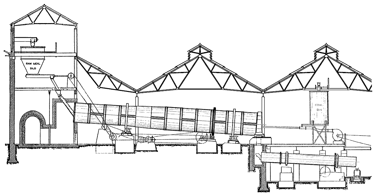 Figure 21 from Butler's 3rd Edition shows this anonymously as a "typical" dry process, but it's obviously Norman's original Fellner & Ziegler kilns.
Note 18. As mentioned in Note 9, the Griffin Mills, operated to give a 90 µm residue slightly below the British Standard maximum, would have yielded a cement much coarser than that produced by the ball-and-tube mill at Saxon. With the two plants combined after the BPCM takeover, Norman clinker was usually moved to Saxon for grinding. When the plant was uprated in 1922, a combination mill was installed, although the Griffin mills were kept for pre-grinding. They were finally taken out in the mid-1930s when a second combination mill was added.
Note 19. It can be seen that electrification had progressed little in the intervening three years. Only two electric motors have been installed - one for the packer and one for the fitting shop, and the main plant is still all run from a single steam engine.
 Rather fanciful views of the plants from a letter-head of the period