The following is based on anonymous articles describing the plant as originally constructed. One appeared in Cement and Cement Manufacture, III, 1930, pp 55-68. Another was a pubicity pamphlet published by BPCM in 1929, including much the same text and pictures. Both are believed to be out of copyright. Both are provided, since they have somewhat different emphasis - the pamphlet was designed for a less technical audience, but contains more information.
Values of imperial units (as of 1929) used in the text: 1 inch = 25.399956 mm: 1 ft = 0.30479947 m: 1 cubic ft = 0.0283167 m3: 1 ton = 1.01604684 tonne: 1 HP (horse-power) = 0.7456998 kW: 1 psi (pound-force per square inch) = 6.89478 kPa.
First, the article in Cement and Cement Manufacture:
The New Hope Cement Works of Messrs. G. & T. Earle, Ltd.
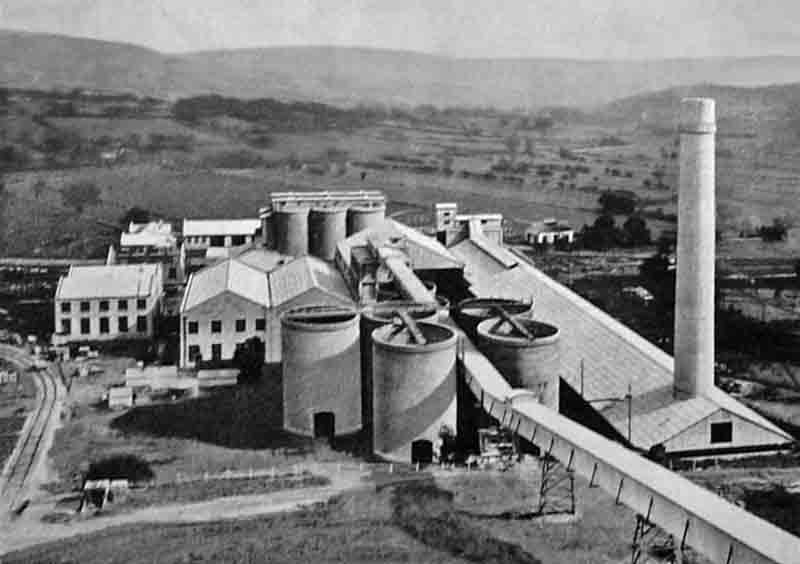 Figure 1. View of the plant from the quarry.
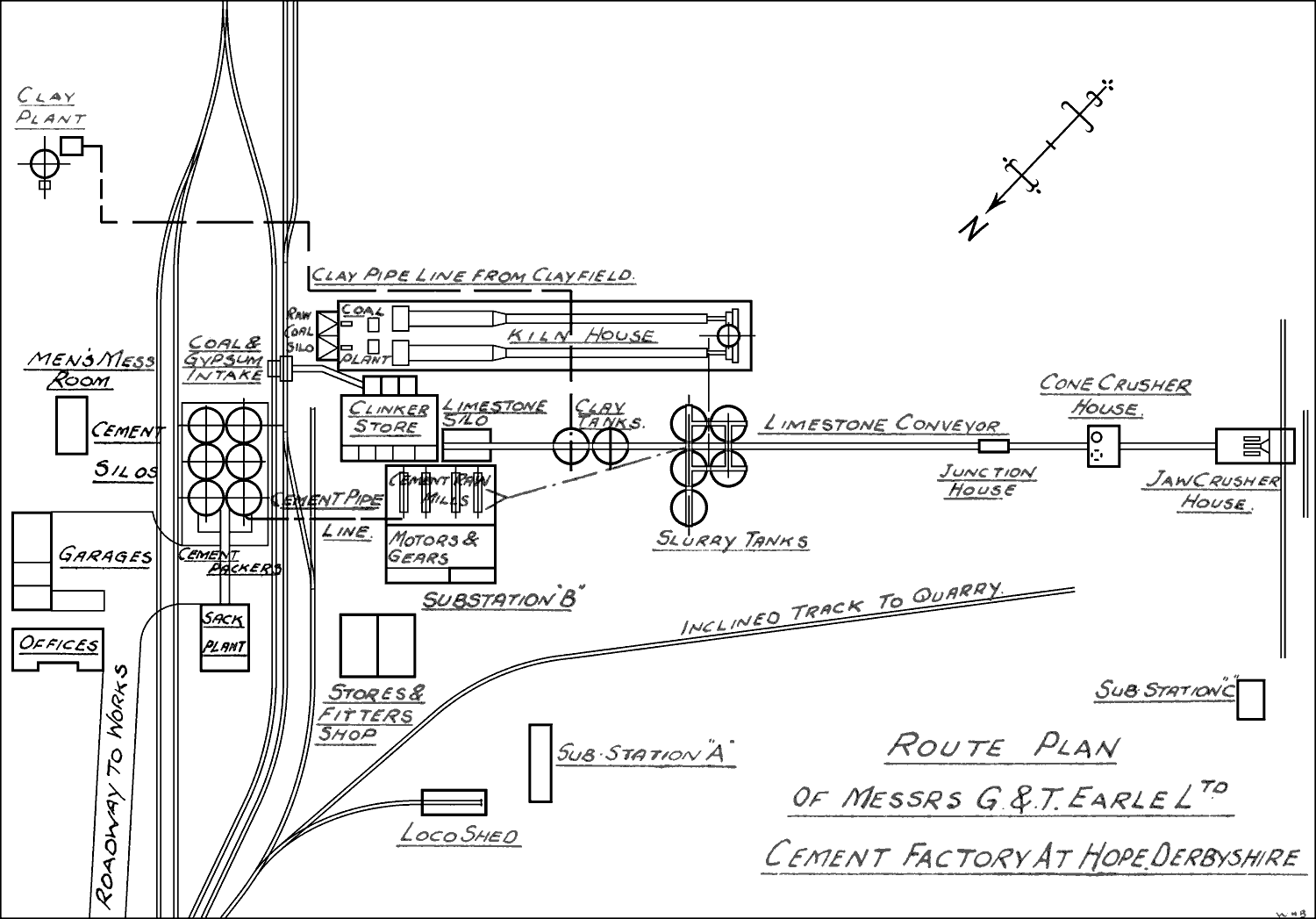 Figure 2. Sketch plan of the plant.
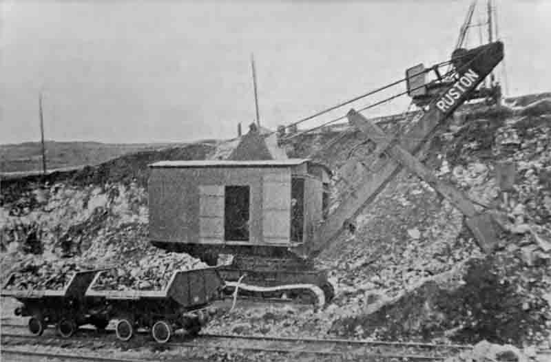 Figure 12. Ruston & Hornsby electric shovel loading blasted limestone. The drill-rig is in the background.
Manufacture of Portland cement was recently commenced at the new factory of Messrs. G. & T. Earle. Ltd., cement manufacturers, of Hull (Note 1). The site selected is at Hope, on the south-eastern border of the High Peak district of Derbyshire, about midway between Manchester and Sheffield. A private railway connects with the Dore and Chinley branch of the London, Midland and Scottish Railway Company, while road transport for the finished product will be facilitated by the construction of a concrete road from the works to the main road leading from Hathersage to Castleton. A brief summary of the directions in which accepted practice has been departed from, and new ideas so far as Great Britain is concerned are now being tried out, will be of interest.
For the first time a gyratory crusher for fine crushing in cement works is being used (Note 2). Exit gases are led directly into dust-collecting fans. Only three elevators have been fitted throughout the works; one of them lifts coal from the railway wagons into the storage hoppers, the second is for fine coal storage, and the third restores dust from the kiln induced-draught fans back into the kilns. The processes of crushing, grinding, kiln slurry feeding, and the preparation of the clay are all accomplished without the aid of a bucket elevator. There is no tramway in connection with clay-winning and washing. The clay is dragged by scraper gear direct from the clay-field into a clay washmill and thence pumped into storage.
The factory is laid out for a cement production of 3,200 tons per week and arranged with a view to future extensions (Note 3). On visiting the site attention is immediately arrested by the hilly nature of the ground, and one appreciates that the lay-out of the quarries and plant has been to a large extent determined by the contours of the ground. The quarry floor is 875 ft. above ordnance datum, the works themselves finish with the clay washmill at 570 ft. O.D.; thus there is a difference of 305 ft. from highest to lowest levels.
The Quarry
The limestone is of high quality, practically free from moisture, and contains 97 per cent. of calcium carbonate. A quarry face about 700 ft. in length was opened during the construction of the factory in preparation for large-scale blasting. Shortly before manufacture commenced, the drilling of this face was completed, and at one operation about 30,000 tons of limestone were dislodged and broken to a suitable size for picking up by the electric navvy. The holes, drilled by well drills of the company's own manufacture, were 6 in. in diameter by 35 ft. deep and were exploded simultaneously.
The broken limestone is picked up by an electric navvy with a bucket of 3½ cu. yd. capacity and caterpillar wheels for travelling. The slewing of the jib is accomplished by a self-contained unit operated by its own motor; in fact, a separate motor is provided for each motion. A 110-HP motor takes care of the hoisting, while slewing and racking each has its own 40-HP power units. Each of the three motions is controlled by a separate reversing-contactor type stator panel with mechanical and electrical interlocks and over-load relays. Master controllers fitted with vertical hand-levers actuate these contactors, while two-pole overload protection is provided throughout. Clutches are operated pneumatically with a minimum of effort from the chargeman. The controls provided fully protect the motors, which can be stalled for a considerable interval without damage.
The two electric locomotives used to convey the limestone from the quarry face to the crusher house are each driven by two 27-HP motors and are capable of taking a 50-ton load up the steepest quarry gradient, which is 1 in 50, at a speed of 10 miles per hour. Direct current is collected by two collector shoes in contact with a third rail in the centre of the track. The 400-volts 3-phase current is converted to a 250-volt D.C. supply with earthed return to provide the necessary power for these locomotives. Steel wagons of standard gauge and of 7-cu. yd. capacity are used for conveying limestone to the crusher house.
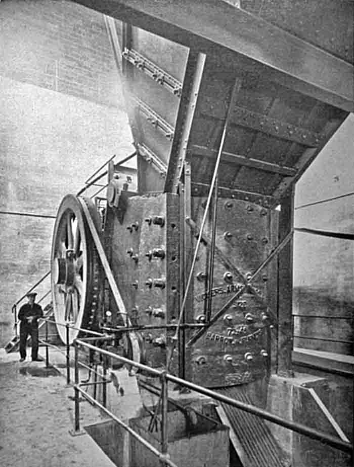
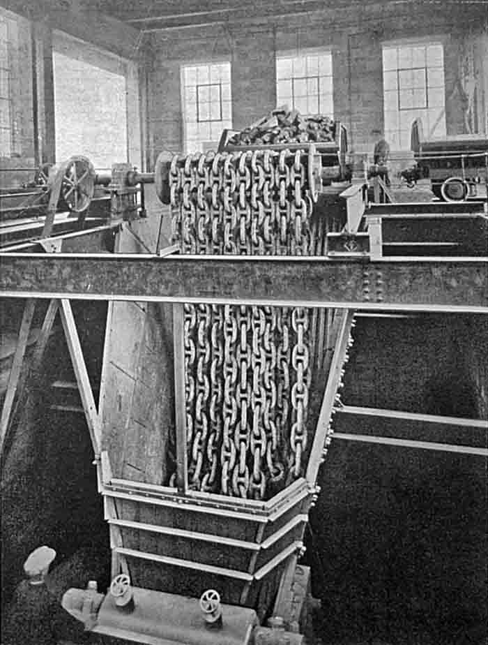 Figures 5 & 6. Primary jaw crusher - Ross feeder right, with a 9-ton wagon of stone about to be tipped. It was later replaced with a gyratory crusher.
In the crusher house building is installed the largest jaw crusher yet built in England, having a 6 ft. by 4 ft. opening and weighing about 133 tons. It is capable of taking blocks of stone weighing five tons and crushing them down to 6 in. size, the output being about 250 tons per hour. This crusher is driven by a 250-HP motor, and the crushed stone proceeds to a secondary crusher of the gyratory cone type.
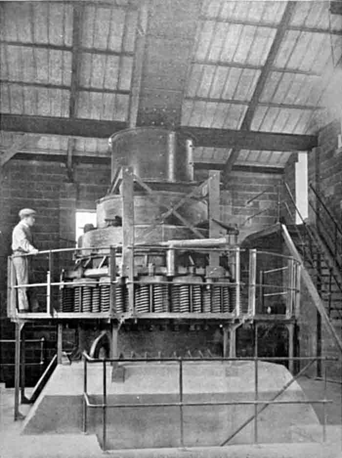 Figure 7. Symons secondary cone crusher.
The latter crusher differs from the usual run of gyratory crushers in that it has a very much higher speed (about 450 r.p.m.) and the cone is flattened towards the base. In the standard gyratory crusher the largest size stone which can fall through is determined by the distance between the cone and casing at its widest. In this fine crusher, however, the flattened cone and the high speed delay the exit of the crushed material for at least one complete revolution of the mill. It therefore follows that the largest size stone is regulated by the distance between the closed side of the cone and the casing, and not by the open side. The shock of the crushing is taken by about forty spiral springs, the tightness of which, and the size of the crushed product, can be regulated while the machine is running. The weight of this crusher is about 50 tons and its output 225 tons per hour when crushing down to ½ in. size from 12 in. blocks. It is the largest crusher of its type in England.
There is a drop of 198 ft. down the hillside between the jaw crusher entrance and the top of the limestone silos, and this has to be provided for. From the quarry floor to the jaw crusher the stone falls 28 ft. and from thence to the secondary cone crusher intake a belt conveyor 353 ft. long by 42 in. wide lowers the stone a distance of 59 ft. to the cone crusher. The final descent down the hillside is by a chute in which heavy chains are arranged to check the flow of the stone before reaching a belt conveyor which conveys it to the limestone silo. This silo is built in reinforced concrete and has a capacity of 2,000 tons of stone, and from here the crushed limestone is led direct to the feed tables of two combination mills each 36 ft. long by 7 ft. 2½ in. diameter and driven by 650-HP auto-synchronous motors through reduction gearing.
The raw mills, as well as the dry mills mentioned later, are driven direct from the reduction gearing through a coupling and shaft fixed to the mill in line with the axis, thus dispensing with the pinion and spur-ring wheel usually provided for tube mills (Note 4).
The slurry from the raw mills is run through a motor-driven mechanically-vibrated screen which takes out any coarse matter before the slurry passes to the centrifugal pumps which convey it to the storage tanks. The slurry storage is accommodated in five reinforced concrete tanks each of about 17,000 cu. ft. capacity (Note 5), which have no mechanical stirring gear but are provided with compressed-air mixing arrangements through fixed pipes at the bottom of each tank.
Clay Plant
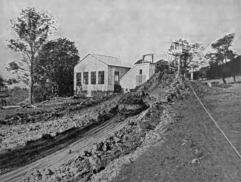 Figure 11. Dragline in clay field.
In the clayfield a washmill of 20 ft. diameter, provided with a 104-HP motor, washes the clay at the rate of 60 tons per hour, from which point it is pumped to the works by plunger pumps into two clay tanks each holding about 620 tons of clay. The method of winning the clay is by means of a scraper digger having a 3-yd. bucket and capable of an output of 60 tons per hour with a maximum length of haul on the ropeway of 830 ft. A 150-HP motor provides power for this scraper, which, working one shift per day, provides clay sufficient for the output of the factory.
From the clay washmill the "slip" is pumped to the works 780 yds. distant, where it is stored in two clay tanks each holding 620 tons of clay "slip". From these tanks the "slip" gravitates through a float-valve into a measuring tank from whence two bucket wheels with variable-speed control supply measured quantities to the mills, also by gravity (Note 6). The means by which the "slip" in the measuring tank is kept at constant level by means of a float valve is of interest. The float, instead of acting directly upon the valve, is fitted with contactor gear and a small motor which turns the valve wheel backwards and forwards according to the varying pressures from the clay tank and the filling requirements of the mills.
Kiln House
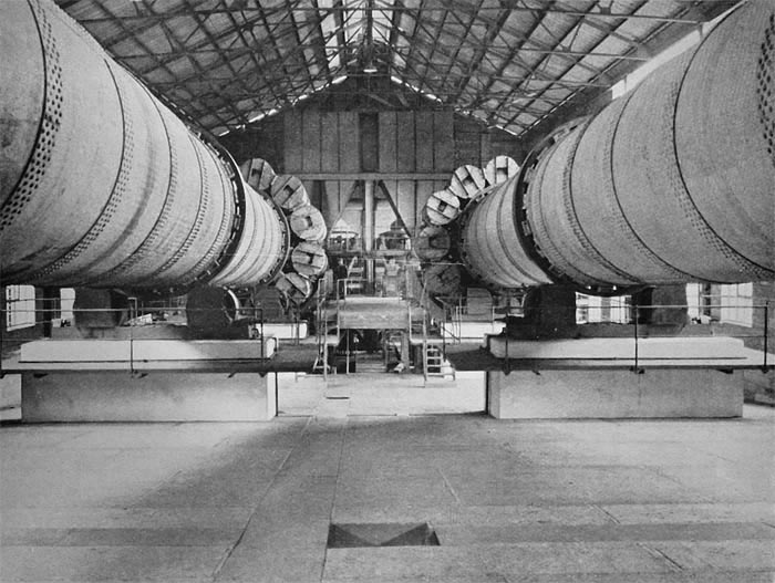 Figure 3. Kilns - view towards front end.
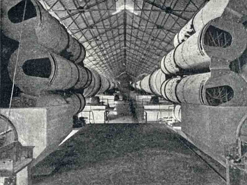 Figure 4. Kilns and coolers from the firing floor.
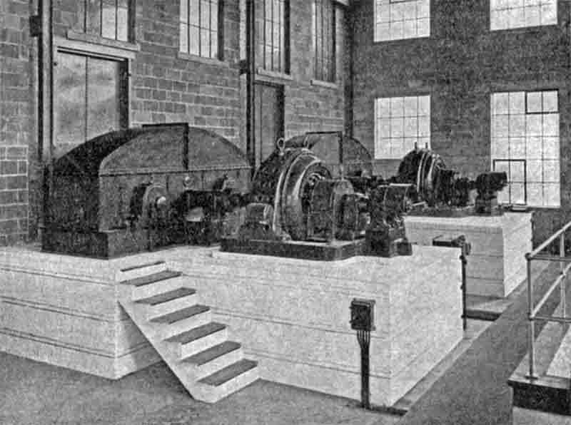 Figure 8. 650 HP motors and Symetro gear boxes for the two rawmills.
Two kilns are housed in the kiln building, which also accommodates the coal grinding mills. The kilns are 276 ft. long by 8 ft. 4½ in. diameter with enlarged burning zones 46 ft. long by 10 ft. 4 in. diameter (Note 7), each having a rated capacity of about 10 tons of clinker per hour. The coolers are of the latest design, comprising twelve integral coolers arranged around the periphery of the kiln itself. These coolers are fitted with a large number of hanging chains which, as the kiln rotates, alternately become buried in the clinker and acquire part of the clinker heat in order to give it out again to the ingoing cold air when the movement of the kiln raises them from the hot clinker.
From the kilns the clinker drops on to a belt conveyor made of special fabric and designed to withstand hot temperatures. This conveyor carries the clinker into a small pit which is emptied at frequent intervals by means of an overhead crane and grab which dumps the clinker into a store having a capacity of 3,350 tons at floor level (Note 8).
In the kiln house building behind the burner's platform is situated the coal-grinding plant. This consists of combination ball and tube mills through which hot air from the clinker coolers passes, thus combining the operation of drying and grinding and dispensing with the necessity for a coal drier (Note 9). The coal is recovered from the hot air by means of a cyclone and elevated to fine coal storage bins, thus enabling the coal mills to be shut down at intervals for repairs and also enabling them to be run at full output when the kiln consumption is less than the mill capacity.
Coal is received at the works sidings in railway wagons which are run on to a tippler from whence the coal is elevated to reinforced concrete coal silos at the rate of 120 tons per hour. The same tippler is also used for discharging gypsum in bulk, a by-pass conveyor being provided for this purpose.
Grinding
The grinding department of this works is a spacious building combining both the raw and clinker grinding mills. The building is divided by a partition, on one side of which are the high and low tension switchboards together with the reduction gears and motors, which are fitted to all the mills. A slow-speed shaft for each mill projects in through the wall into the grinding room proper, in which are also placed the pumps for transporting both the slurry and the finished cement (Note 10).
Cement Mills
These mills (two in number) are similar to the raw mills of 36 ft. length and 7 ft. 2½ in. diameter, but are fitted with 750-HP auto-synchronous motors working at 3,000 volts. From the cement mills the cement is transported to storage by a pneumatic system through a pipeline 336 ft. long and 4 in. in diameter (Note 11). The vertical height to which the cement is elevated through this pipe to the silo is 73 ft. 9 in., and four rotary compressors, each having a cubic capacity of 525 ft. at 40 lbs. pressure, provide the necessary power for the system.
The cement from the mills runs into one or other of two tanks fitted with a float valve which is operated by the level of the cement in the tank. The release of this valve admits air into the tank, which causes the cement to be projected into storage; meanwhile the other tank is being filled in similar manner.
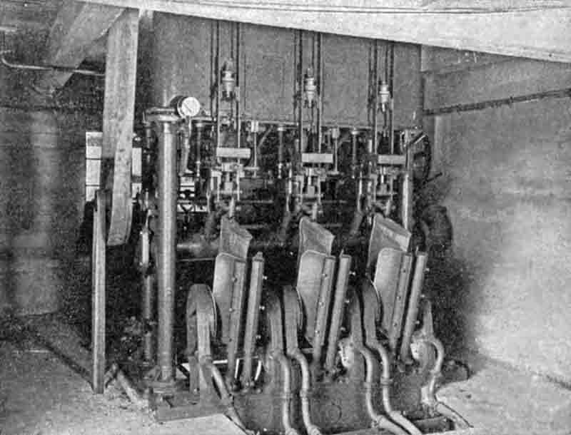 Figure 10. 3-spout Fluxo packer.
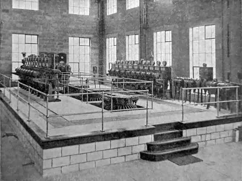 Figure 9. Main switchboard and 3 / 4 kV Transformers.
Cement Storage
Six reinforced concrete silos, each of 1,500 tons capacity, are provided, one being divided into compartments for special grades of cement in small lots. Packing is done automatically, involving the use of valved bags. These bags are hung on the delivery spout of the weighing machine, and when the correct weight of cement flows into them they are automatically discharged from the machine and fall down a chute ready for loading into railway or road vehicles. Above the weighing machines is a special cement storage hopper fitted with mixer arms after the manner of a slurry mixer. A slight and continuous injection of compressed air to the hopper renders the cement of a fluid nature and enables it to flow freely by gravity into the bags.
Power Supply
For the purpose of providing power to the factory the supply area of the Yorkshire Electric Power Co., Ltd., was extended by the Electricity Commissioners into Derbyshire, to include the village of Hope (Note 12). An overhead ring line working at 33,000-volts pressure has been extended from the neighbourhood of Sheffield, and in the event of failure on one line the alternative route could be used to maintain the power supply. Motors exceeding 150 HP are run at 3,000 volts, while 400-volts pressure is available for motors of 150 HP and less. The distribution of the power is accomplished through the medium of four sub-stations. At sub-station "A" two 3,000-kVA transformers and switchgear are provided with facilities for extension to 9,000 kVA. In this sub-station the pressure is stepped down from 33 kV to 3 kV and the lay-out provides for the supply of power and lighting current to the district generally.
Sub-station "B" contains the two metering boards (one the property of the Power Company and the other the property of Messrs. G. & T. Earle, Ltd.) on which are fitted recording instruments to provide a continuous record of units consumed as well as a kVA meter which records the maximum demand in kilovolt-amperes. This instrument comprises a watt-hour meter and a reactive component meter mounted in the same case and coupled together by a special system of gearing in such a manner that a true integration of kilovolt-ampere hours is obtained. This meter is guaranteed accurate at all power factors from unity to zero, both leading and lagging.
Maximum demand is ascertained on the Power Company's panel by means of a thermal type indicator. In this instrument the ingoing supply is utilized to heat the air in a differential thermometer tube. The consequent expansion of the air in the bulb pushes a liquid over into a reading tube provided with an indicating scale. The amount of liquid so displaced remains in the reading tube and represents the maximum demand until the instrument is re-set.
In addition, this sub-station provides for the distribution of the power with appropriate switches to all parts of the works, and transformers stepping down to 400 volts for the smaller motors and 230 volts for lighting are here provided.
There is a further subdivision from sub-station "B" into stations "C" and "D", the former of which is situated near the quarry and provides power for the excavator, air compressor and well drills as well as for a motor generator which converts the 3-phase supply to 250 volts DC for use on the electric locomotives engaged in hauling the rock from the quarry face to the crusher house. Sub-station "D" is situated in the clayfield and provides power for the washmill, slurry pump and motor supply.
The works generally have been built in a substantial manner with concrete blocks made of local limestone and cement from the factory of Messrs. G. and T. Earle, Ltd., at Wilmington, and a pleasing grey colour in harmony with the surroundings is obtained. The office block contains the chemical laboratory and testing rooms as well as provision for the Works Manager and his staff, while a visitors' dining room and garage adjoin. All buildings are of fireproof construction and practically no woodwork, other than furniture, is to be seen in the factory. With minor exceptions the works have been planned throughout and the machinery and buildings erected by Messrs. G. & T. Earle's own staff.
The electric navvy is by Ruston & Hornsby, Ltd.; electric locomotives by Metropolitan-Vickers, Ltd.; jaw crusher and clay washmills by Vickers-Armstrongs, Ltd.; gyratory crusher by Symon Bros.; combination mills, pneumatic cement transport, kilns, and bag-packing by F. L. Smidth and Co., Ltd.; motors for combination mills by Crompton-Parkinson, Ltd.; slurry screen by Sunderland Forge & Engineering Co., Ltd.; dust-collecting fans by Keith, Blackman & Co. (Note 13); coal-wagon tippler by Mitchell Conveyor and Transport Co., Ltd.; electrical apparatus and instruments by Geo. Ellison, Ltd., Metropolitan-Vickers, Ltd., Reyrolle & Co., Ltd., Crompton-Parkinson, Ltd., and Nalder Bros. & Thompson, Ltd.; underground cables by British Insulated & Helsby Cables, Ltd., and MacIntosh Cable Works Co.; drag-line scraper by Mr. E. F. Sargeant.