In May 1963, an account of a visit to the Drogheda plant was published in Cement, Lime and Gravel (pp 143-151). Many of the illustrations to the article now reside in the British Geological Survey GeoScenic FLS plants in general. The plant closely paralleled contemporary developments at Aalborg and West Thurrock . All the pictures can be viewed in higher definition at the GeoScenic website.
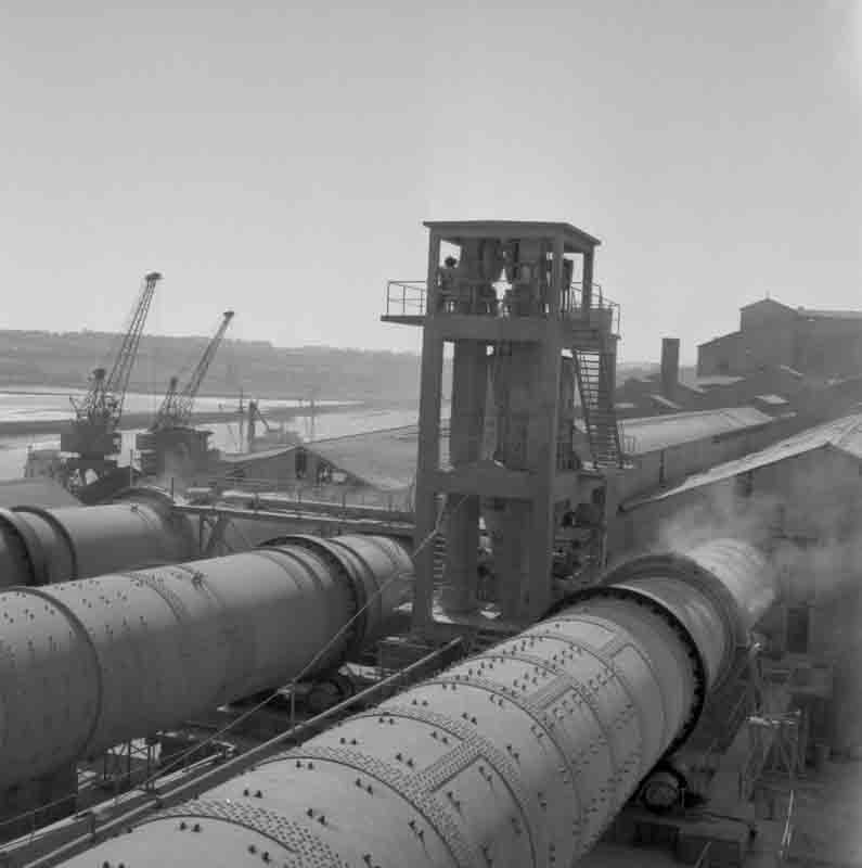
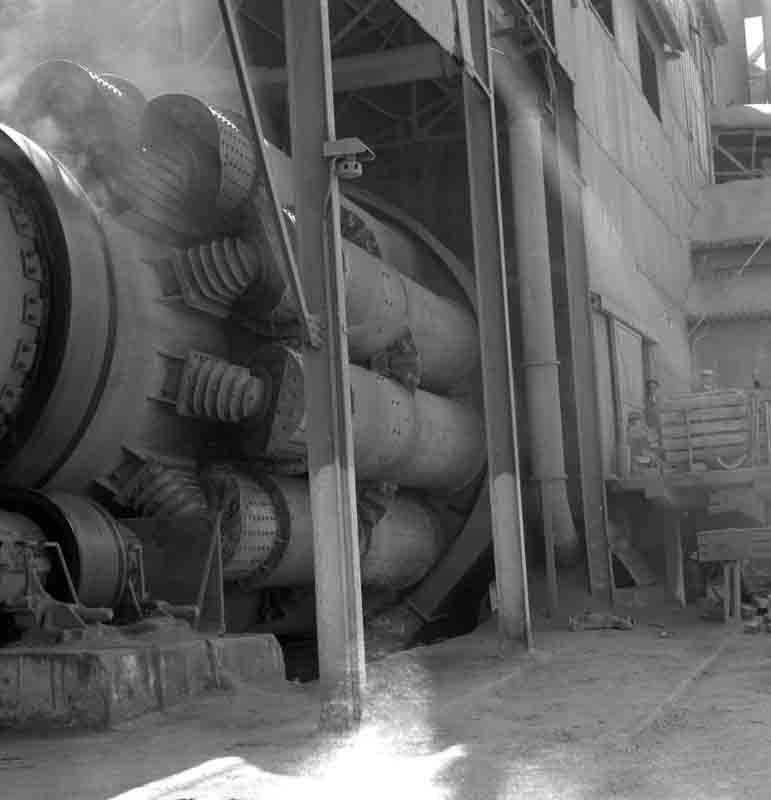
Picture ©NERC, GeoScenic Cat No. P539927. This shows the kilns viewed SW from the slurry feeder floor in 1963. The three otherwise similar kilns show the progress in shell construction; to the right, No. 1 (1938) is entirely riveted. No. 2 (1941) is partially welded, and to the left, No. 3 (1954) is entirely welded. In the centre is the tower, with elevator and silo, for feeding dust back to the three kilns through scoops downhill from the chains. A similar tower was installed for West Thurrock kilns 7 and 8. A certain amount of dust leaks from the seals of the return port hoods. Attachments for festoon chains can be seen extending to near the end of the expanded cold end of the kiln - the rest contained refractory crosses. The kilns all had diameters of 3.6 m at the cold end, 3.3 m in the middle and 3.6 m in the burning zone. Kilns 1 & 2 were 129 m long and Kiln 3 was 136 m long. The wharf and River Boyne are off to the left.
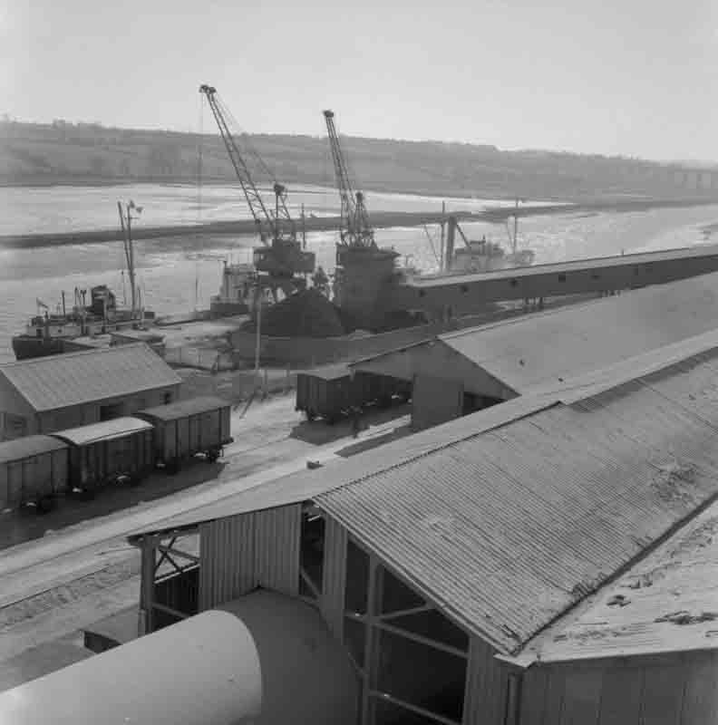
Picture ©NERC, GeoScenic Cat No. P539925. This shows the wharf, viewed SW from the dust return tower. The wharf could accommodate small coasters for import of coal and distribution of cement and clinker. Larger vessels could not reach the wharf because of the bar at the mouth of the Boyne. The ascending conveyor took coal to the fuel silos. Rail loading sidings ran parallel to the wharf. Kiln 3 is in the foreground.
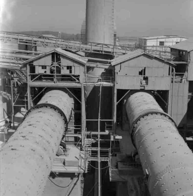
Picture ©NERC, GeoScenic Cat No. P539926. This shows the inlet ends of kilns 1 (left) and 2, viewed eastward from the top of the dust return silo. The tail of the kiln has a reduced-diameter section carrying the back-end seal, and discharges into an exhaust chamber not much wider than the kiln. The individual roofed slurry feeder houses are very characteristic. The kilns were 35 ft apart.
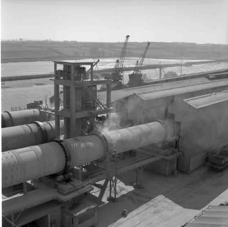
Picture ©NERC, GeoScenic Cat No. P539929. This gives another view of the kilns, SE from the top of the slurry blending silos. Compared with many other Unax kilns, these were mounted fairly high up.
Picture ©NERC, GeoScenic Cat No. P539948. This shows No. 1 kiln Unax planetary cooler. An underground conveyor running to the right took all three kilns' clinker to a pit in the crane store. The cantilevered cooler is of a 1950s design and may have been retrofitted.
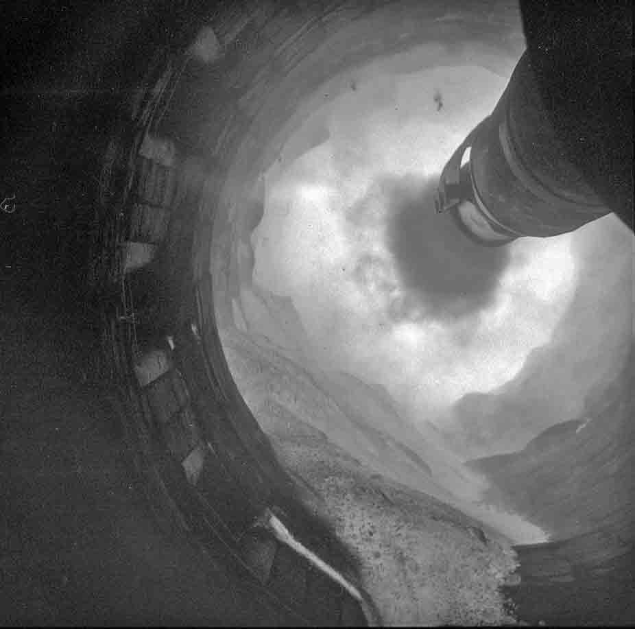
Picture ©NERC, GeoScenic Cat No. P539945. This shows the burning zone interior, probably of No. 1 kiln, rotating clockwise. The inlet ports of the cooler can be seen on the left. The hot clinker was held back by a refractory dam ring about 5 inches high, and the firing pipe extended far enough to maintain the burning zone some distance up the kiln, thus protecting the sensitive cooler ports from material at maximum temperature.
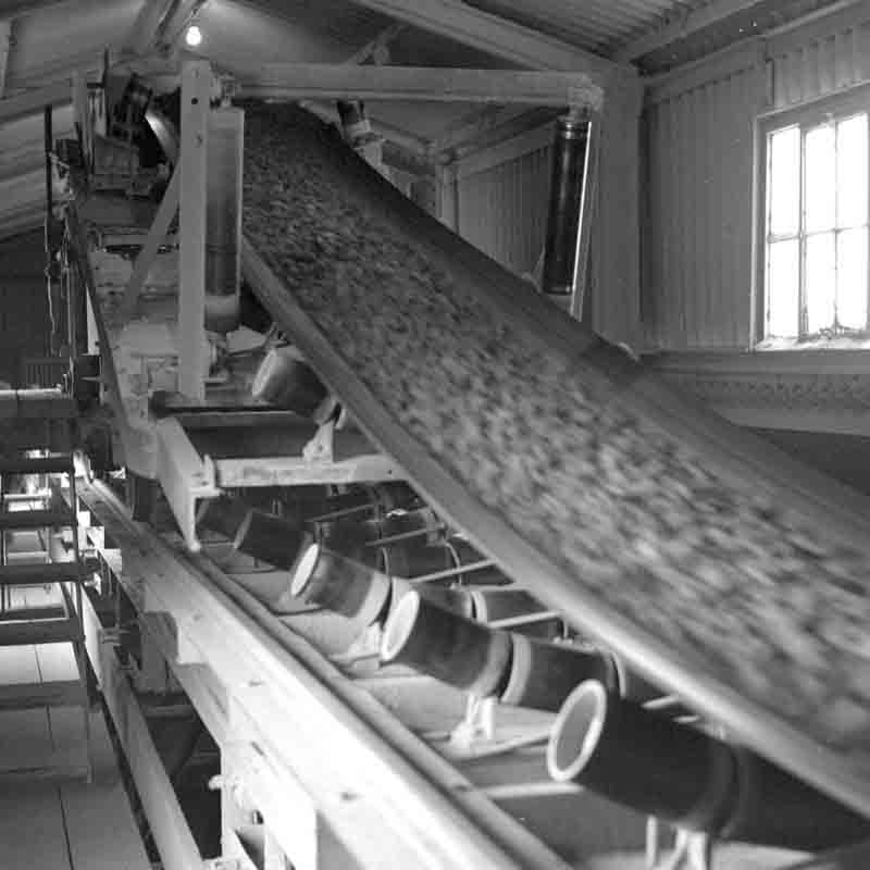
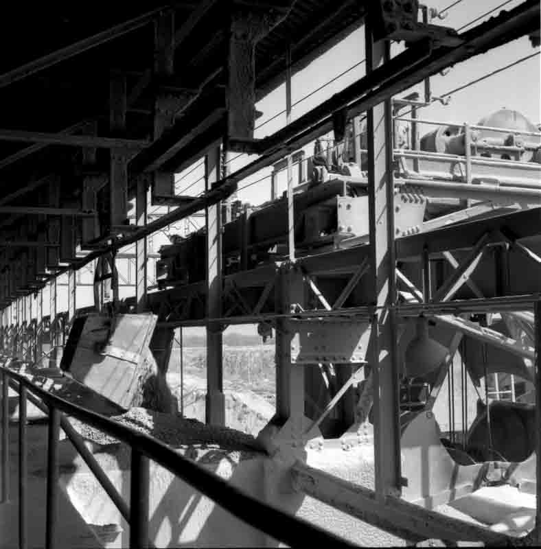
Picture ©NERC, GeoScenic Cat No. P539949. This is a tripper on what is probably the coal belt. The belt runs from the feed hopper on the wharf to the crane store, but coal could also be diverted into any of the three kiln raw coal bunkers by this moveable tripper. Although in operation, the plant was in the process of changing to oil firing.
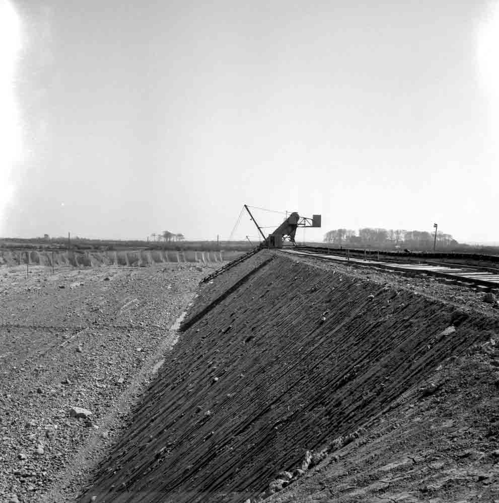
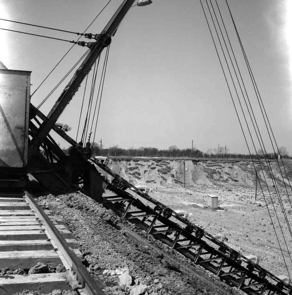
Picture ©NERC, GeoScenic Cat No. P539959. This shows the Togher clay field, looking ESE, and one of two O & K multi-bucket excavators. These extracted clay in 5 ft wide tranches along a face up to 400 m long.
Picture ©NERC, GeoScenic Cat No. P539958. This is a close-up of the MBE, looking west.
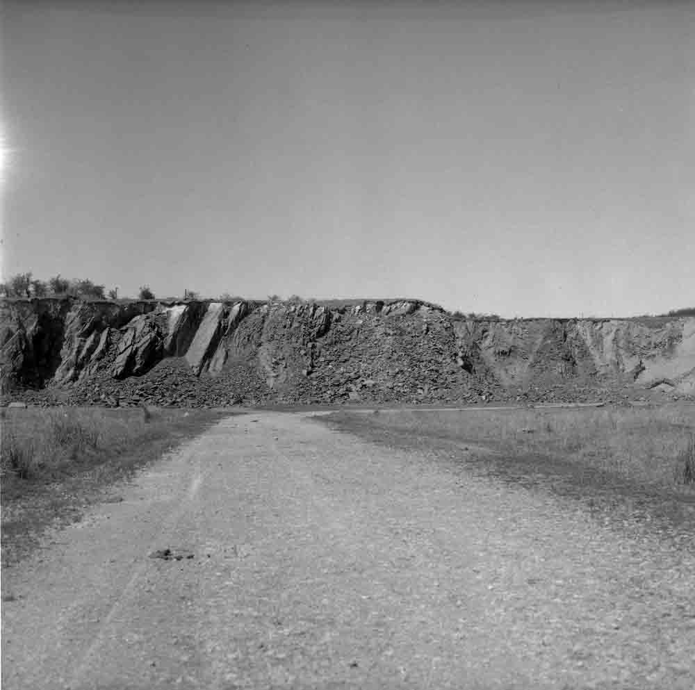
Picture ©NERC, GeoScenic Cat No. P539960. The shale quarry, looking west. At the time the shale was only used in small quantities, and was quarried for a few weeks in the year..
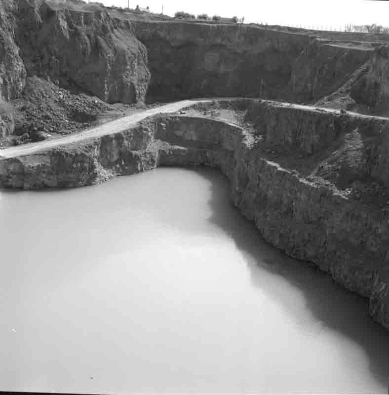
Picture ©NERC, GeoScenic Cat No. P539968. This shows the worked out eastern corner of the limestone quarry.
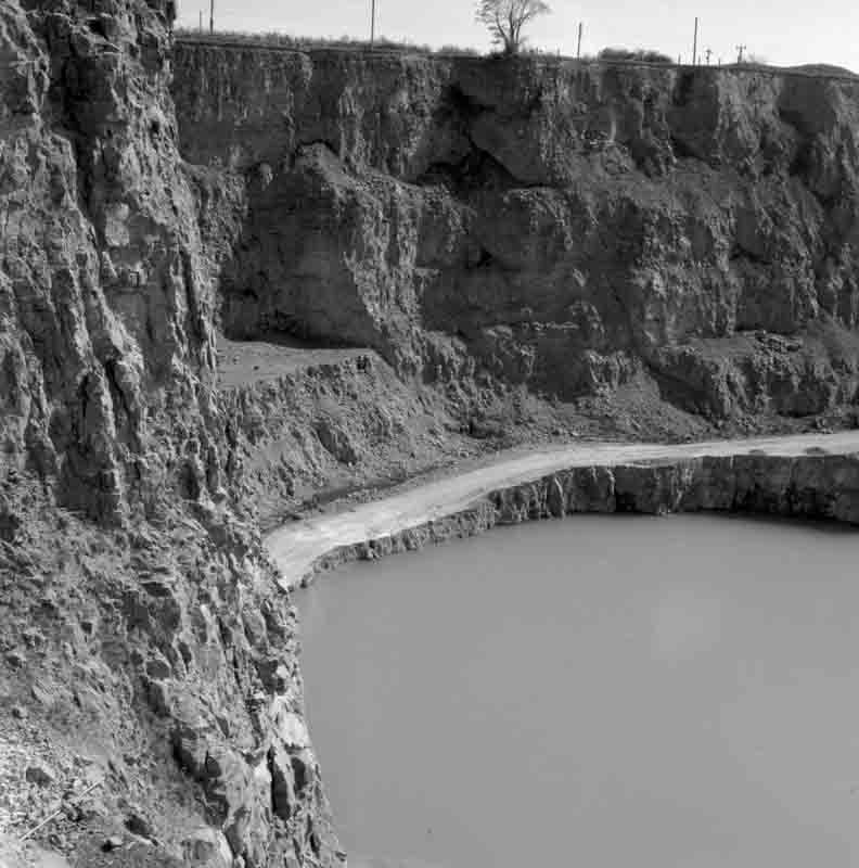
Picture ©NERC, GeoScenic Cat No. P539969. This shows another worked out corner of the limestone quarry.
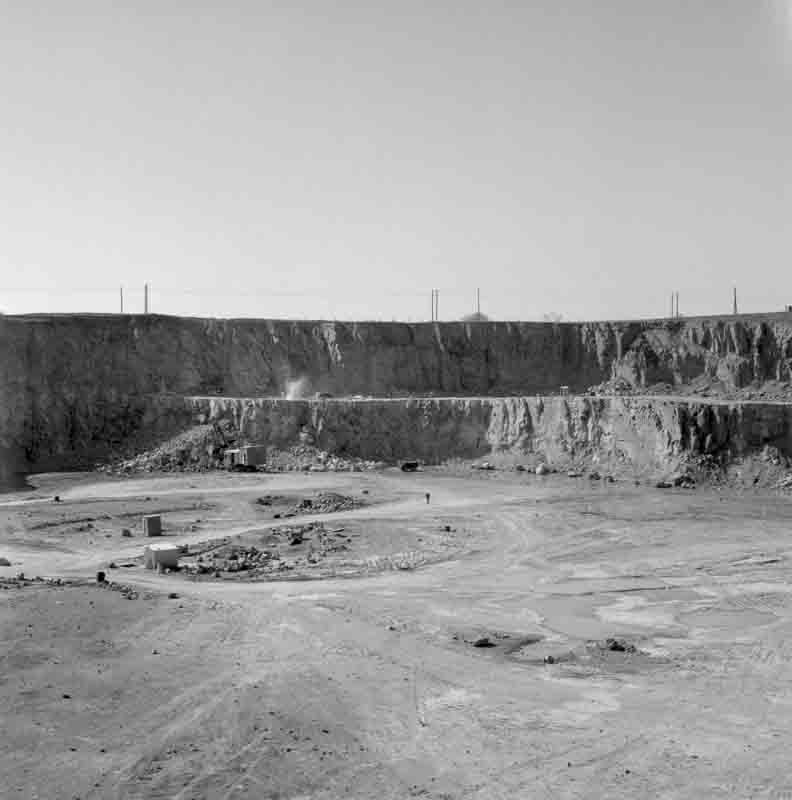
Picture ©NERC, GeoScenic Cat No. P539967. This shows the southwestern part of the quarry in active use. The middle bench is being drilled and the excavator is picking up stone from the previous blast. The benches were each about 15.5 m high. Further down, the material was progressively more argillaceous.
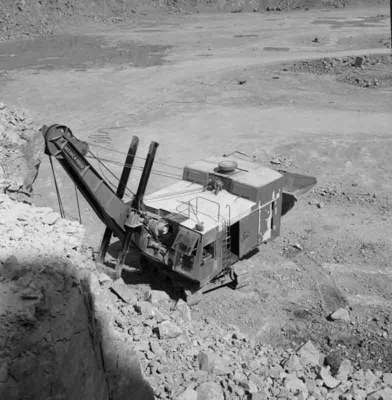
Picture ©NERC, GeoScenic Cat No. P539966. One of two Menck excavators picking up blasted limestone on the lower bench.
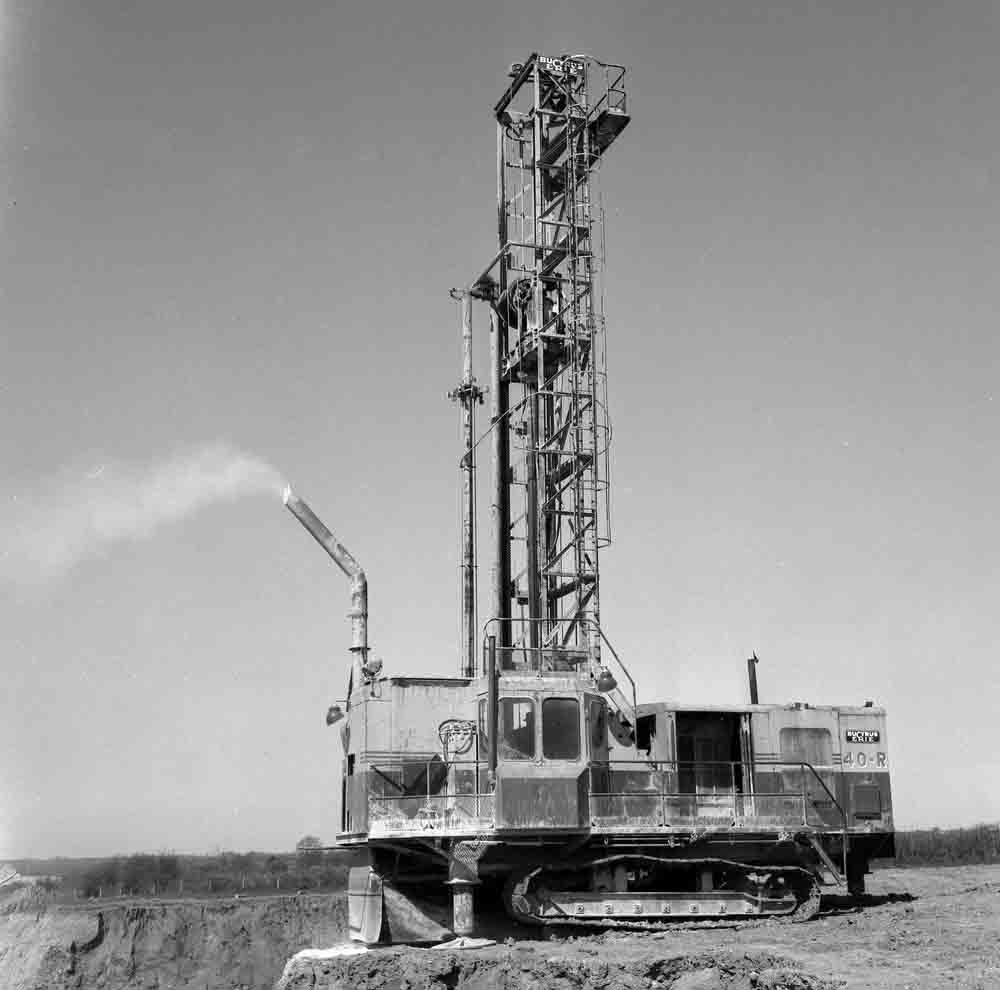
Picture ©NERC, GeoScenic Cat No. P539965. This shows the Bucyrus Erie 40-R drill drilling the upper bench
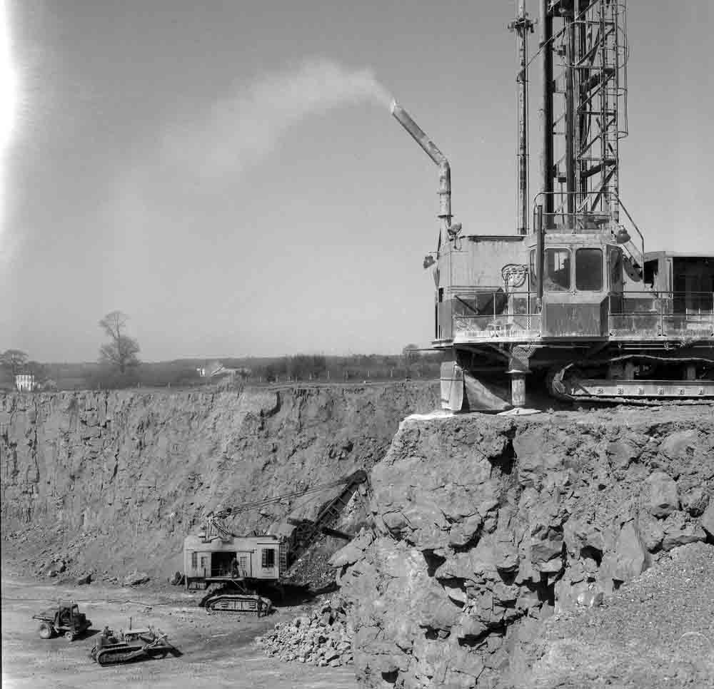
Picture ©NERC, GeoScenic Cat No. P539964. The Bucyrus Erie 40-R drill and Ruston Bucyrus face shovel working the upper limestone bench.
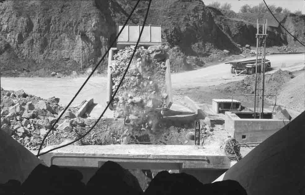
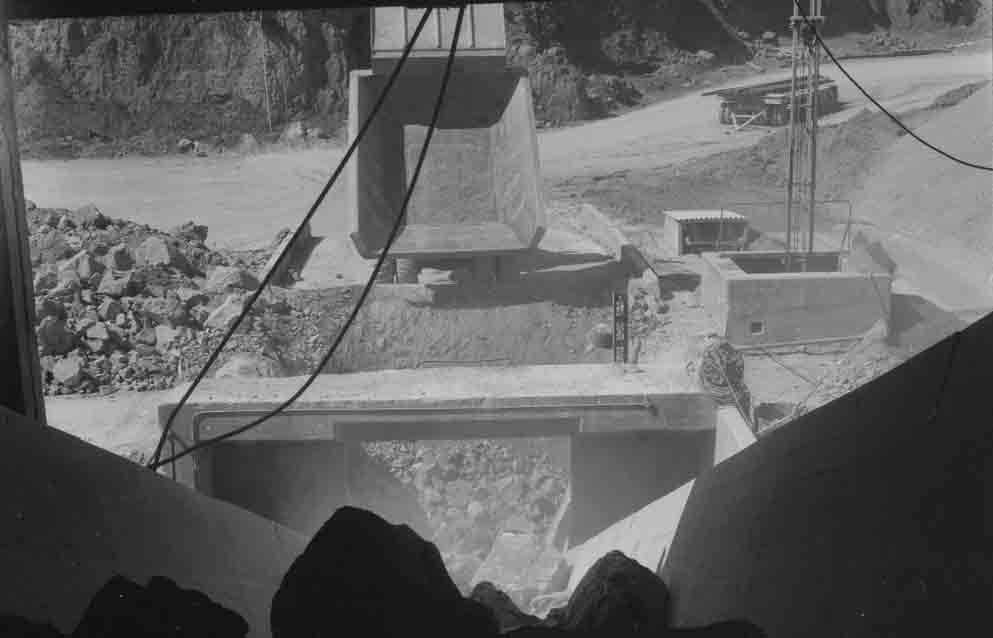
Picture ©NERC, GeoScenic Cat No. P539963. A dump truck tipping limestone into the apron feeder of the primary crusher.
Picture ©NERC, GeoScenic Cat No. P539962. A dump truck tipping limestone into the apron feeder of the primary crusher.
Picture ©NERC, GeoScenic Cat No. P539953. Grizzly feeder above the primary limestone crusher: an FLS 1.5 × 1.2 m jaw crusher of 150 kW producing 225 t/h of -200 mm stone. This was followed by a secondary crusher (not pictured): an FLS 260 kW double rotor impact breaker, each rotor 1.5 × 1.25 m diameter, yielding -40 mm stone. The product was elevated to two 200 t silos.
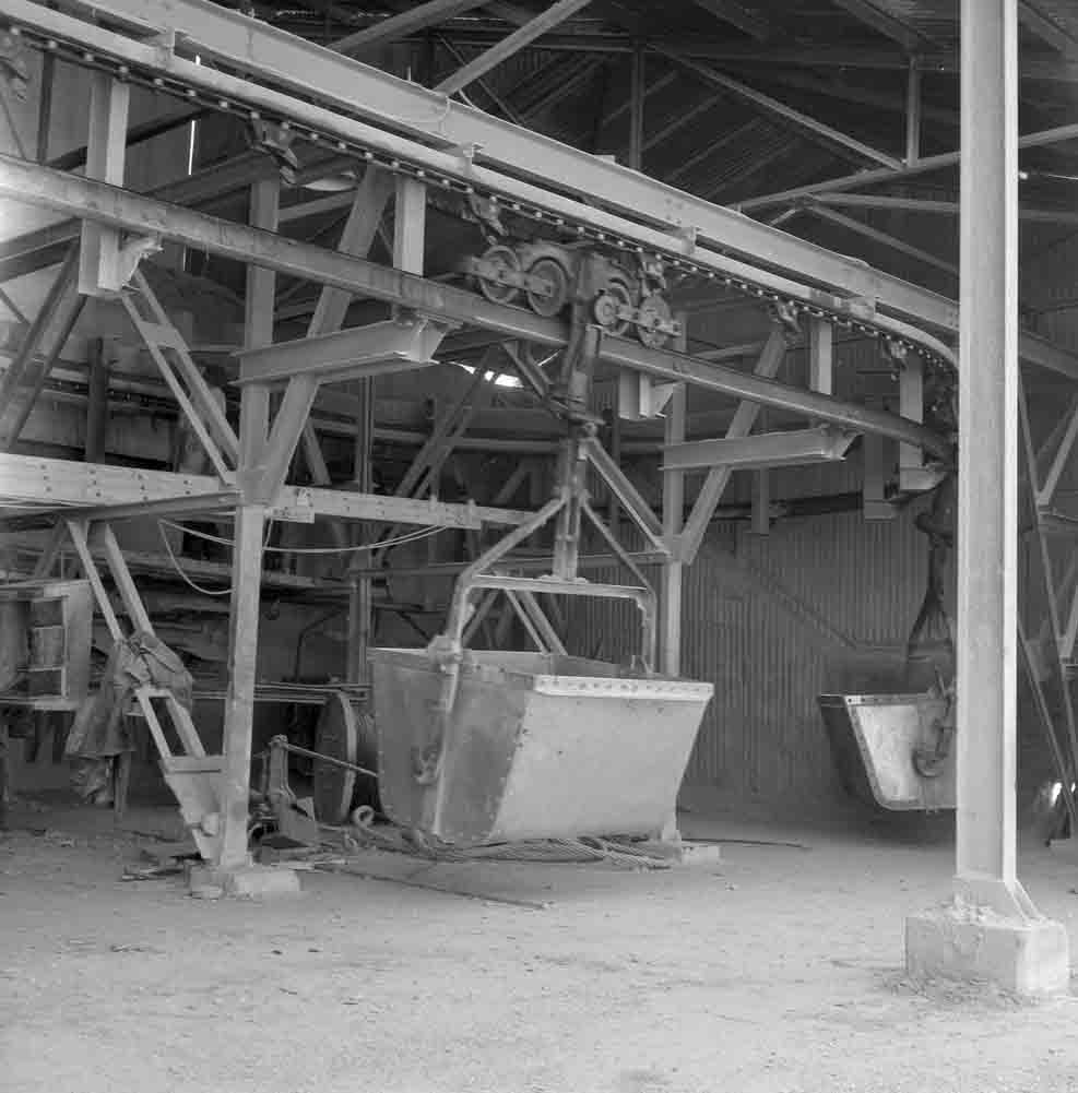
Picture ©NERC, GeoScenic Cat No. P539961. The loading end of the limestone ropeway. This had 170 buckets of 1.25 t capacity each, and completed the journey to the plant in 31 minutes, moving 2650 t/d.
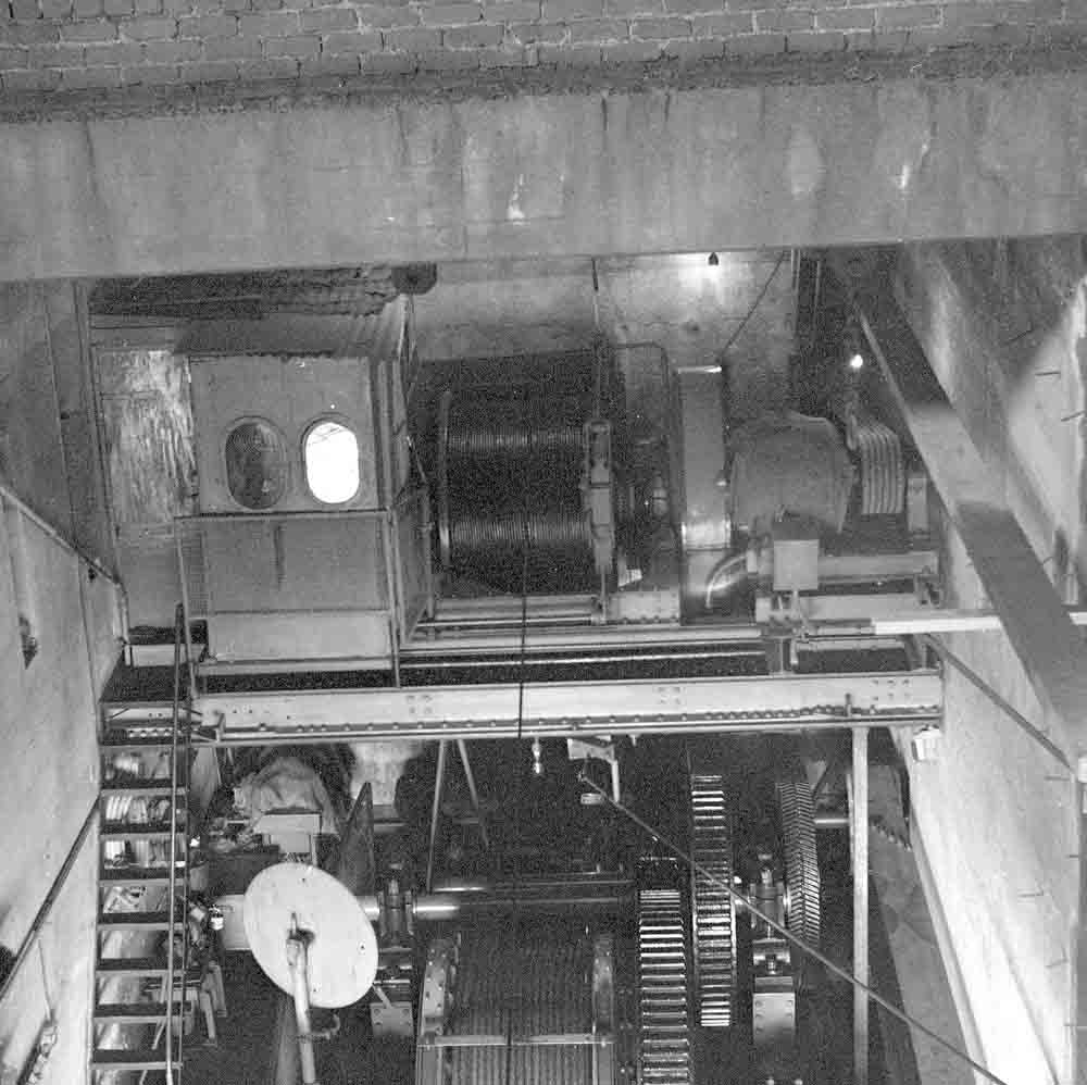
Picture ©NERC, GeoScenic Cat No. P539950. The limestone ropeway drive gear.
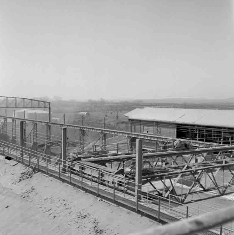
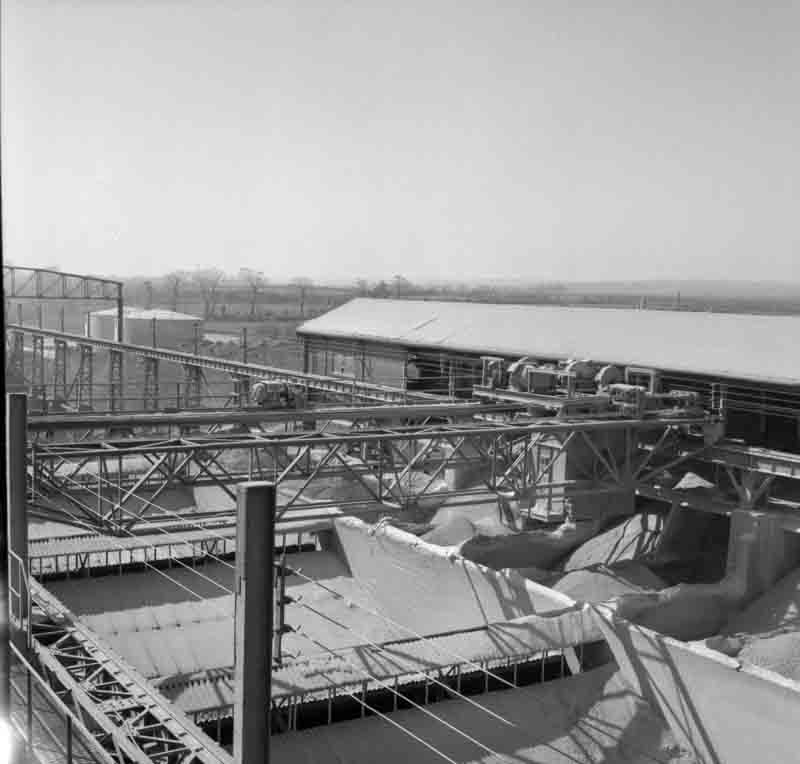
Picture ©NERC, GeoScenic Cat No. P539935. Discharge end of the limestone ropeway, over the rawmill feed hoppers, with the open-air crane store to the right.
Picture ©NERC, GeoScenic Cat No. P539928. The open-air crane store, looking NW. On the far side is the housing of the ropeway discharge trippers. On the left are the fuel oil tanks used by the plant during the 1960s, although the use of oil is not mentioned here, and coal was in use.
Picture ©NERC, GeoScenic Cat No. P539930. Another view of the crane store.
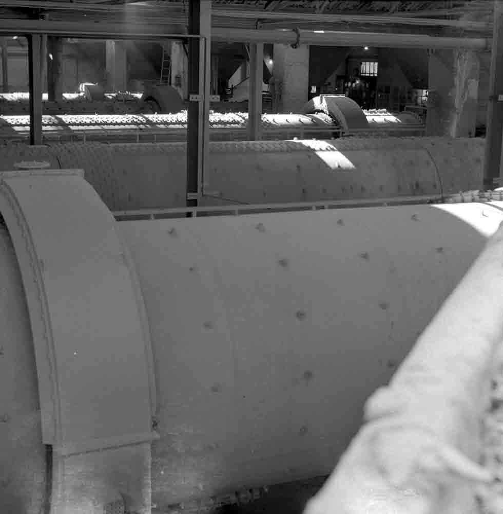
Picture ©NERC, GeoScenic Cat No. P539951. The mill house, looking west. Raw- and finish-mills were side by side. The mills visible are (nearest to furthest) RM2, RM1, FM1, FM2, and FM3. As with Kiln 1, the 1938 mills were both of riveted construction.
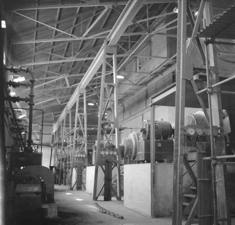
Picture ©NERC, GeoScenic Cat No. P539933. The mill motor room, looking west. The 6 mills all had 1000 kW motors and were driven through Symetro gearboxes and Cardan shafts.
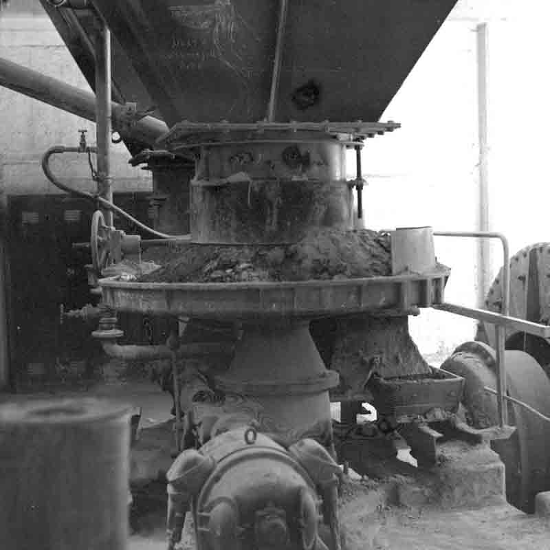
Picture ©NERC, GeoScenic Cat No. P539954. Limestone feed table on No. 3 rawmill. The table behind delivered shale, the large sloping pipe delivered clay slurry, and the smaller pipes delivered water.
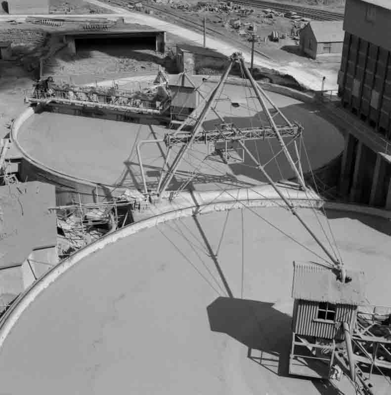
Picture ©NERC, GeoScenic Cat No. P539932. The two 30 m kiln feed basins. These each had an active volume of 3800 m3 , holding 3862 t of dry raw material, equivalent to 2414 t clinker. Together, when full, they could provide a rather parsimonious 3-days' kiln run. It was FLS practice to distribute incoming slurry across the radius of these large basins via the agitation boom, hence the elaborate overhead pipework. These basins are still (2019) in use.
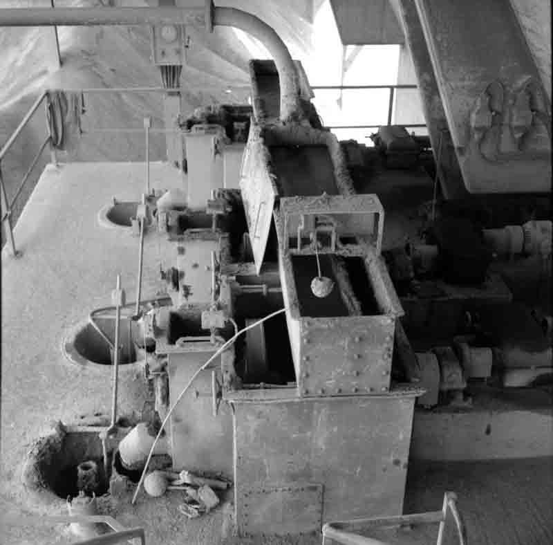
Picture ©NERC, GeoScenic Cat No. P539934. All three kiln slurry spoon feeders arranged together.
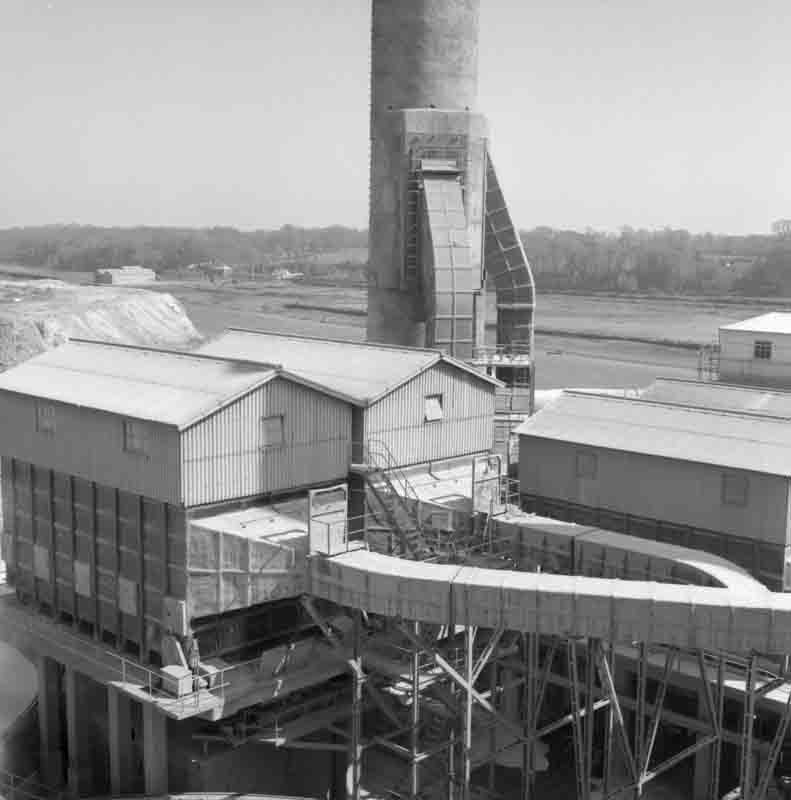
Picture ©NERC, GeoScenic Cat No. P539931. Kiln dust precipitators and stack, viewed from the slurry blending tanks. Kiln 1 (1938) originally had no dust arrestment. Parallel Lodge Cottrell precipitators were fitted in 1940, behind the original stack, hence their position. All three operated under pressure. The dust collected was returned to the kilns via scoops.
Original content © Dylan Moore 2017: commenced 30/12/2019: last edit 28/02/2020.Return to List
