Plans of buildings at the cement works of the Hartlepools Cement Company, Ltd.
This tiny early 20th century plant is unusual in that construction plans still exist, which convey an idea of the details thought important in the construction of a compact chamber kiln plant. The plans are held at Teesside Archive, and I was made aware of them by Alan Betteney. They were prepared for Messrs. Booth & Bolton of West Hartlepool, and dated 10/4/1899.
The following drawings have been prepared based on the dimensions given on the plans, and not on the actual drawings, which are not of high quality, and contain a number of significant errors. They represent the original plans of 1899, and the mill buildings finally constructed were significantly different.
Chamber kilns

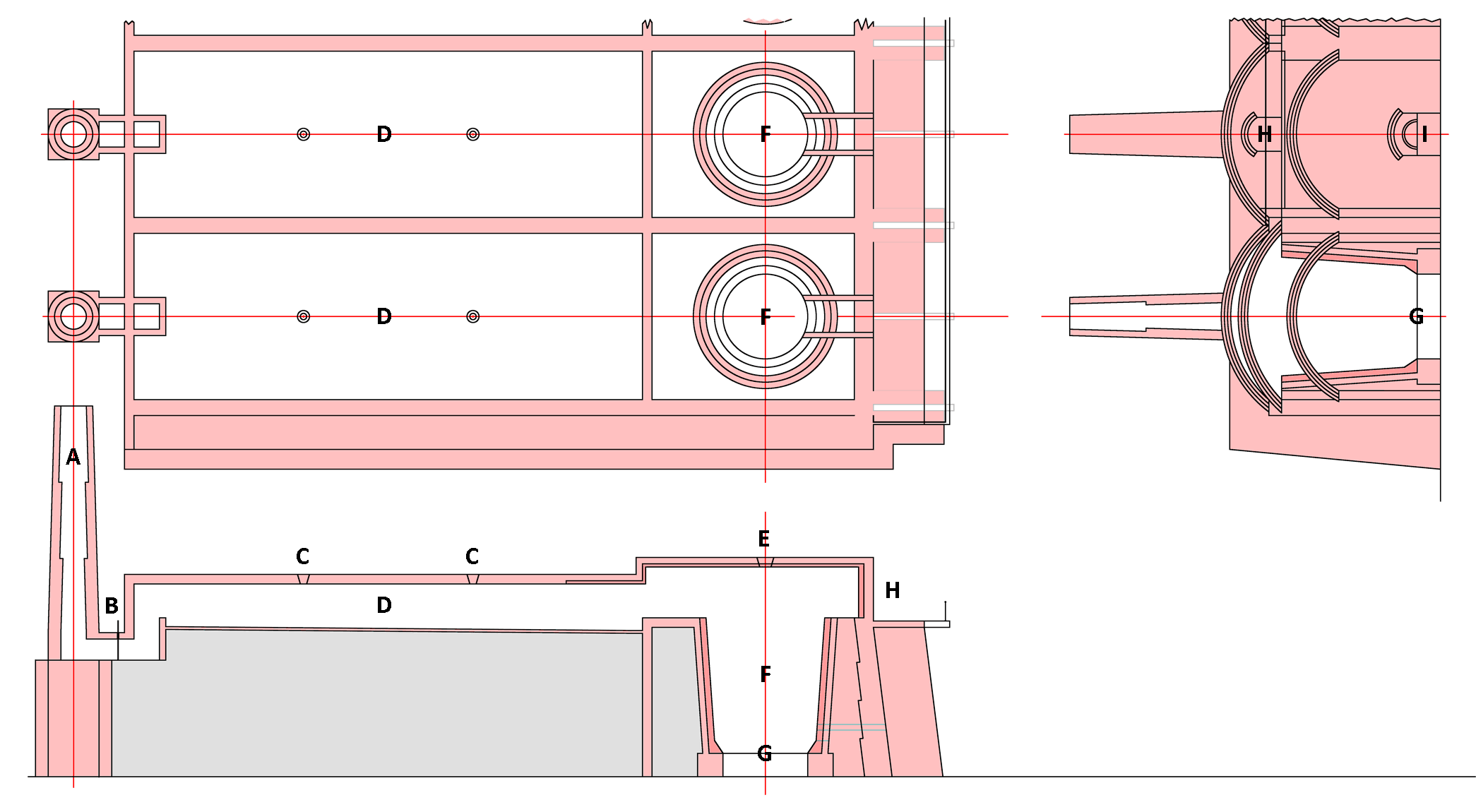
The original proposal was for eight kilns, but only five were finally built. Each kiln had its own stack A, 30 ft high and with internal diameter 3 ft, built on top of a solid concrete footing. The drying chamber D was connected to the stack by a short duct with a guillotine damper B to control airflow. This was opened up while lighting the kiln to promote ignition, then throttled down progressively to slow the burning rate to ensure that the slurry dried thoroughly. The drying chamber D was 60 ft long, 19 ft 7½ in wide, and 18 in deep at the hot end, and roofed with an arch of 13½ inch brickwork. The chamber floor sloped by 6 inches towards the hot end, so the cold end depth was only 12 in, in order to present a thinner layer of slurry to the cooler gases at the cold end. Chambers on flat ground were often supported on masonry arches, but here they were on "slag or earth filling". The chamber was filled from pipe manifolds through the filling ports C. After drying to around 3% moisture, the raw material was dug out (note: the maximum headroom in the empty chamber was only 5 ft 6 in), the "slip" was broken into brick-sized pieces and loaded into the kiln. Wood kindling was first placed on the fire bars G, followed by a substantial layer of coke. Slip was normally added by placing a plank over the kiln, wheeling a barrow full of slip across and tipping it into the kiln F, as directed by the burner standing below.
The kiln was 16 ft deep from the brim to the fire bars, 14 ft in diameter at the top, tapering to 12 ft at the bottom, with a hearth of diameter 10 ft. It had a 9 in masonry structural shell, with a 9 in firebrick lining inside. A layer of coke was placed on top of each layer of slip, the ratio of coke to slip being carefully varied both vertically and radially to obtain as even a burn as possible. The coke was fed in through the loading door H. When filled, the chamber was re-filled with slurry, the kiln was lit, and the loading gang moved on to the next kiln. The burner could make only minor adjustments to the draught during the two or three days that the kiln took to burn out. The kiln was then put on full draught to cool down, after which the clinker, still red-hot in parts, was raked out through the unloading door I (again, maximum headroom 5 ft 6 in).
The dimensions here are atypical. Johnson's chambers were typically 100 ft long. These chambers were undoubtedly too short. To make the 25 tons of clinker claimed for these kilns, 39 tons of dry raw material would be needed. This amount, in a slurry with 40% moisture content, would occupy 1452 cubic feet, which entails filling the chamber virtually to the brim - i.e. 18 inches deep at the hot end and 12 inches deep at the cold end. The recommended depths for Johnson's kilns were 12-15 inches and 3-4 inches respectively. The volume of the kiln from fire-bar to brim is 2071 cubic feet.
Mill building

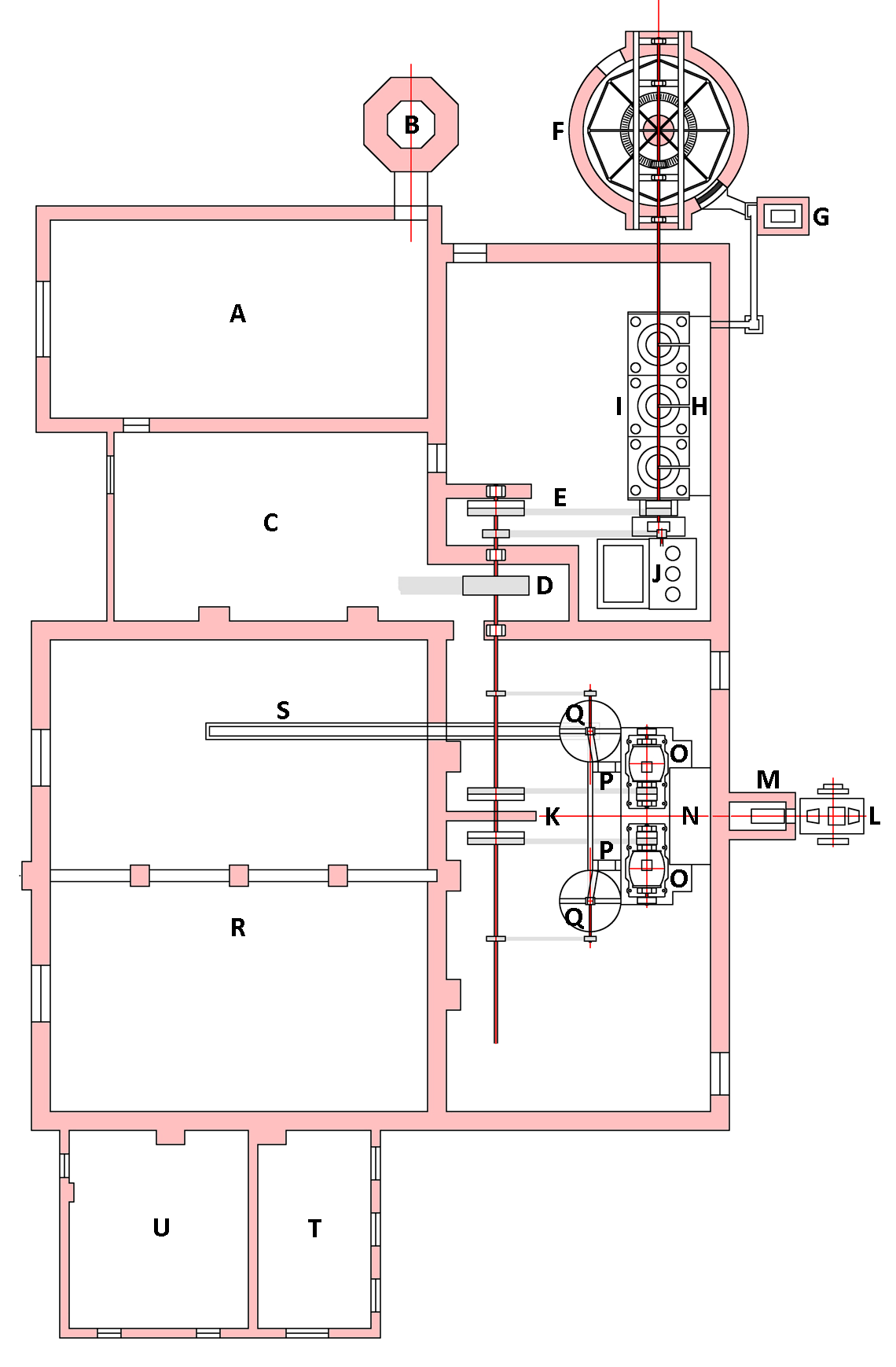
The millhouse contained the grinding equipment for raw- and finish-grinding, all driven by a single steam engine. At least two boilers in the boiler room A were exhausted to stack B. The actual stack was square in section. The steam engine - presumably of horizontal form, was in room C, with its flywheel connected by belt or ropes to the main layshaft drive wheel D. This layshaft drove everything. The raw mills were driven from fast and loose belt E to a shaft turning both the washmill F and the flat stone mills I. The washmill was fed, probably by wheelbarrow, on the NW side, and slurry emerged through the grid on the SE, descending into the boot of elevator G. This discharged down a flume into holding tank H, from which the three flat stone mills were fed. The mills were 4 ft 3 in diameter according to the drawing, which was fairly typical. The fine slurry product descended to the sump of the three-throw pump J which tranferred the slurry to the selected kiln chamber. There is no slurry storage, so it is clear that the rawmills were run on an "on-demand" basis, whenever a chamber needed filling. It was therefore necessary for the slurry composition to be correct at all times. It is not clear how this was achieved (and in fact it probably wasn't).
The main layshaft also drove the finish mills, from fast and loose wheels K. Clinker unloaded from the kilns were transferred by wheelbarrow or rail skip to a sunken jaw crusher L discharging into elevator M which delivered the crushed clinker (say 5 mm down) to the feed hopper N. This fed two Askham mills (or similar) O. Each mill discharged to its own elevator P which lifted the product to an Askham separator Q. The oversize material from this was returned to the mill, and the fines were transferred to the store R by conveyor S. The laboratory T and the sack store U were not here in the final arrangement. They may have been in the SE extension of the buildings.
Workshops

The insubstantially-built workshop range was built against the western property boundary, and consisted of:
A Blacksmith's shop, complete with forge
B Fitting shop
C Cement store, perhaps for packed product
D Office