Lepol preheaters are designed to be fed with nodulised damp feed, and can be applied to dry powder rawmix which has been agglomerated into nodules by addition of a small amount of water (Semi-Dry Process) or to slurry filter cake that has been formed into nodules (Semi-Wet Process).
Semi-Dry Application
The use of serious energy-efficient systems began with the semi-dry Lepol process. This was invented by Otto Lellep and his design was built and marketed by Polysius, hence the proprietary name Lepol. It was first used in Germany (Rüdersdorf, 1927), and became for a while the most common system there, but the first in Britain was Cauldon A1 as late as 1957 - and this was only justified by the specious argument that Cauldon's water supply was insufficient for a wet process.
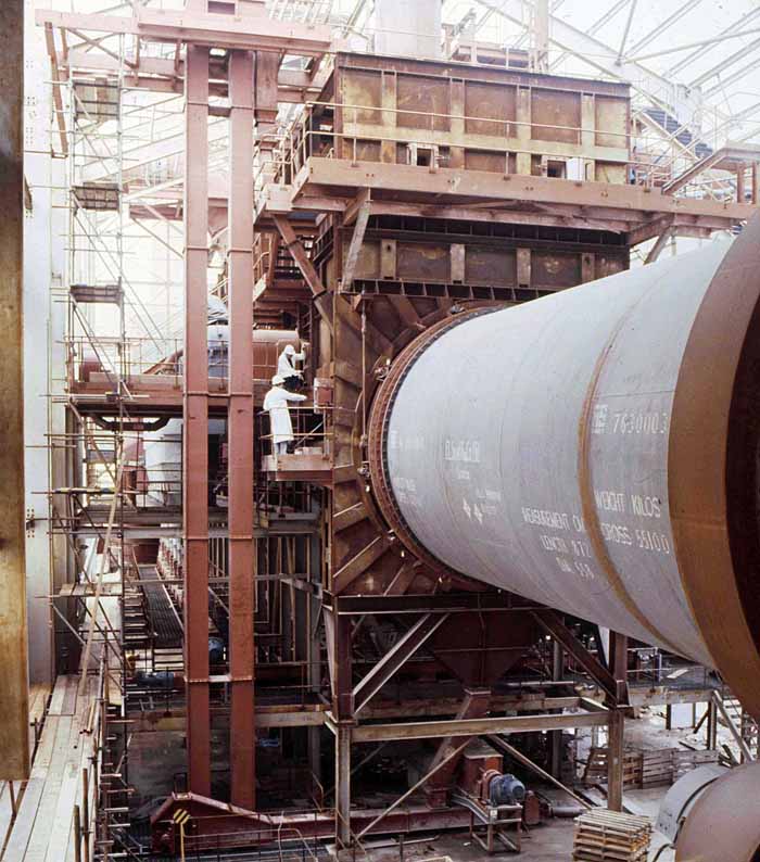
The preheaters consist of a moving flexible endless-chain grate made up of slotted steel plates which carries spherical nodules in a bed 0.15-0.3 m deep. The nodules are made from dry raw meal, by addition of 11-14% water (hence semi-dry), in a nodulizing pan. Hot exhaust gas from the kiln passes downward through the bed, the resultant cooling action protecting the grate from the hot gas. The system is potentially very efficient, and by the time they drop off the end of the grate into the kiln, the nodules are beginning to calcine. The most common pitfalls (in fact they are almost universal) are weak nodules which break up as they out-gas causing over-consolidation of the bed and reduced gas flow, and “hot blinding”, in which alkali fumes from a hot burning zone re-condense on the bed surface and again reduce gas flow. Of the Lepol kilns Cookstown A1 (installed 1969) is the least susceptible to these, and outperforms the others by a substantial margin: this is probably the only example of a Lepol kiln that could not with benefit be replaced with a suspension preheater system. All Lepols produce insufficient waste heat to dry the raw materials, and supplemental fuel (typically 0.25-0.5 MJ/kg depending on raw material moisture content) is required to heat the rawmill. Other semi-dry Lepols were installed at Dunbar, Weardale and South Ferriby. The three Cauldon and three Dunbar kilns were replaced with single precalciner kilns in 1985 and 1986, the resulting benefit being mainly in terms of simplification of the plant, allowing operation with fewer personnel. Those at South Ferriby and Cookstown remain.
Semi-Wet Application
The Lepol system also provides an efficient method for processing filter cake as a semi-wet process. Because filter cake has a higher moisture content than the semi-dry nodules (typically 17-20%), a relatively larger grate is required for a given output. In 1978, a wet process kiln at Southam (A6) was shortened and fitted with a 31.0×4.0 m Lepol grate fed with extruded filter cake. The purpose built Rochester A6 followed in 1979 with the world's second biggest grate at the time (44.0×5.6 m - second only to the 61.7×5.6 m grate at Lägerdorf, Germany - also a semi-wet process, shut down in 1996). Both these had significantly higher energy consumptions than semi-dry kilns due to the higher nodule moisture content (among other things), and the additional large power requirement of filter presses made them of marginal economic viability. In terms of output, the loadings of the grates (in tonnes per day per square metre of grate) were rather low - 4.4 for Southam and 7.7 for Rochester, compared with 9.5 for Lägerdorf. Both were shut down in 2000. Many purpose built systems were installed in Europe, particularly in France, and some still continue in operation.
Single-pass Grates
The early form of the Lepol grate as first patented was well publicised in the UK from the outset. A. C. Davis in his 1935 book discussed it at length. But in hard-rock areas where dry process was appropriate, 24 kilns were installed in the period 1935-1955, and all were wet process. In the immediate post-war period, Vickers Armstrong had the "Vickers Moving Grate" in their catalogue.
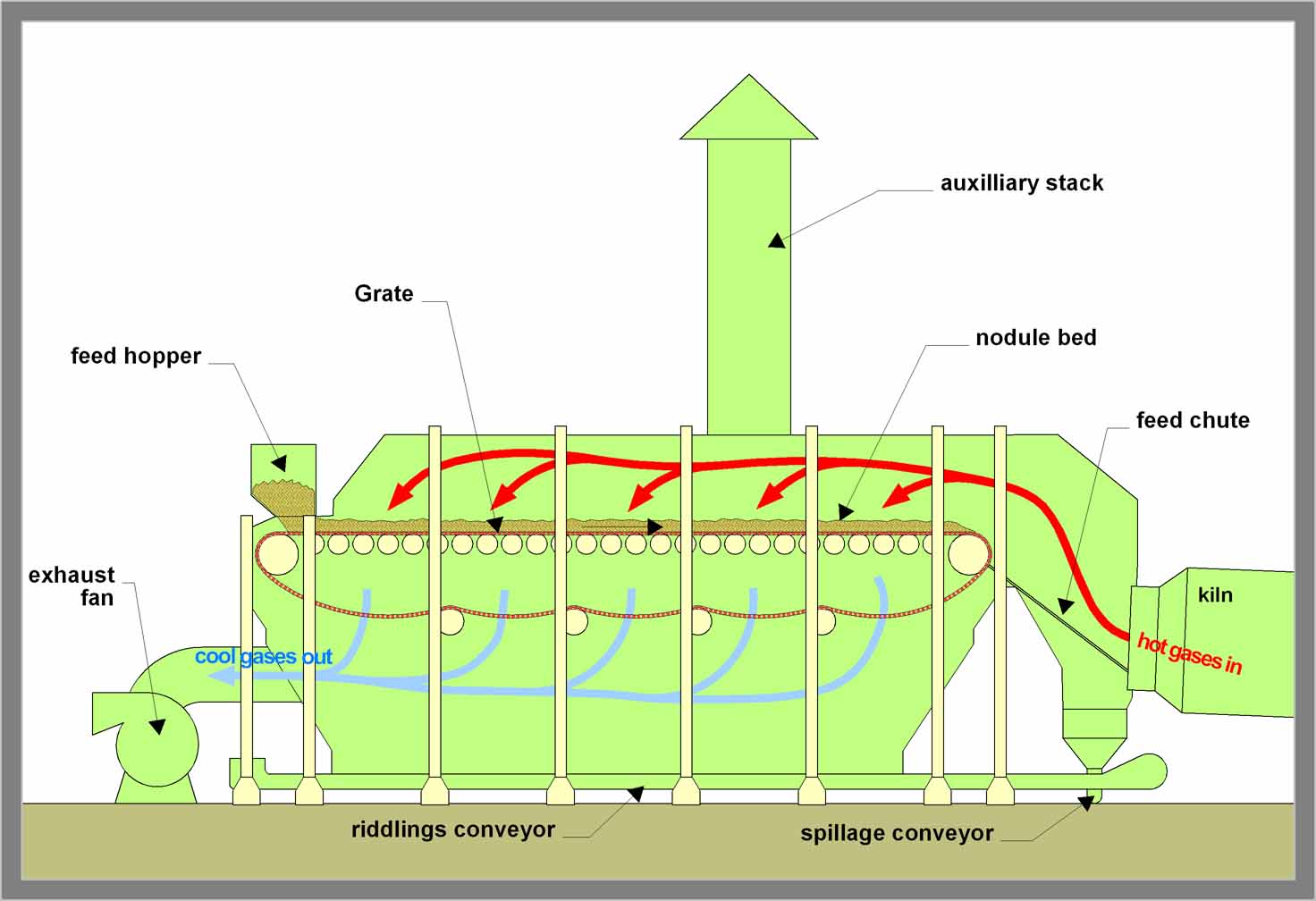
"Vickers Moving Grate"
This is essentially the Lepol single-pass grate. The grate is contained inside a steel-plate enclosure. The part above the grate is arched so that it can be insulated with arched brickwork. The 0.15-0.30 m layer of feed protects the grate from the hot kiln gas, which is at 1000°C or more. If the movement of the grate stalls, this cooling action ceases, and the steel of the grate can burn. An auxiliary stack is provided to vent the hot gas if this happens, but in normal operation, the kiln exhaust is pulled from below the grate by the main kiln ID fan. The feed bed acts as a relatively efficient filter for the dusty kiln gas, and in the days before kilns were fitted with proper dust filters, grate kilns emitted less dust (1-2% on clinker) than other kiln types. In the feed bed, a certain amount of fine material is produced as a result of abrasion and breakage of the nodules. The fines tend to be pulled through the grate by the draught, and settle out as "riddlings" in the base of the grate compartment. These, and material that spills over the back of the kiln, were gathered by screw or drag conveyors, and were usually lifted by an elevator and dropped back into the kiln.
Vickers sold none of these grates in the UK, nor anywhere else to my knowledge. By the time of the first British Lepol installation in 1957, the "double-pass" design had become standard.
A 1953 article described the world-wide progress to date: 120 single-pass Lepol systems had been installed up to 1948, with typical output 200-300 t/day. The post-war West German Polysius company developed the double pass system and all orders on the books from 1948 onward were completed as double-pass, and six were in operation by 1953.
Large single-pass Lepol grate used for dolomite calcination at Steetley Dolomite Ltd, Thrislington: picture kindly donated by Tom Mottram.
The single-pass grate is a cross-current heat exchanger. Because the nodule bed gets hotter as it moves along, gas passing through the hot end of the grate receives comparatively little cooling effect, and so the temperature of the mixed exhaust gas is raised by this. The efficiency of heat recuperation is greatly improved by the "pseudo-counter-current" design of the double-pass arrangement. A further problem of the single pass grate is that fresh, damp nodules were subjected to drying by very hot gas, the evaporation rate often being sufficiently fast to cause the nodule to explode or "pop". In single pass grates, this was ameliorated by bleeding in ambient air over the feed end of the grate, to the detriment of efficiency and fan capacity. The double-pass system allowed a more controlled application of heat.
Double pass grates
Here the grate enclosure is divided into two chambers, conventionally called the drying and calcining chambers. Hot gas that has passed through the feed bed into the bottom of the calcining chamber is pulled through cyclones by intermediate fans and is ducted into the top of the drying chamber. The final fan then pulls it through the feed bed again. At the expense of increased fan power, the cyclones protect the intermediate fans from dust, and prevent the dust from blinding the drying chamber bed. There were six cyclones on the 20.9 m grates, eight on the 27.7 m grates, and eight each side of the 44 m grate at Rochester.
Diagram of double-pass arrangement
Because the grate passes through the chamber dividing wall, gases can leak between the chambers. This leakage is minimised by controlling the intermediate fan power to keep the two chambers at the same pressure, so that only a small amount of gas diffuses through the gaps. The conventional design once again gathered the riddlings and back-end spillage, along with the cyclone dust, and returned them to the kiln hearth. All the UK Lepol systems were of this design.
Behaviour of the feed bed
Aside from the improvement in theoretical heat exchange efficiency, this system has the distinct advantage that the nodules undergo a gentler heating-up regime. In the single-pass arrangement, fresh, damp nodules are potentially subject to heating with gases at 1000°C or more, straight from the kiln. This results in thermal shock which can cause the nodule to explode, producing dust and fine fragments that can block the gas flow through the bed. In the double-pass arrangement, the gases in the drying chamber are much cooler (about 350°C), and the problem is reduced. In some instances, the temperature is further reduced by re-circulating some of the cool exhaust gas to a point in the roof near the inlet.
Nevertheless, the issue of nodule strength remains decisive in the success of a Lepol system. Nodules have to have a number of often incompatible properties. They must be porous, to allow steam and CO2 to escape, but must also be strong, to resist crushing during handling and to survive thermal shock. Small nodules are less prone to "popping" during out-gassing, but are mechanically weaker. In general, a compromise nodule size is 10-15 mm in diameter, and water content is 11-15% by mass. In comparing different Lepol systems, the strength and abrasion resistance of the nodules correlates remarkably well with kiln output. In addition to the blinding of the bed due to nodule "popping", the fines produced increase the amount of cyclone dust and riddlings which, when returned to the kiln, tend to be carried back into the calcining chamber, and blind the bed there again. The amount of cyclone dust (as a percentage of clinker production) varies from 0.5% to 3% depending on abrasion resistance, while the amount of riddlings (due to breakage) varies from 1% to 20%. The most productive kiln produces so little of either that they can be economically dumped, thus avoiding the dust re-circulation problem altogether.
Another set of problems arise from the peculiar properties of the well-made Lepol nodule: the nodules maintain their original shape and size right through the kiln. The resulting porous clinker nodule gains and loses alkali salts in liquid and vapour form more easily than do other clinkers. This results in thick coating on the brickwork of Lepol kilns. This has the beneficial effect that Lepol kiln brickwork is well protected from damage, so that Lepol systems usually have long refractory life and low refractory replacement costs, and heat loss through the kiln shell is low. The downside is that, if the kiln is unstable or erratically run, the coating can take the form of rings that choke the kiln. Fairly frequent stops to remove rings are rather characteristic of most Lepols. Historically, rings were removed by shooting out with an industrial cannon: in more recent times, high pressure water jets have been used. The other problem that arises is the large amount of alkali salt fume that can be driven out of the feed and coating if the kiln burning zone heats up for any reason. This fume, on entering the preheater, condenses as liquid droplets on the feed bed, which then cause dust to adhere to the surface, causing "hot blinding". This causes a very rapid rise in the pressure drop across the bed, and if the intermediate fan runs out of capacity to overcome this, the kiln draught drops and the burning zone heats up even more. Dealing with this requires severe adjustments which exacerbate the instability and cyclic behaviour of the system. In one instance at least (Rochester A6), an alkali bleed has been provided on the calcining chamber in order to intercept alkali surges before they cause a cycle.
Typical operation
Lepol grates in normal operation have the following parameters:
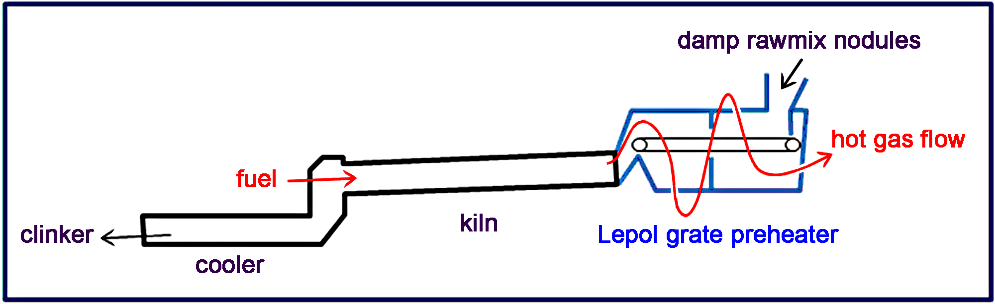 Lepol kiln layout
 "Vickers Moving Grate"
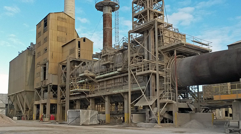
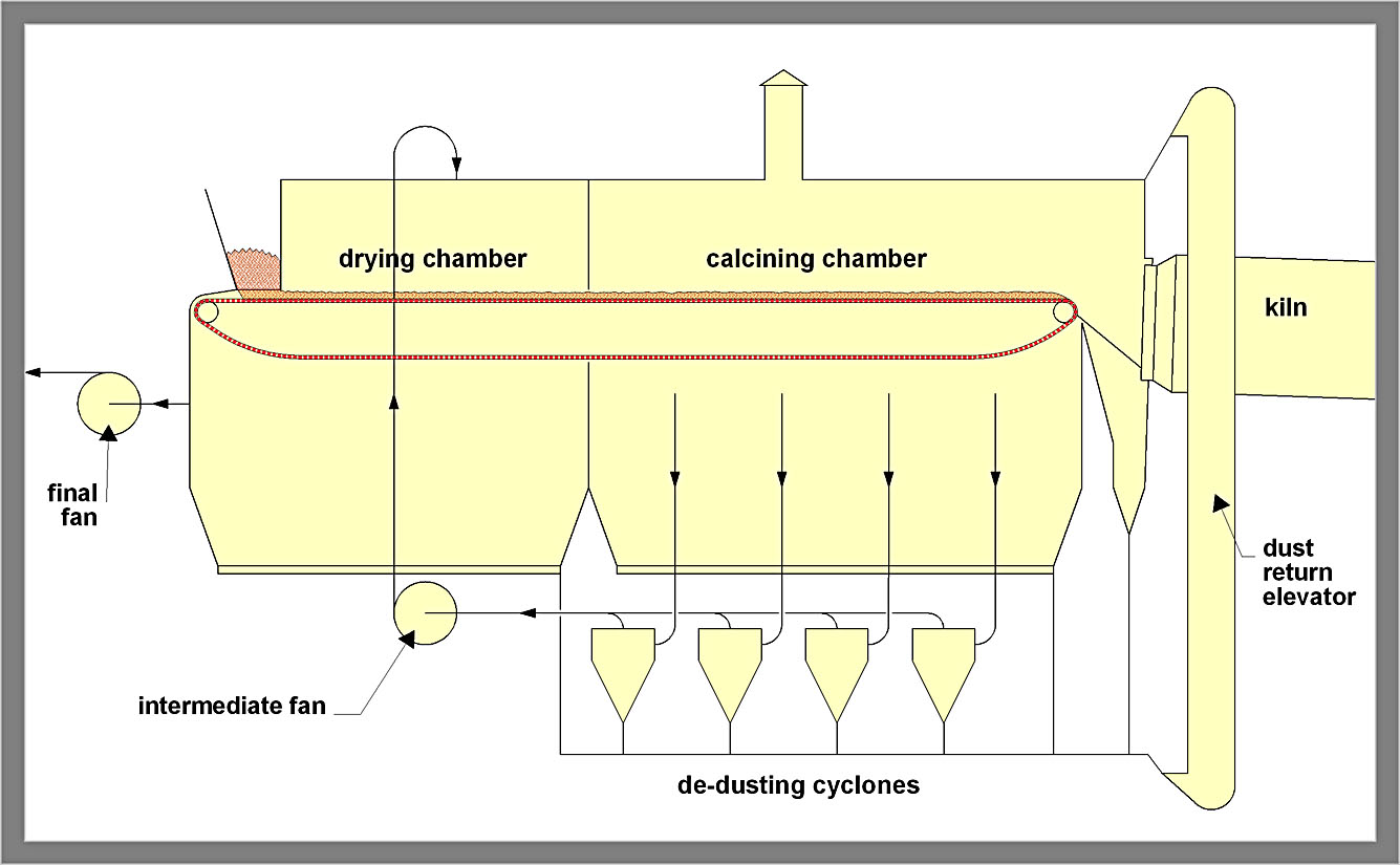 Diagram of double-pass arrangement