The following is a transcript of an anonymous article that appeared in The Engineer, 140, 1925, p 124. It is believed to be out of copyright. It describes the third rotary kiln installed at West Thurrock plant, which was the first kiln to be provided with a Unax cooler.
A Combined Rotary Cement kiln and Clinker Cooler
In cement works employing rotary kilns, it is the custom to cool the clinker as it comes from the kiln in a separate inclined rotating cylinder, arranged either in line with the kiln or vertically below it. In the first case the clinker proceeds in one straight line from the point where the raw materials are fed into the kiln till the burnt material issues from the cooler. while in the other case the direction of progress of the clinker is reversed when it is delivered from the kiln.
Various attempts have been made to combine the kiln and the cooler in one unit, but, so far as we are aware, they have hitherto none of them been entirely successful (Note 1). There has, however, just been brought to our notice a combined kiln and cooler which has recently been patented and put upon the market by F. L. Smidth and Co., Ltd., of Copenhagen and Victoria Station House, Victoria-street, London, S.W.1, and which is claimed not only to perform its work satisfactorily, but to effect a saving of coal as compared with the consumption when using separate kilns and coolers. The name "Unax" has been applied to the combined apparatus, and an example of it has recently been put into operation at the works of the Tunnel Portland Cement Company, Ltd., at West Thurrock.
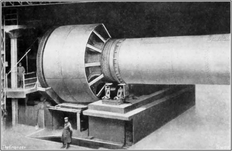
The kiln proper is of the ordinary type, but as will be observed from the accompanying illustration, there is, at the firing end a portion which is of considerably larger diameter than the kiln tube, and it is in it that the cooling of the clinker is effected. We are, unfortunately, not permitted to reproduce a sectional drawing of the apparatus (Note 2), but the following description will serve to give an idea of its general construction :— The cooler comprises a series of tubes arranged around a central cylinder, which is of about the same diameter as the kiln, and the axis of which is in line with the axis of the kiln. It is provided with a thin lining of refractory heat insulating material, and is closed at the end remote from the kiln with a cap or hood of similar design to the firing hoods of ordinary rotary kilns. Kiln and cooler being rigidly connected together revolve, of course, as a single unit. The refractory lining of the kiln is prolonged into the cooler—the discharge orifice being constricted by an extra thick layer of it—and is taken up to the entrances to the tubes, which are themselves lined for a short distance with refractory material. The rotation of the kiln discharges the burnt clinker into the cooler along the tubes in which it passes, meeting on its way air from the outside as it rushes in to support the combustion of the fuel in the kiln. The results are that the clinker, as it makes its way to the open ends of the tubes, is cooled and the combustion air is heated. The coal dust fuel pipe is taken through the hood in the usual way, and is led through the central cylinder of the cooler—on the centre line horizontally and rather above the centre line vertically—the discharge end pointing downwards at a slight angle, and terminating just before reaching the end of the kiln. There is, therefore, no great length of pipe to support—no more indeed than in an ordinary rotary kiln equipment—and it is shielded from the heat radiated by the clinker.
The makers claim the following advantages for this kiln:—(a) Separate coolers are eliminated; (b) the cooling of the clinker is efficiently performed; (c) there is no loss of heat between the clinker and the cooler, which results in a less consumption of fuel; (d) the foundations required are of less length than with separate kilns and coolers; and (e) the building accommodating the kiln can be made lower. As substantiating the claim that the consumption of fuel is less with the "Unax" than with other kilns for a given output, the makers inform us that careful tests with the former have shown a saving of about 5 per cent.