The following is a transcript of an anonymous article that appeared in The Engineer, 106, 10/7/1908, pp 30-32, which is believed to be out of copyright.
The Irthlingborough plant began in a small way in 1898, but was reconstituted as the Premier Portland Cement Company in 1907 and re-built as a dry process rotary kiln plant. The renewal of the plant was already underway, since the kiln was ordered in 1906, and it may be that the new company was formed in order to raise extra capital mid-project.
The Irthlingborough area had been exploited (and geologically surveyed) for iron ore extraction since 1890, and iron works were operating in Wellingborough nearby. The cement plant and the several brickworks in the area were probably set up in order to exploit the limestone and clay overburden of the iron workings. This secondary role, combined with competition from other larger Midland cement firms, caused the plant to fall behind in technology and close in the late 1920s. But the plant discussed here, only a short time after start-up, was fairly well-conceived, and represented on a small scale what was on offer for dry process plants at the time.
Values of imperial units (as of 1929) used in the text (alphabetical order): 1 acre = 0.40468424 Ha: 1 ft = 0.30479947 m: 1 gallon = 4.5460756 dm3: 1 HP (horse-power) = 0.7456998 kW: 1 inch = 25.399956 mm: 1 psi (pound-force per square inch) = 6.89478 kPa: 1 ton = 1.01604684 tonne: 1 yard = 0.91439841 m.
CEMENT WORKS AT IRTHLINGBOROUGH.
At Irthlingborough, which is situated some four miles from Wellingborough, on the Midland Railway, and joined by a siding to Higham Ferrers Station, on the London and North-Western Railway Company's line between Northampton and Peterborough, are the cement works of the Premier Portland Cement Company, Limited. This company is fortunate in possessing on its site, besides other things, deposits of Oolitic limestone and Upper Lias clay. These two substances, when mixed together in the proper proportions, form a compound which, on being burnt, becomes Portland cement of excellent quality.
We were recently invited to visit these works, and were shown over them by Mr. W. A. T. Flitton, the company's manager, and we propose to describe them in the following article:—
The "dry" process is practised at these works. The limestone exists in layers not far from the surface, and is easily quarried, but little blasting being required. The overlying matter possesses all the qualifications of the flux required for the production of pig iron (Note 1), and as there are blast furnaces in the neighbourhood, a ready outlet is found for this material. The depth of the limestone deposit (Note 2) varies, but it may be taken as averaging about 10ft. to 12ft. The stone itself is much broken up into layers and by vertical cracks, the spaces between layers and between adjacent blocks of stone being filled up by a soft material of a more or less clayey nature. The whole formation rests on a deep bed of bluish clay (Note 3). This latter is not of the requisite composition for the manufacture of cement, and is, therefore, not quarried. The method of quarrying carried out by the company is first of all to remove the top soil and lay it aside; then to transfer the flux material to trucks for conveyance to the blast furnace works, and finally to take out the best portions of the limestone down to the level of the blue clay above mentioned. In the quarries — of which there are at present two — the stone is roughly broken up by hammers into blocks of sizes suitable for packing into narrow-gauge railway trucks. The material is soft, so that this process is easy to perform. When the whole is removed, the top soil taken away in the first instance is replaced on the clay, and we understand that the land is then again employed for agricultural purposes, as the original ground surface is at the present time.
Lines of narrow-gauge railway are employed for the purpose of transporting the limestone to a position near the works, which are some 500 to 600 yards away, and the trains of trucks are hauled by what is an almost perfect copy of a main line locomotive engine in miniature. Rope haulage used to be employed. but recently resort has been had to this locomotive, with, we gather, satisfactory results. The stone is not at once taken into the works, but is allowed some time to " weather," this process removing the soft material which forms the natural setting of the stone in the quarry (Note 4).
The necessary clay is obtained from another part of the company's lands, and it occurs in a deep deposit with a layer of considerable thickness of ironstone overlying it (Note 5). Curiously enough a fault runs right through the company's property, and on that side of it on which the limestone is quarried the ironstone is at a depth of some 90ft. (Note 6), while on the other side of the fault it is nearly on the surface. As in the case of the flux material, the ironstone, which contains some 35 per cent. of iron, is disposed of to the blast furnaces in the neighbourhood. The clay is brought up from the pit by means of rope haulage, this method being here still employed satisfactorily, as the pit is much nearer the works than are the limestone quarries (Note 7).
The company has therefore to its hand the two ingredients necessary for the manufacture of cement. All that is requisite is that they should be properly mixed and in the proper proportions. We may mention that though a certain number of fossils is found, flint is practically absent. It will be interesting perhaps if we give the analysis of the limestone and the clay. That of the former is as follows:—
| Analysis of Oolitic Limestone | |
| Water and organic matter | 1.10 |
| Silica | 6.47 |
| Alumina | 2.37 |
| Ferric Oxide | 1.24 |
| Calcium Carbonate | 87.42 |
| Magnesium Carbonate | 1.26 |
| Sulphur (in any form) | Nil |
| Alkalis and loss | 0.14 |
| Total | 100.00 |
It will be seen that the limestone is rich in calcium carbonate. The composition of the clay used is shown in the following analysis:—
| Analysis of Upper Lias Clay | |
| Water and carbonic acid | 10.87 |
| Silica | 54.12 |
| Alumina | 22.80 |
| Ferric Oxide | 6.33 |
| Lime | 2.14 |
| Magnesia | 2.45 |
| Sulphur | 1.69 |
| Alkalis and loss | 0.44 |
| Total | 100.84 |
| less Oxygen equivalent to sulphur | 0.84 |
| 100.00 | |
A point to notice in connection with this clay is the high proportion of iron. As a matter of fact, the proportion of iron in the finished cement is also high, as will be seen (Note 8). This, however, has no deleterious effect, and only makes the cement a little dark in colour, though the difference in this respect between it and other cements is barely noticeable. The finished cement has the following average composition:—
| Analysis of Premier Portland Cement | |
| Water and carbonic acid | 0.70 |
| Insoluble residue | 0.35 |
| Silica | 21.73 |
| Alumina | 7.76 |
| Ferric Oxide | 4.84 |
| Lime | 61.60 |
| Magnesia | 1.22 |
| Sulphuric anhydride | 1.78 |
| Alkalis and loss | 0.02 |
| Total | 100.00 |
The weathered limestone and the clay are brought in trucks up an inclined way to a platform situated over the driers. Both materials are then in large pieces, and it is necessary to break these up before they undergo any further process. The stone is broken in a reciprocating jaw crusher, the blocks of material being thrown down a shoot and being broken up into quite small pieces before they reach the charging level of the driers. The clay is also thrown down a shoot and passes through a pair of toothed rollers which completely disintegrate the lumps. The discharge from both machines is respectively into one or other of the two driers which are marked A on the plan—Fig. 1. It should be mentioned that this plan is taken at a level below that of the crushers, and hence does not show them. The driers are tubular in shape and some 36ft. 6in. long by 4ft. 6in. in diameter. They are traversed by the heated gases coming from the rotary kiln. When the driers are not at work, which happens on Sundays, and at other times when the stock of dried raw materials is in excess of requirements, the kiln gases are discharged through the chimney at B; but when they are in operation the gases, after traversing the driers, escape through the chimney at C. It may be noted in passing that, whereas the chimney at B is lined with firebrick, this precaution has not been found necessary in the case of the chimney at C. It will be noticed that the usual arrangements for arresting and removing the dust from the flues have been made.
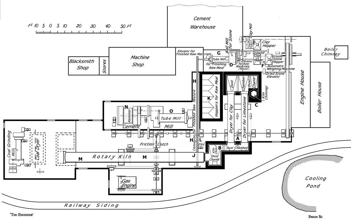 Figure 1: Schematic Plan
The Swain original has been augmented for clarity.
The dried stone and clay are taken to their respective elevators, where they are shot into hoppers. The stone is elevated to a conveyor which takes it to a ball mill marked D on the plan. Here it is reduced to a fine powder, and is then returned by a conveyor to an automatic weighing machine marked F. Meanwhile the clay has been elevated to the mill E, and, after being ground to powder, is itself returned to the weighing machine, the function of which is automatically to arrange that the correct proportion of each material shall pass forward for further operations. This ingenious contrivance works as follows:—
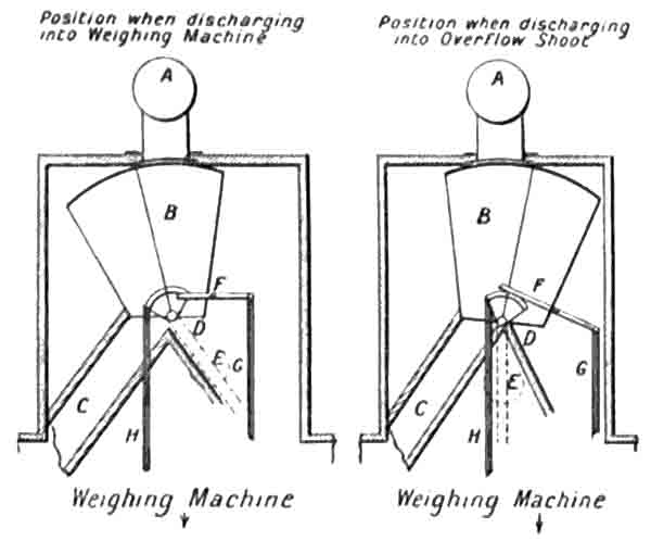 Figure 6: Drawing of Raw Material Batching System.
There are two weighing machines arranged side by side close together, the stone machine being capable of weighing 200 kilos. and the clay machine 40 kilos. Each is fed by a worm, and the speed of these worms is arranged so that the machine weighing clay is always filled first. As soon as the clay weigher has received its charge, the pan containing the weights moves upwards, and, in doing so, strikes a small lever, which releases a counterweight attached to the two-way shoot which feeds the machine. This two-way shoot works thus (see Fig. 6 which is diagrammatic only and not in any way drawn to scale):— In this drawing A is the feeding worm; B the two-way shoot; C the overflow shoot to the elevator; D the shoot to the weighing machines; and E the counterweight. F is a stop lever for keeping the shoot in position while the machine is filling. This lever is raised, and allows the counterweight to fall into a vertical position by the belt G, the latter being attached to a lever that is actuated by the weighing machine when making the preliminary tip. H is a belt for pulling the shoot back into the position for filling the machines.
When the machine has filled, the ground clay runs back to the foot of an elevator, which raises it again into the hopper over the machines. As soon as the stone weighing machine has received its charge, it commences to tip, and, in doing so, releases an automatic coupling arrangement, which is one of the chief features of these machines, and allows the clay machine to tip at the same time. Both machines after tipping come back to their original positions, and in doing so, they pull over, by means of a smaller leather belt, the counterweight attached to the two-way shoot before mentioned, which brings this shoot into position for filling the weighing machine again (Note 9). There are two-way shoots and counterweights attached to each machine, so that, should the stone weigher weigh first at any time, through the material running through the feeding worms, no error in weighing occurs. These machines work very accurately (Note 10), and the raw mixture never varies more than 0.5 per cent. Attached to the apparatus is an automatic recorder which shows how many times the hoppers have tipped, and consequently how much weight of material has passed through. The men are paid according to the record made by this counter.
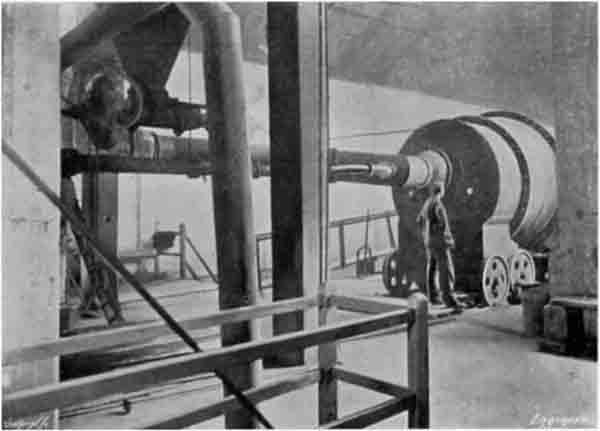 Figure 2: Kiln Firing Floor. FLS kilns at this time diverted all the cooler air through the coal drying/grinding plant, then re-introduced it at the hood. So the over-large duct is effectively the secondary air duct, and the higher-pressure firing pipe - only 4" ID - runs concentrically inside it. At the top left is the bottom cone of the fine coal hopper, with the twin barrel screws that dose the coal into the firing pipe. The structure to the right may be the casing of the raw coal elevator, while that on the left is the dry coal elevator between the dryer and the coal mill.
The ground stone and clay having been mixed in the right proportions in this apparatus, the resulting "raw meal" is taken by a conveyor to an elevator, which lifts it to the level of the feeding shoot to the tube mill G. In this the compound is still more intimately mixed, and is also ground to such an extent that there is only a residue of 15 per cent. on a sieve with 32,400 openings to the square inch. The delivery from this mill is into the hopper of an elevator, which lifts the mixed and ground raw meal into the long conveyor marked H. There are, though they are not shown on the plan, several extracting worms working in the hoppers K, which deliver when required into the conveyor H. The duty of these hoppers is to be explained immediately. The conveyor H takes the raw meal to the elevator L, which raises it to above a hopper—not shown on the engraving—which supplies a worm feed to the kiln M. The delivery from this hopper is considerably less than the amount which the elevator can raise, and consequently an arrangement has been made by which the surplus amount lifted is diverted into the hopper K already mentioned. This therefore acts as a store of raw meal, and the arrangement also serves to keep the whole body of the material in constant circulation, since, as we have already mentioned, there are conveyors from it delivering into the conveyor H (Note 11). Moreover, by the addition of this storage hopper it is possible to work the drying and grinding plant without the kiln, and to feed the kiln when the drying and grinding plant is not working. We would also call attention to the conveyor J, which delivers into the elevator L the raw meal dust which collects in the dust chamber in the base of the chimney, being carried there by the draught through the kiln during the process of feeding.
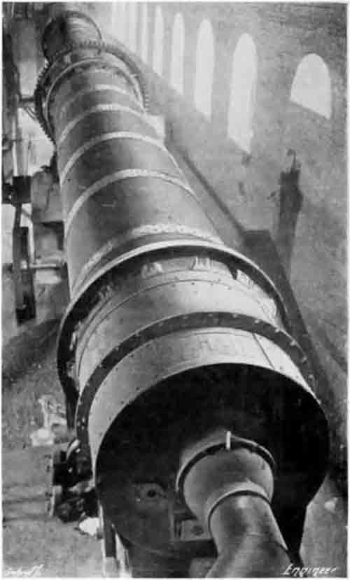 Figure 4: The Kiln. Viewed from the top of the fine coal hopper. On the left, the cooler drive can be seen, and the huge pile of clinker spillage banked against the second pier (see Figure 3).
The rotary kiln itself is of a type similar to that at the works of I. C. Johnson and Co., Ltd., at Greenhithe, which was described in our issue of the 28th February last. It is, however, considerably longer, being about 100ft. in length, and its diameter is 7ft (Note 12). It, as well as the remainder of the equipment of these works, was supplied by the same firm, namely, Messrs. F. L. Smidth and Co., of Copenhagen. It is geared and driven in almost exactly the same manner as the other kilns just referred to, and has two speeds, 1 and ½ revolution per minute respectively (Note 13). The similarity between the two plants extends also to the coal drying, grinding, and feeding arrangements, as well as to the method of cooling the clinker. We need not, therefore, go into these questions in any great detail, but we may just outline the method of working. The burnt clinker, as it descends from the lower end of the kiln, is led into a cooler, which is situated directly under the kiln, and is therefore not visible in the plan—Fig. 1— though it may be seen in the engraving—Fig. 3. This cooler consists of two tubes, one inside the other; the inner tube does not quite go to the end of the other tube, so that the clinker is deposited from the inner tube into the outer, the end of which near the delivery of the smaller tube is closed. Both the tubes revolve, and the result is that the clinker, having passed along the inner tube and into the outer tube, has to make its way back again to the open end of the latter (Note 14). Meanwhile a large volume of cold air is being drawn in through the cooler over the clinker, which has the effect of considerably cooling it, so much so that, whereas on coming out of the kiln at a white heat, the clinker, on its exit from the cooler, is at such a temperature that it can nearly be held in the hand. The heated air is used to dry the coal (Note 15), which is then ground in a tube mill, and elevated to a hopper above the firing end of the kiln. The feeding arrangement is a worm conveyor, the speed of which may be regulated by means of a friction wheel and revolving disc, so that by placing the wheel at varying distances from the centre of the disc, any required speed may be obtained. The coal is then blown into the kiln through a nozzle by means of the hot air.
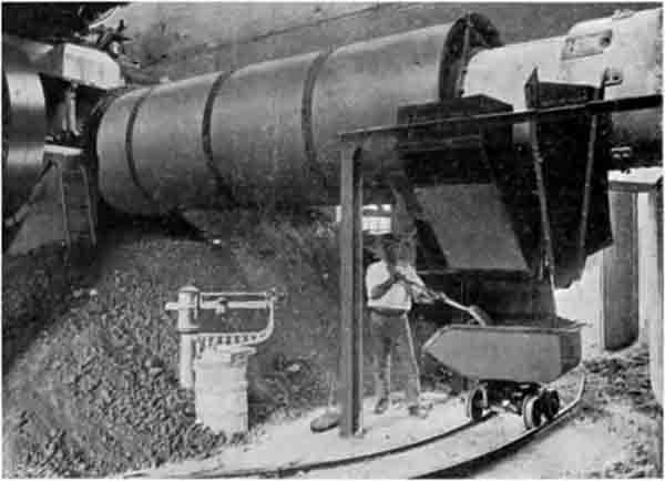 Figure 3: The Cooler. This is a concentric rotary cooler such as was supplied by FLS and others before 1920. The design allows the cooler to be shortened so that it need not pass through the second kiln pier. The clinker should fall directly into the skip. The huge pile of spillage, burying the weigher, should not of course be there. To the left, the crown wheel on the end wall of the cooler is visible, as is the drive pulley. This is clearly stationary. A common problem with belt drives is that, if overloaded, they stall. If a stalled cooler is not noticed immediately, it will rapidly fill up with clinker and become immovable. The only recourse is then to open a door on the cooler (presumably on the other side) and let it all run out on the floor.
The cooled clinker, which, we may say, is of good quality and thoroughly well burnt, is received into narrow-gauge railway trucks, and is then wheeled outside into the open, where it is allowed to weather. The Premier Company has found that by doing this the work of grinding is rendered much less arduous, since a considerable amount of disintegration of the lumps of clinker takes place when these have been exposed to the air and weather for some time.
There yet remains to be described the process of grinding. This is carried out in two stages, the first taking place in a Kominor mill and the second in an ordinary tube mill. The weathered clinker is brought in barrows by hand from the weathering heaps, and is shot into the hoppers of an elevator. This delivers it on to a revolving feed-table, the shoot from the elevator descending to a point close to the revolving table, so that not more than a certain amount can be delivered to the table at one time. A hinged arm, which is pivoted at the side of the table, can have its angle altered so as to divert more or less material from the table into the shoot leading to the Kominor grinder as the table revolves. The power to drive the mechanism working the table is transmitted through a thin wooden peg, so that if anything sticks the peg shears, and no harm is done. The discharge from the Kominor grinder is taken to the tube mill marked O on the plan, where the grinding process is completed, and the cement reduced to such a fineness that there is only a residue of 15 per cent. on a sieve with 32,400 openings per square inch (Note 16).
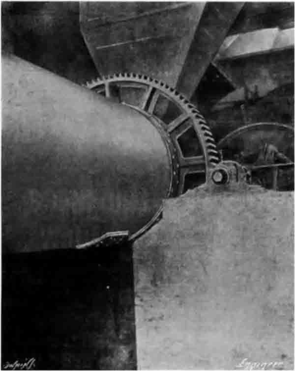 Figure 5: Finish Mills. This is the inlet end of the tube mill, with the drive via a spur ring. The drive pulley is behind the bearing pier, and is connected by a belt to the main lay-shaft off to the left. The first-stage grinder - the Kominor ball-mill - was also at ground level, beyond this view. It discharged into an elevator, which delivered into the feed-chute shown. Scaling from the plan, the tube mill was probably 5.75 × 1.70 m, and if charged with flint would be rated at about 50 kW and make 3-4 t/h.
The finished material is then elevated on to a rubber band conveyor, by which it is taken into the cement warehouse. Here, by an arrangement of conveyors and shoots, it can be delivered into any required bin. A siding from the railway runs close beside this warehouse, so that it is easy to load bags of cement into wagons.
The motive power for driving these works has been arranged in duplicate. In the first place, there is a Pollitt and Wigzell tandem compound horizontal jet condensing steam engine capable of indicating 500 horse-power. This is supplied with steam from a Lancashire boiler 8ft. in diameter and 30ft. long. The condensing water is cooled in a pond near by, the cooling being further effected by pumping the condensed water to the top of an exposed screen, and letting it flow down into the pond over a series of baffles. From the main engine pulley the main drive is brought about by a 30in. belt, running at about 56ft. centres, which works into a main shaft, as will be seen in the plan. From this shaft the driers, kiln, cement grinders, conveyors, &c., are driven, and the coal preparing machinery by means of a rope transmission, this being the only rope running in the works. Off another pulley on the engine another belt drives on to a shaft which works the raw meal grinding, elevating, and conveying machinery, as well as a small dynamo which is used for lighting purposes.
As a stand-by a 75 brake horse-power Campbell gas engine has been laid down. This drives on to a cross shaft which is geared by bevel wheels to the main driving shaft already mentioned. This engine is used when it is necessary to clean the boiler or to effect any necessary repairs to the engine. It is also used when it is required to run one or more portions of the plant without the others, and is coupled up by means of a clutch. The equipment of the works is completed by machine and blacksmith's shops, and by two laboratories, one for chemical and one for physical tests. Both these are carried out with care and regularity, and complete records are kept in both cases. Both laboratories are presided over by Mr. P. S. Barber, chemist to the company. We had the opportunity of seeing two briquettes, seven days old, broken in the machine. One of these, which was made of neat cement seven days old, broke at 660 lb., and the other, 1 to 3 standard sand, broke at 350 lb. (Note 17). Unless requested to do otherwise, the company always works to the British standard specification. The output of the works is stated to be about 450 tons per week.
We are enabled to reproduce a number of views of the works in the accompanying engravings. Fig. 2 shows the firing platform of the kiln. In it may be seen the coal feed and the air supply pipe. Fig. 3 shows the clinker being delivered into a truck from the cooler. Fig. 4 is a view looking down from up above along the kiln from the firing end. Fig. 5 represents the driving end of the tube mill for grinding the cement. Fig. 8 shows the raw material platform, and the house containing the crushers and driers. The end of the engine and boiler-house may also be seen, and the two kiln chimneys, as well as the cooling pond. Fig. 7 is a view in the chemical laboratory.
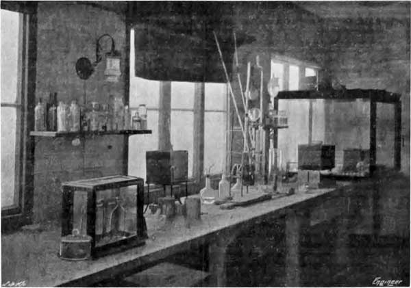 Figure 7: Chemical laboratory.
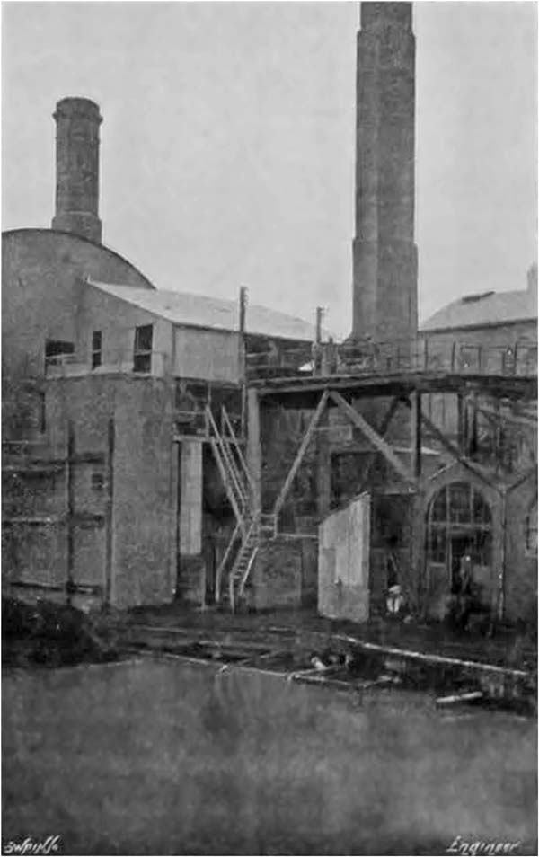 Figure 8: Raw Material Gantry. The kiln stack is to the left, and the dryer exhaust stack to the right. The cooling pond is in the foreground. The gantry is used to raise raw material to the crusher inlet.