Coltness

Coltness Newmains Caledonian Brand cement logo
Caledonian Brand. The Caledonian Portland Cement Co. Ltd. distributed the product of Coltness, Gartsherrie and Wishaw from 1929.

Location:

Clinker manufacture operational: 8/1914 to ?1959

Approximate total clinker production: 1.15 million tonnes

Raw materials:

Ownership: Coltness Iron Co. Ltd

Also known as Newmains Works. The iron works had experimented with slag/lime cement from the late 19th century, and from 1907 constructed substantial plant to make activated slag by the Colloseus Process. In an article in The Engineer, CIX, January 21, 1910, pp 60-61, they were described making activated slag under licence of the patentee: the treated slag is referred to as “clinker”, and the ground product is referred to as “Portland cement”. Evidently, the news that a British Standard for Portland cement had been published, had not yet reached Scotland.

Following the failure of this, they set up to make Portland clinker in 1914 using air-cooled slag as a mix component. This involved adding a rawmill and kiln system to the already substantial grinding plant. The clinker was then inter-ground with granulated slag (up to 70%). A separately-heated rotary drier was used to dry the granulated slag, but the kiln raw materials were ground by ball mill without drying: the slag was probably usually sufficiently hot to supply enough heat for this. The plant was substantially renovated in the mid-1930s. The Coltness company operated the plant, and brick, concrete and general engineering businesses as a sideline to their main interests of steel and coal mining, and after nationalisation, a rump company continued to run these peripheral concerns. The economics of the plant depended on the ability to offer pbfc at a lower price than Portland cement from England, and this became progressively less viable through the post-WWII period. The plant shut down with the purchase by Blue Circle of the limestone mine for Dunbar, and the prospect of an efficient cement plant in Scotland. The plant had excellent rail communications and used these for raw materials and product. The buildings remained in place into the 1980s, with the concrete products plant, taken over by Costain, remaining in operation, but the whole steelworks site was cleared in 2004.

The later history of this and the other Scottish slag-based plant (Wishaw) is hard to obtain. Coltness made its last cement in October 1963, but it may be that clinker production ceased much earlier. I am keen to get hold of information on their post-war activities. Please contact me with any relevant information or corrections. I am particularly interested in firmer dates and statistics, pictures and plans.

Power Supply

The plant was electrically powered from the outset, using power produced by the iron works using generators driven by gas engines running on blast-furnace exhaust gas. With the shut-down of the blast furnaces in 1927, purchased power from Motherwell was used.

Rawmills

Two rotary kilns were installed:

Kiln A1

Supplier: Pfeiffer
Operated: 08/1914-?1926
Process: "Long" dry
Location: hot end 282444,655341: cold end 282447,655307: enclosed.
Dimensions: 35.00 × 2.450B / 1.800CD
Rotation (viewed from firing end): anticlockwise
Slope: ?°
Speed: ?
Drive: ?
Kiln profile: 0×2100: 250×2450: 10500×2450: 13500×1800: 35000×1800: tyres at 1400, 14600, 28100: turning gear at 17000.
Cooler: concentric rotary metric 9.00 × 1.425 / 1.700 beneath kiln
Cooler profile: 0×1425: 5000×1425: 5000×1700: 9000×1700: tyre at 2700 + tail end bearing
Fuel: Coal
Coal Mill: originally indirect fired using ?Pfeiffer tube mill: from around 1924, direct fired, 37 kW No.12 Atritor
Exhaust: direct to stack via drop-out box.
Typical Output: 51 t/d
Typical Heat Consumption: 10.7 MJ/kg


Kiln A2

Supplier: Pfeiffer
Operated: ?1920-?1959
Process: "Long" dry
Location: hot end (cooler ports) 282452,655345: cold end 282457,655307: entirely enclosed.
Dimensions (from cooler ports):

Rotation (viewed from firing end): anticlockwise
Slope: 1/33.3 (1.718°)
Speed: ?
Drive: 15 kW
Kiln profile (from cooler ports):

Cooler:

Fuel: Coal
Coal Mill: originally indirect fired using ?Pfeiffer tube mill: from around 1924, direct fired, 37 kW No.12 Atritor
Exhaust: direct to stack via drop-out box.
Typical Output: ?1920-1934 95 t/d: 1934-?1959 102 t/d
Typical Heat Consumption: ?1920-1934 7.55 MJ/kg: 1934-?1959 7.25 MJ/kg


Sources::

Coltness Newmains cement plant 1 Picture 1: ©Historic England - NMR Aerofilms Collection. Britain from Above reference number SPW035860.
This was taken from the southwest. View in High Definition.

Coltness Newmains cement plant 2 Picture 2: ©Historic England - NMR Aerofilms Collection. Britain from Above reference number SPW035861.
This was taken from the northwest. View in High Definition.

Coltness Newmains cement plant 3 Picture 3: ©Historic England - NMR Aerofilms Collection. Britain from Above reference number SPW035863.
This was taken from the northeast. View in High Definition.

Britain from Above features some of the oldest and most valuable images of the Aerofilms Collection, a unique and important archive of aerial photographs. You can download images, share memories, and add information. By the end of the project in 2014, 95,000 images taken between 1919 and 1953 will be available online.

These three views were taken in 1931, at the time when the refurbishment of the plant was taking place. This involved removing some of the bottlenecks arising from the plant's hurried conversion from the Colloseus activated slag process. The original plant consisted of a slag store (the building at right angles to the others, on the left side of Picture 2) fed from the ironworks by a long ropeway. From this, slag was fed to the adjacent grinding plant. On conversion to Portland cement manufacture, this became the main clinker store, but could only be fed by trucking the clinker to the ironworks, and feeding it via the ropeway. With the refurbishment, a direct belt conveyor was installed from the kilns to the store. Also added was a conveyor from the slag drier (right of the stack in Picture 1) to the rawmill feed hoppers, ensuring a dry feed for the rawmills. A significant addition was an FK pump-based system of recirculation for the four raw meal bins (occupying the building left of the stack in Picture 1), intended to reduce the variability of the rawmix. This remained best practice for dry process raw blending until the arrival of the Airmerge process in the 1950s. Refurbishment of the kiln included replacement of the old 4-tube Pfeiffer cooler with a Vickers Armstrong Recuperator.

The following is a transcript of an anonymous article that appeared in The Engineer, 109, 21/1/1910, pp 60-61, which is believed to be out of copyright. Although the article is anonymous, it was certainly written by Bertram Blount (1867-1921). Blount was retained as a consultant by the Collos Portland Cement Company, which was set up in 1907 by Edward John Vavasour Earle (1851-1923). He used his company, Martin, Earle and Co. Ltd, as a source of working capital. The purpose of the company was to acquire the 1905 patent of Heinrich Colloseus for an activated slag cement, then to sell world-wide licences to produce the cement, and to set up demonstration manufacturing plants. The underlying philosophy was a belief that, given the relatively large production (at the time) of slag as a zero-value waste material, the slag cement, produced at much lower cost, could completely displace Portland cement as a building material. The psychology of the promoters is demonstrated by the fact that, whereas the production plant described here cost £35,000, the value placed on the patent was £1 million. In addition to the grandiosity of the promoters' expectations, the article also demonstrates a persistent tendency of promoters of such products, to re-engineer the English language to make the product sound slightly less second-rate.

THE MANUFACTURE OF PORTLAND CEMENT FROM BLAST FURNACE SLAG

The great similarity in chemical composition existing between some types of blast furnace slag and Portland cement has long been recognised (Note 1), and has given rise to several attempts to utilise this waste product of the smelting works, so as to convert it from an encumbrance into a profitable source of trade (Note 2). The advocates of research in this direction maintain that the intense heat of the blast furnace brings about a complete fusion between the component substances of the slag, whereas the lesser heat employed in the ordinary kiln producing Portland cement is insufficient to do so. They hold that this incipient fusion of the latter process is a point of weakness in the system, the incomplete chemical combination resulting therefrom being regarded as the cause of numerous defects in the cement or mortar when used under certain conditions (Note 3). Thus the disintegrating effect of some alkaline liquids, of sea water, and of great heat is attributed by them to this cause. Again, the uneven coloration seen in some cements and the consequent stains produced on certain stones, such as marble, is due, they contend, to the non-union of the metallic salts in the cement with the other constituents.

Until lately, most attempts to transform the slag from blast furnaces into a commercially useful cement have resulted in failure. The "Puzzolan" cements of America (Note 4) are derived from this source, but their use is restricted in practice to cases where the cement or concrete after setting is kept moist, as in sea-water constructions, the thoroughly dry material being, we understand, found defective in strength.

Within recent years a new treatment for blast furnace slag has been designed by Dr. Heinrich Colloseus, of Berlin (Note 5). The results obtained, both commercial and technical, have been such as to induce several iron companies to adopt this method as a further aid to the economical working of their furnaces. In addition to this, the cement produced is said to compare so favourably to that obtained from the ordinary processes of manufacture that in some cases blast furnaces of a specially designed type have been erected for the purpose of producing the cement directly instead of its being produced as a by-product of iron smelting. The composition of blast furnace slag necessarily varies with the ores used, and it is only in those cases where the chief constituents are in a certain ratio that the process is possible. Thus a slag containing above 42 per cent. of lime and not more than about 37 per cent. of silica is suitable for the Colloseus method of cement production (Note 6).

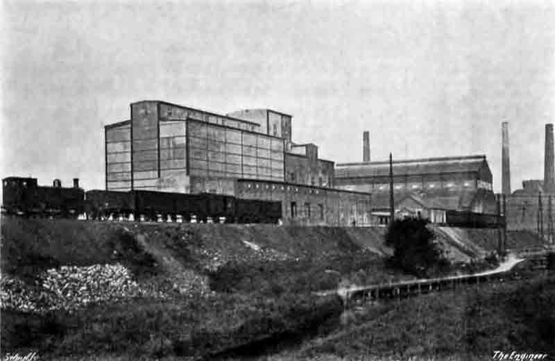
General view with the cement store and packing plant nearest, attached to the mill house behind, and the slag store beyond.

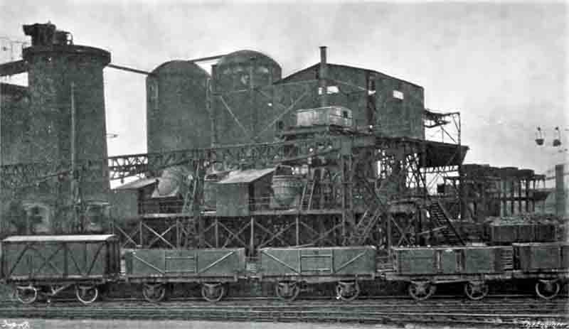
Fig. 4: Front of the granulator platform, with the end of the overhead crane gantry. Two liquid slag ladles can be seen, the one on the left in process of tipping. The end blastfurnace is to the left. The tall domed structures behind are two of the seven hot blast stoves.

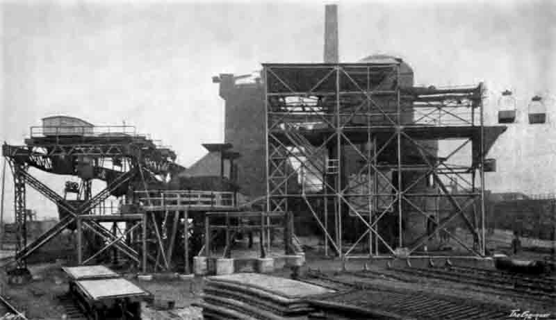
Fig. 5: Side view, showing the crane carrying ladles to the left, the two granulators centre, and the elevator raising the product buckets for transportation to the grinding plant. The row of six blastfurnaces is behind the granulators, and the solution tank is visible through the ropeway staging.

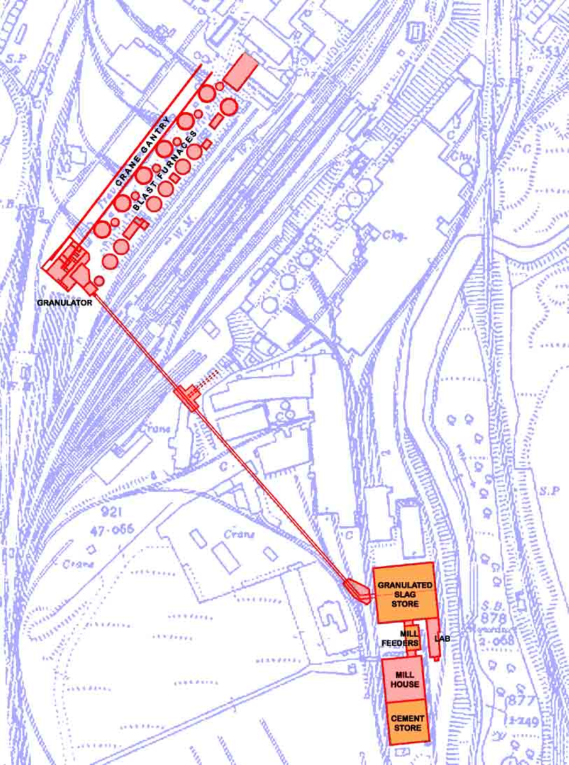
Plan based on the 1912 map showing the layout of the furnaces, granulators, ropeway and grinding plant.

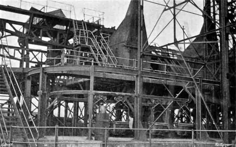
Fig. 6: Rear of the granulator platform. The ropeway buckets are queued up to receive slag from the chutes under the granulators.

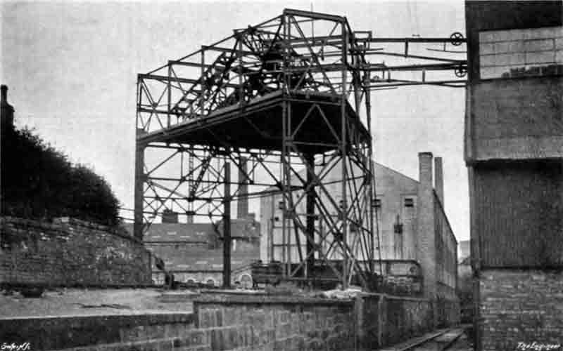
Fig. 7: The entry of the ropeway into the slag store.

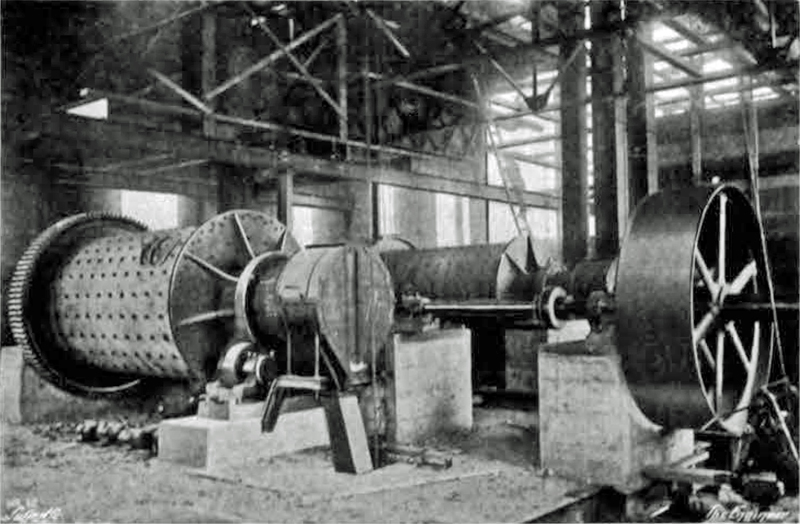
Fig. 1: Ball mills under construction.

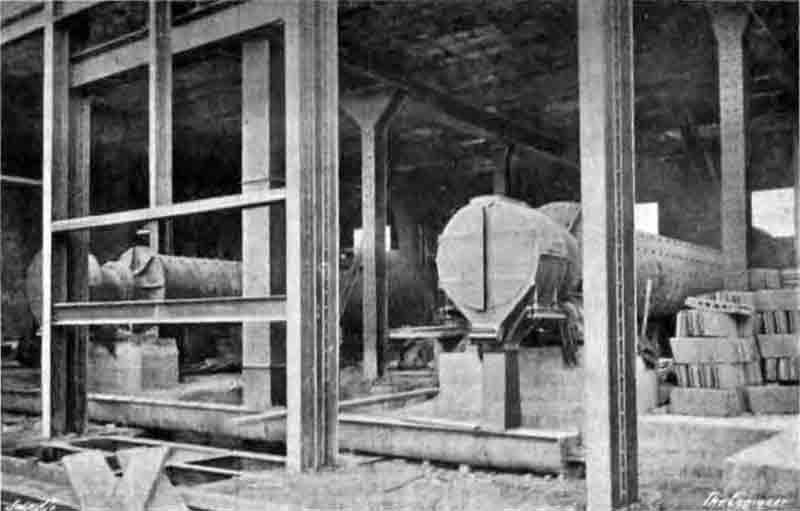
Fig. 2: Tube mills under construction.

In this country the Coltness Iron Company, Limited, Newmains, Lanarkshire, has acquired for the present the exclusive rights to work the process in Scotland (Note 7). In other countries several ironworks are employing it most successfully. At the Newmains works, which we recently visited to inspect the process as carried out there, considerable time has been given to perfecting the method and adapting its details to local necessities. The composition of the slag obtained from the hematite ores used at these works is as follows:-

per cent.
Lime50.5
Silica26.5
Alumina16.0
Magnesia2.9
Total sulfur2.6
Alkalies0.7
Manganese oxide0.5

The company has laid down an extensive plant for the economical production and handling of the slag cement. In addition to the actual producers and transporting arrangements a highly modern grinding mill has been erected and completely furnished testing houses laid down. In the accompanying engravings the extent of the plant will be seen.

The routine of the process is simple, although the chemical reactions taking place are complicated and in some cases unknown. During the smelting of iron it is customary to run off at regular intervals the slag which collects on the top of the molten iron in the furnace. At the Coltness works this slag is caught in a ladle, holding about eight tons, as it leaves the tapping hole. During the running of the iron any slag remaining in the furnace is led off from the "sow" and added to that already in the ladle. An overhead crane running on gantries past the furnace is then employed to carry the slag ladle to the "granulators" - see Figs. 4 and 5. The ladle is then deposited on an iron cradle mounted on journals about which it can be rotated by an electric motor directly geared to one of the trunnions. As the slag flows from the ladle it is caught by an open spout, which guides the stream on to a revolving drum running within a housing provided with a flue for carrying off the gases generated in the process. The drum is formed with open ends, and is perforated with numerous slot openings. Through each end of the drum a pipe is led into its interior, and as the slag falls on to the horizontal surface of the rotating drum, a jet of water containing five per cent. of magnesium sulphate in solution is sprayed into the drum, where it finds its way through the holes, and becomes intimately mixed with the slag. A third pipe at the same time delivers a jet of the same solution directly into the slag as it falls from the spout on to the drum. Partially as a result of the aqueous spray, and partly due to the impact with the revolving drum, the slag falls away from the granulator in a disintegrated condition. It is, however, still hot, and in a fairly coarse state (Note 8). The rate of tipping of the slag ladles and the speed of the drum can be varied as these are found to have at marked influence on the process of granulation.

The chemical changes taking place during this stage in the process are complex, and form an essential feature of the Colloseus method. What these changes are would appear to be for the present incapable of complete statement, but it is evident that they are chiefly concerned with the sulphur contained in the slag. Quantities of sulphur dioxide and hydrogen sulphide are given off, and the greater part of the calcium sulphide originally present is oxidised to the sulphate (Note 9).

In the event of any slight variation in the composition of the slag the strength of the spraying solution is altered, this apparently having compensatory effects. Although magnesium sulphate is employed in the spray, we understand that any salt of the earthy oxides which is soluble, in water can be used. These can again be replaced by the sulphate of calcium, aluminium, sodium or potassium, or mixtures of these with magnesium sulphate, while solutions of salts derived from the iron group - chromium, nickel, manganese, &c. are also available. The sulphate or chloride of iron is said to be especially favourable to the production of a cement which would resist the action of sea water effectually (Note 10).

As the clinker (Note 11) falls from the drums it is guided through shoots into buckets suspended from an overhead runway. The buckets when filled with clinker are elevated and attached to an aerial ropeway (Note 12) which conveys them to the clinker house, where they are automatically emptied, and the slag is stored until required for grinding. An end view of the "granulators" and the elevating gear of the ropeway is shown in Fig. 5. The circular brickwork tower to the right of the engraving contains a boiler for use in preparing the spray solution, which is stored in a steel tank on the top of the tower. Fig. 6 gives a view of the "granulator" from the rear, and in Fig. 7 a portion of the "Bleichert" aerial ropeway as it leads into the clinker storehouse is seen.

The succeeding processes in the manufacture of Colloseus cement are identical with those employed in the ordinary course. From the clinker house the granulated slag is transported by the buckets of an overhead runway to the first of the grinding mills. In succession the clinker is passed through a screw crusher, ball mills, and tube mills, the ordinary degree of fineness being such as to leave a 10 per cent. residue on a sieve having 32,400 meshes per square inch. After grinding is completed the cement is carried by a spiral conveyor and chain elevator to the hopper at the top of the building, being automatically weighed on its journey. The arrangements connected with the discharge of the hoppers are such as to allow a mixing in any proportions of the contents of two or more of them (Note 13). In Fig. 5 will be seen an exterior view of the mill-house, with the clinker store in the background. The small building between these is employed as a testing house, and here the cement is subjected to rigorous comparisons with ordinary material. Figs. 1 and 2 show views of the ball and tube mills, the photographs having been taken during the construction of the buildings.

The entire plant, granulators, conveyors, and mills, is electrically-driven, power being obtained from the blast furnace gases used in conjunction with a Cockerill gas engine, and from a large Rateau turbine running on the exhaust steam from several small Parson turbines, which are employed to drive the exhausters of the by-products recovery plant. Thus the entire industry, both as regards raw material and the power to work it, is based on the utilisation of "waste" products. We may add that this is a side of its business to which the Coltness Iron Company devotes considerable attention in several directions. As witnessing the extent to which it has adopted this process, it may be noted that at present there are nine furnaces connected with the granulators, each furnace producing 120 to 140 tons of cement per week, thus giving a total which will compare quite favourably with that obtained at most works devoted exclusively to the manufacture of cement (Note 14).

With regard to the strength of the material thus produced, we have been supplied with the following figures:

lb per sq inMPa (Note 15)
Neat
7 days468
28 days571
12 months775
18 months778
3 to 1 sand
7 days32611
28 days40018
12 months48222
18 months55626
compressive, 3 to 1
7 days2300

A typical analysis of the cement is given below (Note 16):-

per cent.
Silica33.04
Alumina13.90
Iron oxide1.23
Lime42.86
Calcium sulphide2.18
Magnesia3.74
Alkalies1.93
Sulphuric anhydride1.11

We are indebted to the Coltness Iron Company for permission to inspect the process at the Newmains works and for the photographs from which the engravings accompanying this article were produced. We also desire to thank the Collos Portland Cement Company (Note 17), Limited, 139, Cannon-street, London, E.C., for information supplied on behalf of Dr. H. Colloseus.

After the failure of the Colloseus project, the plant was converted to make real Portland cement, by using the slag in a rawmix, along with limestone and sand, and burning it to clinker. In 1934, the plant was renovated in order to resolve some of its earlier teething problems. A description of the project was given in a publicity pamphlet, and was subsequently re-printed in Cement and Cement Manufacture, 8, October 1935, pp 242-253 and November 1935, pp 261-268. The article was written by Henry Pooley (Note 18). The article gives useful descriptions both of the original plant and the format as modified. It was also a tour de force for Henry Pooley, displaying the technology in decidedly modern terms.

Extension of the Cement Works of the Coltness Iron Company, Ltd.

by Henry Pooley, Jnr., B.Sc., M.Inst.C.E., M.I.Mech.E., Consulting Engineer for the New Works.

The blastfurnace Portland cement factory of the Coltness Iron Co., Ltd., is at Newmains, Lanarkshire. Before the war the Company operated an extensive blastfurnace plant, and in the very early days machinery was installed merely to mix and grind blastfurnace slag and lime, using the well-known process developed by Colloseus in Germany, but in general the quality of this old type of slag cement was not very uniform. The Company, therefore, installed a new plant, treating the materials as normal raw materials are treated in the manufacture of normal Portland cement on the dry process. The new plant, designed and supplied by Pfeiffer of Kaiserslautern, was completed just at the outbreak of hostilities in 1914 (Note 19), and produced true Portland cement clinker. To manufacture blastfurnace cement the clinker was mixed with granulated slag.

Fig. 1 Figure 1: Diagrammatic Outline of Works as is existed in January, 1934. View in higher definition.

The Existing Works

Fig. 1 is a diagrammatic outline of the works as it existed early in 1934. Limestone and slag entered at A and were crushed in jaw crushers and elevated to reinforced concrete bunkers arranged in pairs over two Pfeiffer "double hard" mills at B and C, operating in connection with separators (Note 20). These four bunkers are now used to store the crushed material for the new grinding plant. A complicated system of conveyors, elevators, and the like transported the ground material to four reinforced concrete silos at D. Again, these four silos have been used for the storage and mixing of raw material in the new extensions. They were previously fitted with extraction worms, and elevators and conveyors circulated the material for blending. The uniformity of the mix passing to the kiln was not good and necessitated extremely hard burning to produce the quality desired (Note 21). All the machinery was driven by belting and countershafting, which was very complicated. When the raw meal was mixed as well as possible with this system, it was extracted from a silo and elevated directly to a paddle conveyor discharging it into the kiln feedpipe. The usual water spray (at E) was arranged to damp the material before entry to the kiln.

No. 2 kiln (G) was used. The original kiln (No. 1 situated at F), now disused, was about 115 ft. long by 8 ft. 2 in. in diameter at the firing zone (which was about 33 ft. long) by 6 ft. diameter for the rest of the length. A separate double-shell type cooler 29 ft. 6 in. long by 5 ft. 9 in. and 4 ft. 8 in. in diameter was installed underneath (Note 22). This kiln has not operated for many years.

No. 2 kiln was 131 ft. long by 8 ft. 2 in. in diameter and parallel throughout its length (Note 23), and was fitted with a Pfeiffer-type integral cooler. The clinker, after passing through the firing zone, fell through four ports equally spaced around the circumference of the shell and thence to four cooling cylinders (H) 26ft. 3 in. long by 2 ft. 7 in. diameter, fastened to the kiln shell and rotating with it. The clinker in the coolers travelled in the opposite direction to the material in the kiln and was delivered at K. The clinker was then elevated to a hopper and taken by the ropeway L directly to the concrete clinker hoppers at M.

To reach the store N the clinker was first discharged in trucks and placed in the store by a second ropeway (O) (Note 24). One or more of the hoppers at M was used for granulated slag, conveyed thither by the conveyor P. The clinker and slag were fed to a shaker conveyor, the flow being regulated by feed tables in the hoppers, and taken to the grinding plant in the building Q. Originally the grinding was performed by Krupp ball and tube mills (Note 25), but a few years ago these were replaced by a Smidth Unidan mill, 36 ft. long by 6ft. 6in. in diameter. The finished cement was stored, mixed, packed, and despatched at R and S. The coal was discharged at T and dealt with in a Herbert Atritor (No. 12) located in the position shown and thence blown into the kiln.

The fineness of the raw meal produced by this arrangement was in the neighbourhood of 18 per cent. residue on the 170-mesh sieve, while the uniformity, as already indicated, left much to be desired. The output averaged just under four tons per hour, while the coal consumption was approximately 26/27 per cent. standard coal. The kiln exit-gas temperature, as normally in the case of a kiln of these dimensions and working under these conditions, was in the neighbourhood of 900 deg. F. or more (Note 26), while the temperature of the clinker leaving the coolers was about 450 deg. F. With such coarse raw material, the burning was naturally very hard. The Pfeiffer cooling arrangements contained the germ of the ideas of cooling so well-known today.

Fig. 1 Figure 3: Arrangement of Plant showing improvements installed during 1934. View in higher definition.

Plan of Modernisation

In spite of the fact that the Company's blastfurnaces have been shut down for the past ten years and it is now necessary to purchase slag, it was decided to modernise the cement plant by scrapping certain old machinery and introducing new plant and methods. To keep the cost of the alterations within the prescribed limits and at the same time accomplish the desired results was not simple when dealing with a mass of complicated belt drives and out-of-date machinery, although the matter was simplified by the excellence of the original lay-out, the space available in the buildings, and the substantial nature of the buildings. The alterations indicated in Fig. 3 were decided upon and installed. In outline these comprised first, new raw material crushing and handling arrangements at A, B, C, and D for the introduction of limestone, slag, and sandstone into the existing crushed stone hoppers originally used to feed the Pfeiffer "double hard" mills. Then extracting arrangements for the crushed stone hoppers were fitted, together with a new grinding unit, at F, and an entirely new system of transport for the raw meal was installed. Also, new mixing arrangements were installed, together with a proper feed to the kiln at H. The lower two sections of the kiln were removed and replaced, and a new recuperator added at A. An elevator at L was installed to take the clinker to a band conveyor (M) running in the existing gantry which previously carried the ropeway transporting the clinker. A second band conveyor at N was installed to distribute the clinker in the existing clinker hoppers or directly to the clinker store as shown in the drawing. In the store a reversible conveyor running at right angles to the last was introduced to distribute the clinker. This outline indicates the extent of the modernisation of the plant, and it was felt that in this way a good deal had been done to improve the quality of the clinker, decrease costs, and simplify the working of the plant.

Perhaps the most important alteration made was in connection with the handling and mixing of the dry raw powder for burning. One of the disadvantages of the dry process in the past has been that it was impossible, under normal conditions, to maintain as uniform a mix passing forward to the kiln as when using the wet system. It was (and is) possible to maintain, without undue difficulty, a calcium carbonate content of the wet slurry not varying much more than, say, 0.15 per cent. on each side of the desired figure (Note 27). This uniformity can be regularly maintained, and thus, other things being equal, the quality of the cement being manufactured by the wet process was in general more uniform than that made by the dry process. Now, however, this statement can no longer be maintained on account of improved methods of blending dry powders.

The Fuller-Kinyon method was chosen in this case, and when it is efficiently operating this system will maintain a regularity of mix similar to the wet process. Indeed, in this case. soon after the installation and before the men were accustomed to the new ideas and machinery, the mix had already greatly improved and maintained its proportion within 0.4 per cent. After some months of operation the mix is maintained with a variation of 0.15 per cent. A somewhat detailed description of this operation is given later, as readers in this country are in general not so familiar with the dry process, and where, owing largely to the nature of most of the raw materials, the wet process is almost universally used (Note 28).

Raw Materials

The raw materials are limestone, slag, and sandstone. All the materials are delivered by rail and are dumped from trucks at point X on Fig. 3. Here a new reinforced concrete hopper supplies a new apron feeder manufactured by Boby and Co. This feeder is 18 in. wide and is supported at 16 ft. centres; it is driven by a 3-HP motor through enclosed worm-reduction gearing. The feeder consists of overlapping mild steel trays 18 in. wide and ¼ in. thick, each having a flanged cast-iron roller at each end running on angles protected by wearing strips. The trays are attached to a single strand of standard flat-link-type chain passing over chilled cast-iron sprocket wheels.

The feeder discharges either directly into the boot of an elevator feeding the drier (which is the case when the material not required to be crushed is fed to the system or when the flap valve is turned), or to one of the original Pfeiffer crushers taken from its old position. The elevator was also transferred from its position in the old plant and 18 in. buckets were fitted. The limestone, in pieces of approximately 4 in. cube downwards, is reduced by the crusher to about 1½ in. and under. The three materials are fed to the system at different times and are dried separately in the original drier still maintained in the same position and fall on to a steel tray conveyor at B in Fig. 3, which was also supplied by Boby and Co. This conveyor is of a similar type to that already described but is 18 in. wide and at 66 ft. centres. It is direct-driven by a 4-HP motor running at 960 r.p.m. through a totally enclosed worm gear and chain. The capacity of this conveyor is approximately 13 tons per hour. The material next falls into the boot of a chain-bucket elevator 10 in. wide by 56 ft. centres, which takes the material to the top of the building at C. The buckets are of ⅛ in. steel with a mild-steel reinforced lip, and, as the elevator is inclined, they are fitted at the back with double rollers. The elevator is more or less of standard type, supplied by Boby and Co., and is driven by a 4-HP motor at 960 r.p.m., through enclosed reduction gear and chain.

Fig. 2 Figure 2: Arrangement of New Raw Material Plant. View in higher definition.

This elevator deposits the respective materials through a chute on to a horizontal flat belt conveyor 14 in. wide by 85 ft. long located over the four hoppers which originally fed the Pfeiffer mills (Note 29). The conveyor is of the normal type supplied by Boby and Co., and is driven by a 3-HP motor running at 960 r.p.m. The drive is direct through reduction gear and chain.

The hoppers are now used one for sandstone, one for slag, and two for limestone. Originally it was intended that the material should be removed from the belt by ploughs, but after a few months' running it was found that the wear of the belt was too heavy and the ploughs have been replaced by a throw-off carriage.

Fig. 2 shows the arrangement of the machinery. After running the plant a short while it was decided to install a small secondary crusher to reduce the limestone to about 1 in. and under and so increase the capacity of the raw mill. This machine is installed at Y in Fig. 2 and the belt conveyor has been slightly raised at the end to accommodate the modified arrangements. The second crusher is of the 24-in. "B" disk type, manufactured by Hadfields.

Underneath the four feed hoppers (Fig. 2) is a second conveyor. This is a troughed belt, 14 in. wide by 80 ft. centres, driven in a similar manner to the conveyor already mentioned. This belt collects the three materials from the hoppers. The material reaches the belt by feed tables, 3ft. 3 in. in diameter and driven separately by motor and worm-reduction gear.

Raw Material Grinding

The main unit in this section is a Vickers-Armstrongs three-compartment compound tube mill, 6 ft. 6 in. diameter by 32 ft. long. The first and second chambers are lined with chrome steel plates, stepped in the first compartment and plain in the second, while the finishing chamber is lined with hard cast-iron bricks. The intermediate and end diaphragms are of cast steel. The mill is charged as follows: First chamber, 6 tons of 3½ in. to 2½ in. 0.8 per cent. carbon forged steel balls; second chamber, 8 tons of 2½ in. to 1½ in. carbon forged steel balls; third chamber, 12 tons of 1 in. to ¾ in. hard cast-iron balls.

The drive is by a 400-HP G.E.C. motor running at 368 r.p.m. already in stock at the works, and a new reduction gear by David Brown was supplied to connect to the mill countershaft. The drive is through a cast-steel pinion on the mill countershaft and a cast-steel driving gear bolted to the feed trunnion head. The mill was designed for a capacity of 10 tons per hour of the raw material when fed with pieces of 1 in. and under, the residue being 8 per cent. on the 170-mesh sieve. In practice the mill grinds approximately 11 tons per hour to between 9 and 10 per cent. residue on the 170-mesh sieve, which is sufficient for the purpose (Note 30).

Coupled to the mill, and drawing air from both the outlet and inlet ends, is a Visco-Beth automatic-suction scavenger-type dust collector consisting of three compartments, each compartment having twelve tubes 10 ft. high. As the moisture content of the material is small, say 2 per cent. maximum, no heater or separate scavenging fan was necessary. The dust-collecting plant is coupled to the main suction fan, driven by a belt from a 6 HP motor running at 1,440 r.p.m.

Fig. 4 Figure 4: Rawmill outlet and FK pump.

Transport and Mixing of Raw Meal

The most important part of the alterations is the Fuller-Kinyon system of conveying, storing, and mixing the raw meal. The installation comprises two conveying systems, one from the grinding department to the silos, called the "mill stream", the one from silo to silo or to the kiln feed hopper, called the "circulating stream" (Note 31). Both systems are synchronised to function as a unit under a timed automatic control to blend the raw material; this we will call the "blending system". Although the two conveying systems are both connected to the blending system, they can operate separately or simultaneously at the will of the operator.

THE MILL STREAM.—This conveying system is composed of a standard type 5-in. stationary Fuller-Kinyon pump, receiving the raw material directly from the tube-mill. This pump is connected to a 3½ in. diameter conveying line, and conveys and delivers the raw material to any of four silos according to predetermined cycles and lengths of time, and is operated under remote control from the laboratory as described later. The length of the line is 260 ft., including a vertical lift of 55 ft. The pump is direct driven by a G.E.C. motor rated at 15 HP and running at 960 r.p.m., and has a maximum hourly capacity of 11 to 12 tons. The compressed air delivered at the pump is used under a pressure of 12 to 14 lb. per square inch. The average power absorbed per ton conveyed is 1.3 HP for both the pump motor and compressed air. Fig. 4 illustrates the assembly of the Fuller-Kinyon pump and the discharge hood of the tube mill.

Fig. 5 Figure 5: Recirculation FK pump, fed from the blending silos extraction screw.

CIRCULATING-STREAM AND DELIVERY OF RAW MATERIAL TO KILN FEED HOPPER.—This system is composed of a 6 in. type F stationary Fuller-Kinyon pump, receiving raw materials from any of the four silos, separately or simultaneously and in variable proportions. From the silo outlets (Note 32) the material is fed to the pump hopper by two screw conveyors with a total hourly output of 30 tons. A third screw conveyor brings to the pump hopper the flue dust collected in the kiln-dust settling chambers (Note 33). This is a good method of uniformly disposing of the dust. The system is found to work well, and not only gets rid of what would otherwise be a nuisance, but does so in a practical way by distributing evenly very small proportions throughout the mass of raw materials being circulated and blended. The 6 in. pump works in combination with a 5 in. conveying line, delivering the raw material to any of the four silos and to the kiln bin over a total length of 115 ft., including 60 ft. of vertical lift. The pump is driven by a 25 HP G.E.C. motor running at 960 r.p.m. The air pressure admitted at the pump varies from 12 to 16 lb. per square inch. The total power absorbed per ton conveyed averages 1 HP for the pump motor and compressed air. Fig. 5 shows this pump, and Figs. 6 and 7 show the conveying lines and their various branches on top of silos with branch line to the kiln bin.

The compressed air necessary for both pumps is supplied by one Reavell reciprocating air compressor. This compressor is of the vertical type, single stage, and can deal with 400 cu. ft. of air per minute at a maximum pressure of 30 lb. per square inch; it works normally at a pressure of from 20 to 22 lb. when both pumps are operating under full capacity. The compressor is driven by a 50 HP G.E.C. motor running at 460 r.p.m. A small auxiliary "garage" type Reavell compressor, driven by Tex rope from the main compressor flywheel, and dealing with 3 cu. ft. of air per minute, is also installed to operate separately the electro-pneumatic valves to which it delivers compressed air at 50 to 60 lb. per square inch. It is just possible to operate these valves by the low-pressure air generated by the main compressor, but with the higher pressure the valves operate more smartly and satisfactorily.

The main compressor delivers air to a 36 in. diameter by 6 ft. high air receiver complete with the necessary arrangements for draining, etc., and the small compressor delivers air to a small receiving vessel alongside. The main compressor also delivers compressed air to two air nozzles in each raw material silo for breaking up any arches which may be formed by the material.

Fig. 6 Fig. 7 Figures 6 & 7: FK lines above the blending silos.

BLENDING SYSTEM UNDER REMOTE CONTROL.—Fig. 8 illustrates the automatic control board in the laboratory under the supervision of the chemist. By this remote control extremely complex and frequent variations in the delivery points of the mill-stream and circulating-stream are easily made. The two conveying systems are interlocked and controlled as a single unit and operated from the control panel. The system can operate automatically without attention, but if for some reason raw material should be diverted immediately from the mill-stream or from the circulating-stream, separately or simultaneously, it can be sent instantly to the new delivery point by the operation of a remote control switch forming part of the control panel.

Fig. 8 Figure 8: Blending system mimic panel.

By means of this control board the chemist operates and controls the distribution of raw material through the various branch lines of the two systems (mill-stream and circulating stream) in a predetermined sequence and for any desired period of time. Thus the quantity of raw material delivered to any silo or to the kiln feed hopper at a given time is determined by the rate and time interval of delivery rather than the capacity of the bin to receive material. If a silo or bin is full it is by-passed automatically until it can again receive material. A standard time unit, adjustable from the front of the panel, controls the operation of the distributing valves at any desired interval from two to sixty minutes. The two Fuller-Kinyon systems are synchronised under this control to function as a unit. This timed automatic control is used in blending the dry raw materials in accordance with the Fuller or layer method by which mill-stream and kiln-delivery are synchronised with silo circulation. Deliveries can be made singly or to any grouping of silos by all or any combination of systems for any time interval.

On the control board are shown diagrammatically the two Fuller-Kinyon systems and their distribution branches: Blue lights on the mill stream and red lights on the blending stream indicate the direction of material flow at all times. Green lights in the rectangles indicating the four silos and the kiln bin remain lighted so long as the bins have capacity to receive material. Fig. 8 shows the position of the valves, which are electro-pneumatically controlled, and their remote control switches which have three positions to provide for automatic, remote control, or seal silo or kiln bin.

With these arrangements it is possible to obtain a uniformly high quality cement by the dry process in making use of the improved dry blending methods which have now been in operation in many dry process cement plants in the United States for some years. The layer system is based on the characteristics of dry materials and makes use of their behaviour in handling and in storage. As an example, pulverised materials which have been transported or pumped by a conveying system in an aerated condition have no tendency to separate or classify according to specific gravity or fineness. When discharged into a bin the materials assume a flat or hydrostatic level due to the quasi-liquid condition, and when two systems discharge simultaneously into the same silo a partial mixture results from the turbulent flow.

One of the factors contributing to better mixing is the characteristic of dry pulverised materials when withdrawn by gravity from a storage bin or silo to form pipes or "rat-holes" above the discharge spouts throughout the entire height of the material in the silo or bin. Materials thus discharged are the product of almost all levels from top to bottom rather than the lowest material in storage (Note 34). Advantage of this is taken in the present system by forming thin flat layers of a fraction of the mill stream load in each bin automatically. Equal or variable fractions of materials are withdrawn from each of the raw storage silos and recirculated, together with a small quantity of flue dust which is delivered as it accumulates. In the installation described the entire system operates continuously without complicated supervision if the mill stream error does not vary beyond usual conditions. If this takes place the automatic operation can be modified by remote control and the variation rectified by the correct apportioning of raw material elements correctly blended as mentioned later.

Fig. 9 Figure 9: Auto-sampler on the millstream FK line.

When the installation is operating as a unit the most important factors contributing to the ultimate mixture are (1) the spread of the mill stream error over the number of silos available, in this instance four; (2) the effect of collection, circulation, and blending of the first two and the third and fourth silos by discharge into the same pipelines and by delivery in sequence to each of the four silos; (3) the turbulent action of the two discharging streams; (4) the number of "rat-holes" in each silo; (5) the delivery of the kiln intermittently and alternately from the first two and the second two silos; and (6) delivery to the kiln bin at similar time intervals to form thin flat layers in the kiln bin, which run together similarly during withdrawal by the kiln feeders. When the bin is filled the branch line over the kiln bin connected to the withdrawal transport line is by-passed by the automatic control.

The system is so arranged that blending may be accomplished by proportioning and correcting. For example, if the normal materials are low in lime the mill stream may be circulated in three of the four silos and a high-lime material delivered to the fourth silo. Blending is then accomplished by proportioning withdrawals from the first three silos and the fourth silo for effecting an ultimate mixture in collection and delivery by the layer system to the kiln bin. The system permits as many variations of operations as may be required. The total energy used by the automatic control and blending system does not exceed 2 kilowatt hours per ton of cement for the whole plant.

A sampling device (Fig. 9) fitted on each main conveying line (mill stream and circulating stream) in a suitable place for easy inspection can give a continuous sample over two or more hours of each stream in collecting the sample into a bucket under pressure equilibrated with the conveying line (Note 35); alternatively, an instantaneous sample at any given time may be obtained by discharging it directly into any sampling box under atmospheric pressure. The samples of raw materials so taken have been thoroughly mixed by the blasting effect of the compressed air admitted at the air ring of the pump, and consequently they give an accurate idea of the composition and analysis of the raw material at any given time, or an average over any period of time. Such control is most important and when properly used makes certain of the uniformity of the resulting clinker and cement. The complete new Fuller-Kinyon system is shown in red in Fig. 3.

The Kiln

Fig. 10 Figure 10: Section through kiln showing new feed, drive, cooler and firing arrangements, etc. View in higher definition.

Extensive modifications were executed in connection with the No. 2 Pfeiffer 131 ft. kiln previously described. The main alteration consisted in the entire removal of the two lower sections, approximately 15 ft. 1¼ in. overall length. The new plates were of ¾ in. boiler-quality mild steel supplied with one circumferential butt strap 20 in. wide by ¾ in. thick, a longitudinal butt strap 14 in. wide by ¾ in. thick, and one wrapper under the existing tyre 26 in. wide by ⅝ in. thick at the lower end. This tyre (Fig. 10) is situated at the extreme lower end of the kiln, and another wrapper 36 in. wide by ½ in. thick was fitted under the recuperator outlets.

A completely new cooling system was fitted, comprising ten cylinders each 3 ft. 6 in. internal diameter by 14 ft. long, bolted to the shell of the kiln and receiving clinker through five twin cast-steel outlet chutes. This recuperator is of the normal Vickers-Armstrongs "Reflex" type and was supplied and fitted by that firm (Note 36). The coolers have special linings of heat-resisting cast iron and are fitted with the new type cone end. With the old Pfeiffer cooler burning took place very near the outlet end of the kiln, and only a short burning pipe was used. In order to increase the efficiency of the cooling a new burning pipe of greater length was installed, and from the point of view of output some of the effective length of the kiln was thereby taken away. The burning pipe was supplied by Vickers-Armstrongs and is of the air-jacketted type. A separate booster fan was installed to supply the air entering the kiln through the annular space surrounding the pipe. The kiln is still supplied with coal by the same "Attritor" as before, arrangements in this respect being unaltered (Note 37).

Clinker Handling

A mild-steel discharge chute collects the clinker from the cylinders and delivers it to a weighing machine and then to a totally-enclosed vertical bucket elevator with 10 in. buckets and 53 ft. centres supplied by Boby and Co. and constructed upon similar lines to that previously used. The elevator is driven by a 4-HP motor running at 960 r.p.m., and has a capacity of 12 tons of clinker per hour.

Previously clinker was transported by a ropeway separated by a gantry leading to the clinker silos. In order to save expense an effort was made to use this gantry to carry a belt conveyor, and this was done (Note 38). The clinker is delivered from the elevator to a troughed belt 14 in. wide by 175 ft. centres, which is fitted into and carried by the gantry. The conveyor was also supplied by Boby and Co., and is driven by a 5 HP motor running at 750 r.p.m. Although it is somewhat cramped, the arrangement worked out quite well. The belt conveyor delivers clinker either directly to one of the clinker silos or to a second belt conveyor travelling over the top of the silos and carrying it into the clinker store. This conveyor, which is 14 in. wide by 100 ft. long and is driven by a 4 HP motor running at 960 r.p.m., can spout clinker directly into the store or alternatively on to a cross reversible conveyor 14 in. wide by 65 ft. centres to increase the store capacity.

General

Orders for the new plant were placed in January 1934 and in August the new machinery was first lightly run. In September the plant was put into production, and after six months it had decreased production costs and improved the quality of the clinker. In addition, the kiln output has improved from 90 to 93 tons per day to over 100 tons, in spite of a reduced effective length. The back-end gas temperature has not altered much, but the cooling of the clinker is more effective, the temperature not exceeding 200 deg. F. With the finer raw materials, an improvement of 10 per cent. to 15 per cent. is shown in coal consumption. The new arrangement is much simpler in operation and more easy to control. The works described completes the first stage in the intended modification of the plant. Messrs. Vickers-Armstrongs, Ltd., Barrow-in-Furness, acted as main contractors for the work, while the electrical installation was undertaken by the Coltness Iron Co.'s staff.

NOTES

Note 1. The similarity in chemistry mentioned here and elsewhere is a similarity in the bulk chemical analysis of the materials. Portland clinker relies for its performance on the particular minerals present in it. The amount and character of these in the clinker entirely define the way the clinker reacts in the finished cement. The minerals present in Portland clinker are entirely absent in blastfurnace slag, so a trivial comparison of the chemical analyses of these materials is no guide whatever to the usefulness of the slag. However, in 1910, an understanding of the mineralogy of clinker was still rare among cement manufacturers, and the writer of the article (who most certainly did understand this mineralogical difference) takes advantage of the general ignorance in the rest of the article. John Hudson Earle quotes Vavasour Earle (5/9/1907) as saying "slag cement is the same analysis as the old Roman cement, which has stood the test of time", which pretty well sums up the technical competence of those promoting this project.

Note 2. During the subsequent century, this problem has been solved. Proper quenching of fresh blastfurnace slag, so that it solidifies as a glass rather than a crystalline mass, produces a material that, when ground finely, is used as a concrete component that has many beneficial properties.

Note 3. The sole proponent of this philosophy (although he refers to himself here in the plural) was Bertram Blount. The various potential defects of cement that he lists are not the result of "incipient fusion" at all. A cement rawmix can indeed be completely melted at a very high temperature (around 2100°C), and provided that it is crystallised with rapid cooling, the properties of the product are indistinguishable from that prepared by sintering at a normal (1400°C ) temperature. So complete melting produces no quality benefit, and is much more costly by virtue of the higher processing temperature needed. But in 1910, the "cheap fuel" mindset made the latter consideration less important.

Note 4. Granulated blastfurnace slag is not a pozzolan, but in the USA it was termed thus for a long time (and is still occasionally so-termed by the ignorant). The "puzzolan cements" achieved a small consistent market for a while in the USA, mainly as masonry cements, and were made by intergrinding granulated slag with about 10% lime.

Note 5 The first Colloseus patent was 1905. Vavasour Earle launched a company to acquire the patent, to set up manufacturing facilities, and to sell licenses. He retained Bertram Blount to be his technical front-man.

Note 6. A high level of lime/silica ratio is required for the slag to be reactive. On the other hand, with defective quenching, a high lime slag crystallises belite, which undergoes β-γ inversion, causing the whole mass of slag to "fall" to an inactive powder. None of this was understood at the time, and the knife-edge control of the slag composition was way beyond the capabilities of iron works at the time.

Note 7. However, about this time, it was also being made by GISCo at Wishaw. In the north of England, both Casebourne and Trechmann tried it, and an independent got involved. Coltness had been experimenting with slag and slag/lime cements for a decade before they set up their very substantial plant for the Colloseus process in March 1909 (commissioned end of August 1909). The particular concentration of slag use in Scotland was the result of the almost total lack of Portland cement production in Scotland. The Scottish market was largely supplied from the Thames area, at high price.

Note 8. Experience with air-cooling of slag indicates that the larger (i.e. greater than sand-sized) particles are crystalline and therefore unreactive. The amount of water used is unspecified, but it was a magnesium sulfate solution, and very little magnesium sulfate appeared in the product (as was necessary for economic production). A minimum of 0.7 t of water per tonne of slag is needed for water quenching, but the amount used must have been a tiny fraction of that.

Note 9. Most of the sulfur in the blastfurnace feed ends up as calcium sulfide in the slag. Water can destroy this at high temperature, forming calcium oxide and hydrogen sulfide. Oxidation to sulfate only occurs if a lot of new surface is created while the slag is still liquid.

Note 10. It might occur to the reader that, if the success of the process is independent of the chemistry of the "magic ingredient" added, then the process is not a chemical one. One might also wonder how they make a 5% calcium sulfate solution. The list is typical of the more desperate types of patent specification.

Note 11. Suddenly, it's clinker! Of course, it isn't clinker - it's granulated slag. The suggestion that the addition of a homeopathic dose of magnesium sulfate to slag converts it into "clinker" is a deliberate misrepresentation.

Note 12. The ropeway was still visible in the 1931 aerial photographs. The conveyor had to be elevated because it crossed the plant's main rail tracks, and there was no room for the grinding plant closer to the furnaces.

Note 13. This apparent "blending" operation was probably to hold the product until it could be passed as acceptable by the lab. Product found unacceptable was probably dumped.

Note 14. The attached plan shows six furnaces feeding the granulator shown. However, there are three others south of the rail tracks, and the aerial photographs show a junction gantry on the ropeway that might have communicated with these, in which case there must have been another granulator - perhaps this was the first installed. The claimed capacity is significant: an output of 1170 tons a week would indeed make it a first-division cement plant of the time, but this depends on a 100% yield of cement. An intimidating public image was part and parcel of such promoter projects. The John Hudson Earle diaries document the rise and fall of the "Collos" project from the sidelines, and he quotes Vavasour Earle as saying: "Bertram Blount told a merchant who went to see him about Collos cement, that he might consider Portland Cement as done with, as this slag cement would take its place". But the yield of good product from 1170 tons a week of raw slag was low on average, and extremely erratic, with long periods yielding no product at all.

Note 15. These are the corresponding values for modern EN 196 compressive strength in MPa. The compressive test result given is 16 MPa: these were done on the same mortar as used in the tensile tests, with a w/c ratio typically of 0.3-0.4, compared with the 0.5 used in EN testing.

Note 16. Note the dramatic difference between this and the raw slag analysis given before. This is probably inadvertant, and reflects the appalling variability of the slag.

Note 17. The name of the company, and the title of this article, calls the product "Portland Cement", and the unground product is referred to as "clinker". The claim that this product is Portland cement is, of course, fraudulent, but it was an intrinsic part of the promotion of the product. Robert Lesley, in his book, describes how slag cement producers made a similar claim in the USA. The claim was successfully challenged in court. He also describes the arrival in the USA of Vavasour Earle. Earle's UK company - the Collos Portland Cement Company - had been undersubscribed and he was on the verge of bankruptcy. He was therefore making a desperate bid for US backing. Lesley describes it thus:-

The Colloseus patents were brought to this country by Vavasour Earle, of England, and Dr. Susskind, of Germany, who endeavored to enlist capital in the process. That they attached high value to their patents was shown during a dramatic meeting they had sought with the Board of Directors of the North American Portland Cement Company. Panic was thrown into the souls of the American manufacturers when Susskind, being asked what the price of the invention was, said: "A million!" One of the directors present asked: "A million dollars?" "No," Susskind replied, "a million pounds". Thereupon the Americans, in a fainting condition, retired for deliberation. The result was that a commission consisting of Dr. Clifford Richardson, the well-known chemist and scientist, and Robert W. Lesley, cement manufacturer, was appointed to visit Europe and investigate the process. This they did, finally reporting against its practicability. Subsequently William R. Warren and associates bought a small works in Buffalo and started manufacturing Colloseus cement, but without achieving very satisfactory results.

Lesley also described the effect of the failure of slag cements in the US market. The main producer - US Steel at Gary, Indiana - promptly decided to redesign their plant to burn a slag/limestone rawmix and produce a true Portland clinker. Within a very short time, the plant, with forty kilns, became the world's largest, and was extremely successful commercially. This, as it turns out, was also the path followed by the Scottish slag plants, but somewhat later, and considerably less successfully. Collos cement, having been distributed at below-cost price to a reluctant market, soon drowned in compensation claims following many expensive failures, and it ceased production within a few years. Coltness installed a kiln and started true Portland cement production just before the outbreak of the Great War.

Note 18. Henry Pooley (b 13/8/1892 Liscard, Cheshire; d 24/10/1964.) was initially apprenticed to the family firm making weighing machines before taking a degree in Engineering at Bristol. He joined forces with William Alden Brown in the construction of a cement plant in Mozambique (1922-1924). He then set up on his own, and set up Green Island (Hong Kong) in 1926. He was consultant for Coltness 1933-1935 and later set up Metropolitan, as well as many overseas projects. He continued Brown's association with Aberthaw and Rhoose, and specialised in dust precipitator installation.

Note 19. At nearby Wishaw, they were less lucky; the commissioning team were interned, and the plant had to wait until after the war to get started.

Note 20. Gebr. Pfeiffer launched the "Double Hard" ball mill in 1912. This was a centre-discharge mill used in combination with a Pfeiffer air-separator of standard design. It prefigured the "Double Rotator" mill (1951).

Note 21. While chemical variability of the mix would have had some effect on kiln burning conditions, the coarseness of the mix was undoubtedly the main cause of hard burning.

Note 22. The kiln was metric: it was 35 m long (114' 9.96") and 2.45 and 1.80 m internal diameters (8' 0.46" and 5' 10.87"). The enlarged burning zone was 10.5 m long (34' 5.39") excluding the cones. The concentric cooler was 9.00 × 1.425 m (29' 6.33" × 4' 8.10") internal and 4.00 × 1.700 m (13' 1.48" × 5' 6.93") external.

Note 23. The kiln was metric: it was 40.00 × 2.450 m internal (131' 2.81" × 8' 0.46") overall; the effective length (from the cooler ports) was 38.4 m (125' 11.81"). The reflex planetary cooler was 4 × 8.00 × 0.750 internal (26' 2.96" × 2' 5.53"). These figures demonstrate the folly of describing equipment in units other that those in which it was designed.

Note 24. It will be recognised that the items marked M, N, O, P, Q, R & S constitute the old plant built for the Colloseus process as described above. Plumbing in the new clinker plant involved some inefficient practices, as exemplified by the continued use of the slag ropeway as the only way of getting material into the store building.

Note 25. Inherited from the slag plant.

Note 26. 482°C; the kiln had no heat exchangers.

Note 27. The article glosses over the fact that, with a slag-based rawmix, control by measurement of carbonate (by calcimeter or acid/alkali determination) is inapplicable. At the time, the only available method was to measure CaO content by oxalate precipitation and permanganate titration - a lengthy process. See the discussion of chemistry below.

Note 28. Twelve dry process kilns were installed before the Scottish slag plants began making Portland cement - five at Norman, one at Kirtlington, two at Southam, one at Premier and three at Ellesmere Port. By the time of the article, all these had been shut down, all but Premier having been replaced by wet process. In the meantime, efficient dry process systems had been developed abroad, but in Britain dry process was regarded as entirely extinct, and until 1957 was represented only by the slag plants and the sulfuric acid kilns.

Note 29. The two original sets of silos and rawmills were originally constructed with the two kiln installations. Silos 1 and 2 fed Rawmill 1, installed with Kiln 1 in 1914. Silos 3 and 4, feeding Rawmill 2, were installed in ~1920 with Kiln 2 and were 25% bigger. As shown in Figure 1, both silo sets were originally fed directly from adjacent rail unloading points similar to that retained for coal. The provision of only two silos per mill suggests that originally only a two-component mix was used. It's interesting to speculate about the properties of a clinker made from only limestone and slag. See the discussion of chemistry below.

Note 30. The output could be further increased by further relaxing the fineness target. The sieve residue was presumably mostly free silica. The resulting reduction in kiln output further increases the rawmill's overtaking capacity. If the low kiln output becomes an issue, the usual procedure, in my experience, is to blame the lab. It will be noticed that the usage of raw meal at the claimed kiln output was 5.83 t/h, while the rawmill made 11 t/h, therefore averaging 12.7 running hours a day.

Note 31. Systems along these lines continued to be installed as late as the 1960s, but from the 1950s had the benefit of air-fluidised homogenisation.

Note 32. It is not clear from the text or diagrams how meal was dosed from the four storage silos. There were "proportioning gates" but there may also have been star feeders. A reasonable normal mode of operation would have the millstream topping up the silos in turn, while the other three silos would be extracted equally, the excess over kiln use being united with the millstream.

Note 33. The conveyors used for returning dust are not described or shown, but each chamber of the drop-out box is shown with two ports at the bottom in Figure 10. Presumably a screw gathering from all six discharged into a cross screw running the short distance (about 5 m) to the recirculating pump.

Note 34. This is not strictly true. In fact, ratholes deliver only the material at the top of the silo. Blending of layers occurs only between those layers exposed in the conical cascading surface that appears at the top of the rathole. The blending is least in tall, narrow silos. No blending at all occurs if new material is simultaneously fed into the silo during extraction: in this case, the new material passes straight through. For this reason, one silo should receive the millstream while the other three are extracted.

Note 35. This is the earliest automatic dry powder sampler that I have seen. It is likely that a sampler on the feed side of the pump would have been more effective; loss of the minimal blending effect of the pump would be more than offset by avoiding the segregation to which FK line samplers are susceptible.

Note 36. The installation was non-standard. Vickers Recuperators were normally cantilevered down from the front tyre. Here lack of space meant the existing piers had to be used, and there was no room to extend the kiln below the front pier. The result was a longer-than-usual zone downhill from the firing nozzle tip and a reduction in the effective length of the kiln..

Note 37. Alfred Herbert Atritors were marketed from 1924, so the mill must have been installed relatively recently. Presumably it replaced a Pfeiffer combination mill installed under the two coal hoppers.

Note 38. Belts were much simpler and more convenient than the ropeway, but were liable to damage whenever the clinker temperature rose above 150°C, as it must have done frequently, although the average temperature was around 90°C.

CHEMISTRY

I have no data on the chemistry of Coltness cement on file, so to understand the nature of the chemical processes - which are distinctly different from those of normal cement plants - at the two slag-based plants, it is necessary to use estimated data.

Here the limestone is assumed to be that of Oxwell Mains, with some Welsh limestone as used in the Clyde ironworks. The slag is assumed to be similar to that described for the earlier plant. The sandstone is a guesstimate for the Auchinlea stone quarried locally from the Middle Coal Measures.

limestoneslagsandstonerawmixclinkercement
Mass0.670.290.041.000.7370.752
SiO24.9029.7790.8015.5521.9921.69
Al2O31.4514.284.815.317.707.58
Fe2O31.110.670.640.961.541.53
CaO49.1047.530.7346.7163.3862.70
MgO1.523.320.181.992.722.67
SO30.440.780.000.521.552.36
S0.101.700.000.560.000.00
LoI40.990.002.6227.560.000.38
Na2O0.030.500.050.170.230.23
K2O0.140.820.030.330.400.39
CaCO387.601.358.7

The carbonate content of the mix gives no useful information about the final composition, especially as the slag was evidently fairly variable. To control such a mixture, a full analysis is really required, and this would have something like a four-hour turnaround. Weighing of the dry components would give reasonable control, but the components were metered only by feed-table, and so good blending offered the only chance of a consistent kiln feed, even if the final outcome was somewhat hit and miss. The product has a very high C3A (17.5%) which can be reduced only marginally by increasing the silica ratio.

If, as seems likely, initial attempts at Portland clinker used no sand in the rawmix, a mix of 58% limestone and 42% slag would have yielded a cement with a ferocious 22% C3A.

The blending system was small. Assuming that the kiln made the 100 tons per day (4.23 tonnes per hour) claimed, and about 2% nett dust loss (up the stack) the dry raw meal usage rate would be 5.83 t/h. The kiln feed hopper had a live volume of 33 m3, containing 43 t of meal, or 7 hours' run. Each blending silo had a probable live volume around 111 m3, containing 144 t of meal (about 25 hours run). With the system full (assuming chemistry was on target) the total capacity was 106 hours. In real operation, the silos would rarely be full, and a reasonable amount of space (perhaps 30%) would be needed to keep the recirculation system working.

The raw material bins were also small: 1 and 2 were 42 m3 (54 t) and 3 and 4 were 53 m3 (68 t). Grinding meal at 11 t/h, of which 29% (3.2 t/h) was slag, a full bin would last 17 hours. The two limestone bins would last 18 hours. This means that the crusher/dryer could be run on daywork basis.