The following is a transcript of six anonymous articles that appeared in The Engineer, CXIX, 23 April 1915, pp 398-400; 30 April 1915, pp 424-426 & supplement; 7 May 1915, pp 448-449; 14 May 1915, pp 478-480; 21 May 1915, pp 497-500; 4 June 1915, pp 552-554 & 556.
Aberthaw was the last cement plant to be constructed in the Vale of Glamorgan, and represented an aggressive independent development, with two of the largest kilns of the time.
Unlike most producers, the new company advertised its product widely in the mainstream press, and the Engineer articles were part of a publicity campaign promoted by the manager, William Alden Brown. The main suppliers, Ernest Newell, also used the opportunity to promote their products at length. The articles were part of a series of sixteen articles in The Engineer intended to promote British plant suppliers, German firms having supplied most of the equipment on rotary cement plants in the first decade of the century.
Values of imperial units (as of 1929) used in the text (alphabetical order): 1 acre = 0.40468424 Ha: 1 ft = 0.30479947 m: 1 gallon = 4.5460756 dm3: 1 HP (horse-power) = 0.7456998 kW: 1 inch = 25.399956 mm: 1 psi (pound-force per square inch) = 6.89478 kPa: 1 ton = 1.01604684 tonne: 1 yard = 0.91439841 m.
CEMENT WORKS AT ABERTHAW.
Among the other firms which are prepared to equip a Portland cement works from start to finish is that of Ernest Newell and Co., Limited, of Misterton, near Gainsborough, the works of which we described in our issue of November 20th last. This company was, we believe, primarily formed with the express object of making cement plant, at any rate its output has always consisted largely of this type of machinery (Note 1). We cannot do better, in order to convey an impression of the scope of the firm's operations, than describe a complete Portland cement-making plant erected by it, and fortunately the opportunity presents itself, for the cement-making machinery installed throughout the recently completed works at Aberthaw of the Aberthaw and Bristol Channel Portland Cement Company, Limited, was constructed and supplied entirely by the Misterton firm. By the courtesy of the directors of the Cement Company we have been permitted to pay a lengthy visit of inspection to these works, and had the advantage of meeting on the site Mr. B. J. Day, M.I.Mech.E., the company's consulting engineer, to whose specification and under whose direction the whole of the plant was installed. Moreover, we were fortunate in having the personal assistance during our investigations of Mr. W. A. Brown, the company's general manager. We are therefore in an excellent position to give an accurate description of the works, the machinery of which, as far, at any rate, as concerns that part of it which is devoted to the actual manufacture of the cement, is, as we have said, British from beginning to end. It is true that in our description we shall have to make mention of certain other machinery which is of foreign origin, but nearly the whole of it is in connection with motive power, and from an engineering point of view there is no reason whatever why it should not have been made in this country. The Aberthaw works, therefore, offer an excellent opportunity of demonstrating the class of work which Messrs. Newell's are prepared to carry out, and we may here remark that they contain among the best, if indeed not actually the best, plants of their size and type which exist in this country - or anywhere else for that matter.
In our description it will be convenient first of all to refer to the works as a whole, and after that to deal more particularly with the various machines employed in them. To begin with, a few words may well be said regarding the raw material. The works have been erected on part of a vast deposit of lower blue lias limestone which, starting from near Cardiff, stretches westward and south-westward for many miles. Portland cement has been made from it at Penarth for a number of years, but it is a noteworthy fact that the deposit changes in composition as it goes westward. At Cardiff and Penarth it is low in silica and high in alumina, while, on the other hand, at Aberthaw it is highly siliceous. It is interstratified with beds of marl and the two materials together supply all the ingredients necessary for the production of Portland cement of the highest quality. It is a curious coincidence that the limestone is very similar in composition to the cement rock of the Lehigh Valley in the United States, where cement was first made in North America and where, at the present time, about one-half the total output of cement of the United States is manufactured. The resemblance between the two materials is shown in the accompanying table (Note 2):-
| Comparison of the Raw Materials in the Lehigh Valley and at Aberthaw. | |||
| Constituents | Lehigh Valley Cement Rock | Aberthaw | |
| Limestone | Shale or marl | ||
| Silica, SiO2 | 11.03 | 11.03 | 40.34 |
| Alumina, Al2O3 | 4.42 | 1.47 | 11.14 |
| Oxide of iron, Fe2O3 | 1.70 | ||
| Lime, CaO | 44.18 | 47.84 | 23.06 |
| Magnesia, MgO | 1.18 | 0.62 | 1.42 |
| Carbonic Anhydride, CO2, and combined water, H2O | ---- | 39.04 | 22.26 |
| Alkalis and loss | ---- | ---- | 1.78 |
| Calculated as carbonate of lime, CaCO3 | 79.00 | 82.60 | 41.18 |
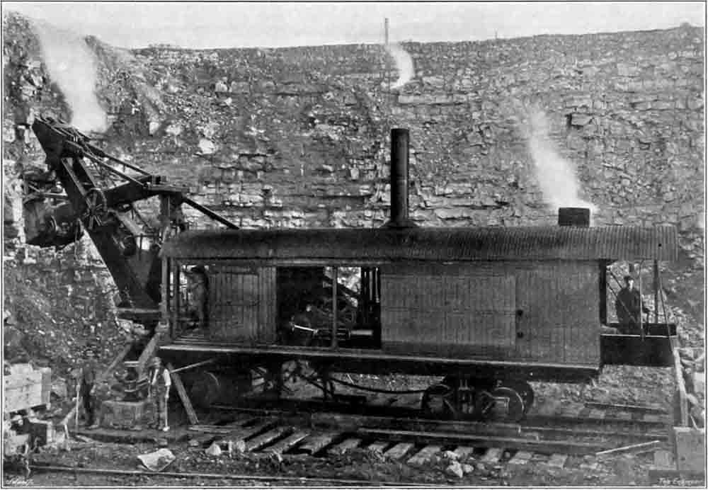
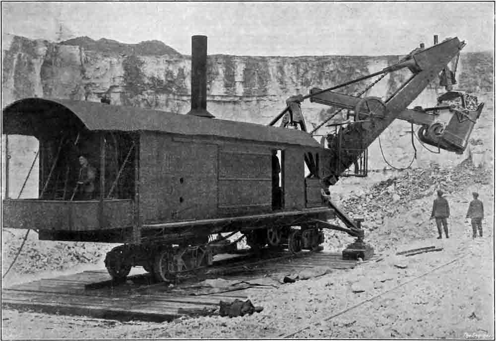
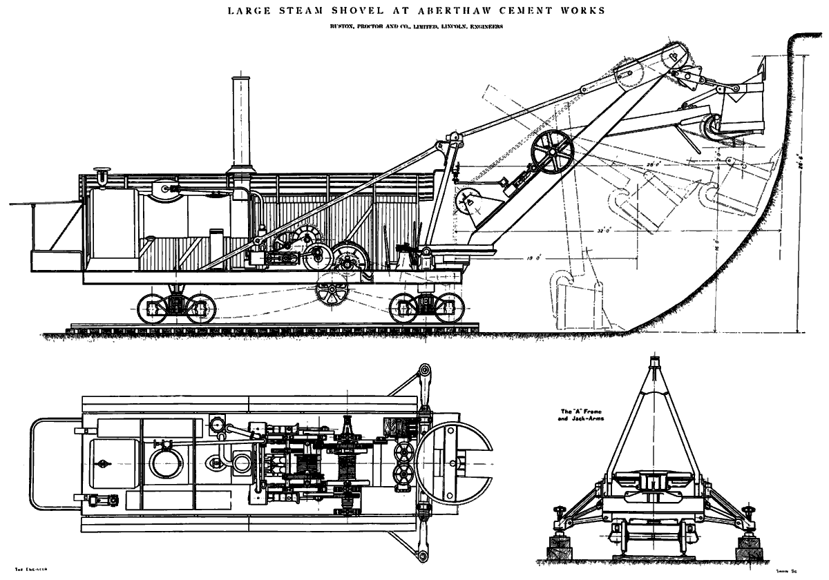
We also give the general composition of the Aberthaw marl or shale, and it will be realised how that by a proper adjustment of the proportions the correct mixture for Portland cement manufacture may be arrived at. In fact, at Aberthaw the raw material is an argillaceous limestone having a composition which is practically ideal for making high-class Portland cement. A quarry is in course of being opened out immediately adjoining the works. The deposit is exceedingly hard and by no means easy to quarry by hand labour. Indeed, had this course been pursued the cost would have been prohibitive, and the very wise decision to adopt a steam digger was come to (Note 3). The machine in operation was supplied by Ruston Proctor and Co., Limited, of Lincoln, who have devoted their attention for years to this class of work, and it is an excellent example of mechanical construction. We have already described it in our issue of April 9th (Note 4), but we may here repeat that the machine has a digging capacity of 100 tons per hour or more, and that it has been in daily operation for months with but little cost for repairs. It says not a little for the quality of the material and workmanship entering into its construction that during the whole of the time it has been at work it has not been necessary to renew any of its coiled suspension springs nor any of the links of its various chains, and that the cost for repairs has been practically negligible.
When first put to work this machine excavated the rock itself but latterly a great improvement has been made and the work of excavation rendered much more easy by the introduction of blasting operations. Vertical holes are driven into the rock from the surface near the face of the excavation by means of a specially designed drop drill which was supplied by the Cyclone Drill Company of Orrville, United States of America. Blasting charges are introduced into a series of these holes, which are taken down some 30ft. to 40ft., and fired, with the result that the rock is not only loosened and made to fall forward in the direction of the excavator, but it is broken up so that the digger has little more to do than pick up the stones. To this method of quarrying we hope to return at a later date but meanwhile we may say that the cost of drilling the holes and blasting amounts to about 4.835d. per ton of cement made, and that the total cost of blasting, excavating the material and delivering it to the crushers, including wear and tear of trucks, locomotive and permanent way, amounts to 1s. 1.14d. per ton of cement manufactured (Note 5).
The choice of a proper site for the manufacture of Portland cement is a matter calling for mature consideration. It is not enough that the raw materials of the desired composition and quantity should be ready to hand, though naturally this is a most important point. There are certainly two other essentials without which it would be difficult to compete on anything like equal terms with rival firms which possessed them. One is the facility for getting coal or other fuel, and the other is the facility for dispatching the cement when it is once made. In all three respects the works at Aberthaw may be said to be most fortunately situated. Raw material is, as we have shown, present in abundance and of ideal composition; the works are close to coal fields (Note 6) producing fuel which is suitable for use in rotary kilns; two lines of railway - the Vale of Glamorgan and the Taff Vale - pass in immediate proximity to the site, and to both of them there is direct connection by sidings, and finally the harbour at Aberthaw, which is on the Bristol Channel, provides means for the ready dispatch of cement by water (Note 7). Nor do the foregoing exhaust the advantages enjoyed by the site, for an abundant supply of water is afforded by the Rivers Kenson and Thaw, the former of which actually passes alongside the power house and flows into the latter only a short distance further on (Note 8). The position chosen could, therefore, hardly be improved upon, and when it is said that the works have been laid out with great care so that the raw materials as they pass through them are subjected to the minimum of handling, and the machinery installed is of the highest standard throughout, it can be well understood that the company is in a position to manufacture cement of the highest quality at a low cost.
The raw material as it comes from the quarry face is very nearly accurately proportioned for cement making. There is, however, at present a slight excess of clayey matter or marl and this is removed in the following manner: The stone and marl are brought from the quarry face in 6½-yard side-tip wagons running on standard gauge lines and drawn by a tank locomotive of the contractor's type. The latter hauls them up a short incline to a feeding platform arranged above two stone crushers. The wagons are discharged on to a fan-shaped grid formed of steel rails arranged so that they radiate up, from the entrance to the feeding shoot, to the level of the railway. The distance between each rail of the grid is therefore, greater at the top than at the bottom, and a portion of the surplus marl falls through the wedge-shaped spaces formed between the rails and is taken away in trucks. This marl is being employed to raise the level of an area of land adjoining the site of the works but on the far side of the River Kenson.
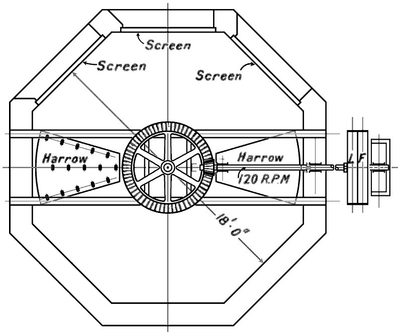
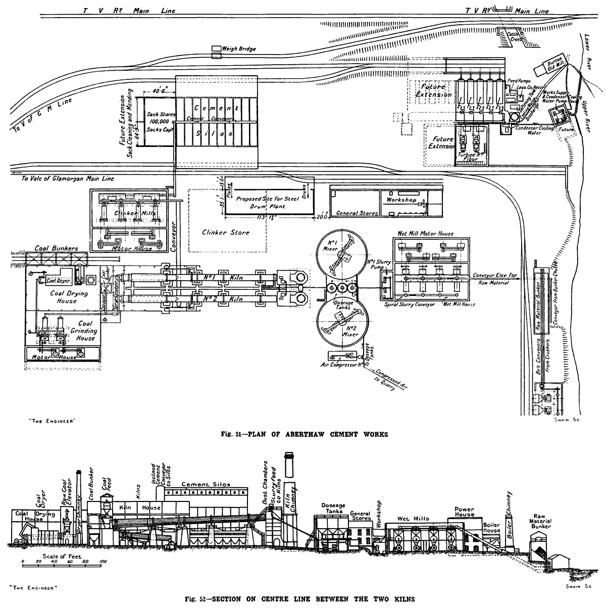 Figures 51 and 52 Figures 51 and 52 |
The plan and section shown in Figs. 51 and 52 will help to make the following description clear. We are indebted for the drawings from which these engravings were made to the courtesy of Mr. Day who, as we have said above, designed and laid out the whole works. We may mention here that in the course of this article it is proposed only to give the names of the makers of machines not made by Messrs. Newells. If no name be mentioned it is to be taken that the machines were supplied by the Misterton firm.
There are, as has been said, two stone breakers. These are of the jaw type with a feed opening 36in. by 22in., and they are designed to deal with 80 tons of stone per hour, and to break it up to a size sufficiently small to feed into ball mills. The crushers are both driven from a countershaft, which is in its turn driven by a 100 horse-power motor running on a 3000/3300-volt three-phase 50-period current at 580 revolutions per minute. This motor was supplied by the Allmänna Svenska Elektriska Aktiebolaget (Note 9). The crushed material as it is discharged from the jaw breakers is delivered on to two conveyor belts, one for each machine, and is raised to the top of a stone store which is divided into six compartments, into any one of which the broken raw materials can be delivered by means of delivery carriages (Note 10) which run on rails the length of the building. The stone store is designed to hold 1000 tons. Each compartment is provided at the bottom with a delivery shoot which can be opened and closed so that stone may be drawn from any of the compartments at will, this permitting of variation of the mixture as required (Note 11). The delivery from these shoots is on to a horizontal conveyor, which in its turn delivers the stone and with it, of course, a certain amount of marl, on to a tray conveyor elevator running up to the top of a two-storey building which contains the grinding machinery.
The grinding of the stone is carried out in two stages, first in ball mills and then in tube mills. There are four of each type of mill, the ball mills being arranged on the upper floor and the tube mills on the lower floor. We shall have occasion to refer more particularly to the form of the jaw breakers and these tube mills, as also to that of the remainder of the machinery later on, and for the present we will only consider the passage of the raw material through the works until it becomes finished cement, without going into the details of the various machines. A view of the grinding raw material house during construction is given in Fig. 53, and an interior view of the finished building in Fig. 54.
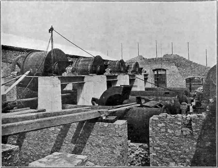 Fig. 53: Rawmill building under construction, from the south end. The mill piers are concrete, but the building is of rubble masonry. The slurry pumphouse is in the foreground. Fig. 53: Rawmill building under construction, from the south end. The mill piers are concrete, but the building is of rubble masonry. The slurry pumphouse is in the foreground. |
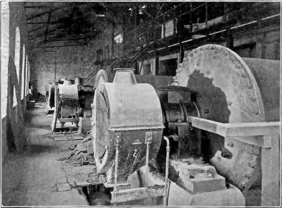 Fig. 54: Inside the rawmill house, from the other end The ball mills are above to the right. To the left are the tube mill outlet ends, and the slurry collecting screw runs under the floor. Fig. 54: Inside the rawmill house, from the other end The ball mills are above to the right. To the left are the tube mill outlet ends, and the slurry collecting screw runs under the floor. |
The rate of feed to the ball mills is controlled by means of a revolving table (Note 12) provided with a central lifting sleeve, which allows more or less stone to descend on to the table from an overhead hopper, which is kept supplied by means of the conveyor already mentioned. As the stone is fed into the mill by means of a diverting arm arranged just above the revolving table a certain amount of water is added. The discharge from each ball mill descends to its corresponding tube mill, which is arranged on the lower floor immediately beneath it. The slurry coming finally from the tube mills has been so finely ground that when it is dried only some 6 to 7 per cent. remains on a 180 by 180 sieve (Note 13). All the eight mills are motor-driven, one motor being provided to work each grinding unit - that is to say, a ball mill and a tube mill. The motors are arranged in another portion of the building which is entirely separated from the grinding mills by a brick wall.
We may here make a digression and remark that a feature of the works is the care which has been devoted to the electrical apparatus. As far as has been possible, all the motors and their controlling gear have been installed in separate rooms, which are kept as dust-tight as possible, and are entirely shut off from the machines they are driving. The wisdom of this course will make itself amply evident in freedom from repairs and breakdowns. We feel bound, moreover, to say that though a large proportion of the electrical apparatus is of foreign origin, the whole is of excellent quality and design, and is evidently doing its work well. We must confess, however, to a feeling that it would have been more pleasing could the whole of the works have been provided with British machinery, as is the part of it which is engaged in the actual production of cement. There is no machine or apparatus in the electrical equipment, or in the prime movers driving the moving parts, which could not have been made, and made well, by British manufacturers.
- o - O - o -
To return to the motive power of the grinding mills. There are in all four three-phase 50-period motors working on a 3000 to 3300-volt circuit and designed to develope 350 horse-power at 580 revolutions per minute. These motors were, like those for the stone breakers, supplied by the Allmänna Svenska Elektriska Aktiebolaget. Each drives by two belts on to two lines of countershafting which run through the partition walls into the grinding house. All the switches and other controlling gear are arranged in dust-tight cases, and are in such places that they are readily manipulated and kept clean. The precaution of having everything in a separate room kept as free from dust as possible renders the task of cleaning all the easier. An interior view of the motor house is given in Fig. 57 in our Supplement.
 Fig. 57: Interior view of the rawmill motor house. Fig. 57: Interior view of the rawmill motor house. |
The delivery from each of the tube mills falls into a horizontal trough in which works a worm conveyor (Note 14), whereby the slurry is led along to a pump house containing two vertical three-throw ram pumps. These pumps are driven by a motor working on to a countershaft, there being fast-and-loose pulleys for each pump, so that either or both may be worked. The motor, which was supplied by British Thomson-Houston Company, Limited, Rugby, is of 30 horse-power. These pumps are designed to lift the slurry up into three doseage tanks, arranged between and at a higher level than two large circular mixing tanks. As a matter of fact, the three doseage tanks are not at present being used, it being found quite possible to keep the "mixture" correct by means of the mixing tanks alone, but they were provided as a precautionary measure, and may be here described in some detail. The three tanks stand side by side. They are made of reinforced concrete, and are circular in plan, the top portions having parallel sides and the bottom portion being in the form of an inverted cone. Each tank is designed to hold 80 tons of slurry (Note 15), and each is provided inside near its bottom with a series of nozzles through which air can be blown under pressure. The pipes connecting the three doseage tanks together are so arranged that any one tank, if found to be too high or too low in lime, can be interconnected with one of the other tanks having a suitably lower or higher lime content. As we have said, however, these tanks are not at the moment being used, since it has been found that with the raw materials as they are at present coming from the quarry, it has been quite easy to keep the mixture correct by using the large mixers only; but the doseage tanks are there as an additional precaution should they at any time become necessary, and an air compressor made by the Ingersoll-Rand Company is installed in a house near by to supply the compressed air. A view showing the three doseage tanks and one of the large mixing tanks is given in Fig. 55 in our Supplement.
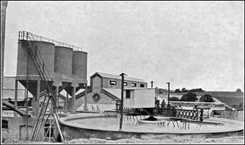 Fig. 55: Dosage tanks and slurry mixer. Fig. 55: Dosage tanks and slurry mixer. |
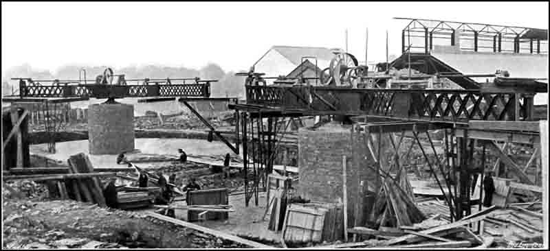 Fig. 64: Slurry mixing tanks under construction. In the background is the rawmill house: the structure on the top accommodated the overhead shuttle conveyor feeding the rawmill feed bins. Fig. 64: Slurry mixing tanks under construction. In the background is the rawmill house: the structure on the top accommodated the overhead shuttle conveyor feeding the rawmill feed bins. |
It is, of course, well recognised that it is of vital importance that the mixture of the slurry should be kept absolutely correct, or good results cannot be hoped for. Indeed, it must not be allowed to vary more than a fraction of 1 per cent at any time, and we understand that at Aberthaw this condition is accurately fulfilled by controlling the raw material before it enters the raw mills.
The slurry therefore is now pumped direct into one or other or both storage tank mixers which are large circular reinforced concrete tanks, each 66ft. in diameter and 12ft. deep. Each tank can hold enough slurry to make 600 tons of cement, and since the output of the works, when working to their full capacity, is about 330 tons per day, it follows that the two tanks together hold enough for between three and a-half and four days' supply. Each tank has a central brick column, on which is pivoted so as to revolve on ball bearings a two-armed cantilever lattice girder. This girder or bridge derives its motion from skeleton paddles which depend from the bridge, and which are themselves revolved by an electric motor deriving its supply of current from overhead wires. This motor is of 20 horse-power, three-phase current, and was supplied by British Thomson-Houston Company, Limited. The paddles dip down nearly to the bottom of the tank, and the combined motion of the bridge and paddles—which revolve at a faster rate than does the bridge—ensure that the mixture is kept continuously agitated and homogeneous in composition throughout. A view of the two mixing tanks during construction is given in Fig. 64. From the tanks the slurry gravitates to two sets of three-throw pumps, which are housed in a chamber formed beneath the doseage tanks.
In order to ensure that the amount of slurry fed into the kilns shall be of a regular and known quantity the following arrangements have been made by Mr Day. Each set of pumps has been designed to discharge rather more slurry than is required to provide the full amount of material for one kiln, and each pump delivers into a separate tank fixed on a platform above the feeding end of its particular kiln. These tanks have overflows so that the head of slurry may be kept constant, the surplus flowing down the overflow pipe back to the mixing tanks. For the further action of the feeding arrangement, we cannot do better than quote the actual words which Mr. Day used in describing it in a paper which he read last year before the South Wales Institute of Engineers. He said: "This [the overflow] gives a definite fixed head or pressure on the outlet pipe, and consequently a regular feed (Note 16). The feed is varied by the burner according to the working of the kiln by means of a plain sluice valve fitted with an indicator, which shows on a quadrant the exact amount the valve is open, and consequently the rate of flow. The slurry falls [from the tank] into a large cast iron cup, the outlet of which can be stopped. The quantity at any time passing can be instantaneously checked by ascertaining the number of seconds required to fill the cup to an overflow weir provided in the cup".
We have now arrived at the stage when the properly proportioned slurry is fed into the kilns. We shall refer more particularly to the construction and driving of the latter later in these articles, but we may say here that there are two of them arranged side by side—see Figs. 56 and 62 in our Supplement. Each has its own dust-arresting chamber and its own chimney. Each of the latter is circular and 200ft. high with a top opening of 8ft. diameter, and both chimneys and dust chambers, which were the work of the Custodis Company, are good pieces of work. The kilns are 200ft. long and 9ft. in diameter for the major portion of their length, with an enlarged burning zone 10ft. in diameter. A section of one of the kilns is given in. Fig. 66, and two views taken during erection are shown in Figs. 63 and 65. The kilns are fired with powdered coal, and to the coal-drying, grinding and feeding mechanisms we shall also refer later. The burnt clinker falls into inclined coolers through which is sucked by a fan a current of cold air, while just before the clinker leaves the cooler a small jet of water is played on to it. On issuing from the coolers the clinker falls through a circular riddle—which retains any large lumps which may have come through—on to a travelling plate conveyor. At this point the necessary quantity of gypsum is added (Note 17). The conveyor either discharges the burnt clinker and gypsum into the hopper of an elevator leading to the upper part of a two-storey building which contains the grinding machinery, or it may discharge it on to the ground reserved for clinker storage.
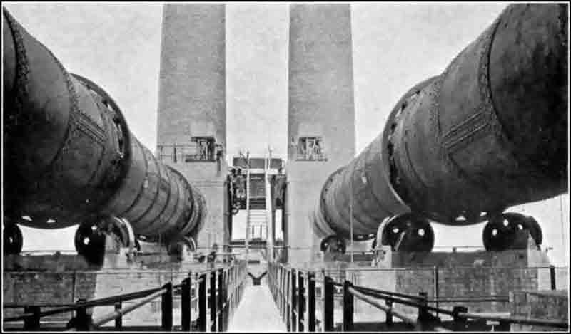 Fig. 56: View along kilns from the firing platform (from the south). Fig. 56: View along kilns from the firing platform (from the south). |
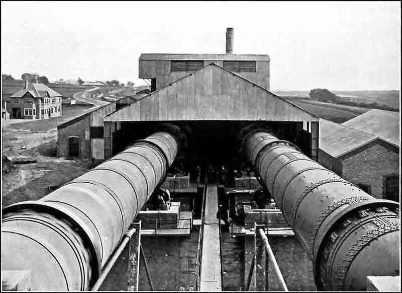 Fig. 62: View along kilns from the feeding platform (from the north). Evidently No 1 (right) is stopped, and No 2 is running. Fig. 62: View along kilns from the feeding platform (from the north). Evidently No 1 (right) is stopped, and No 2 is running. |
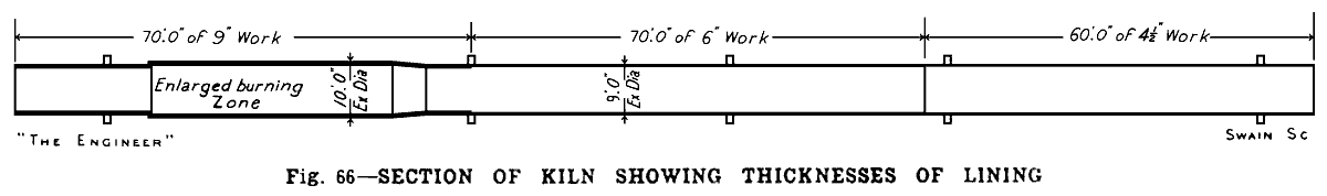 | |
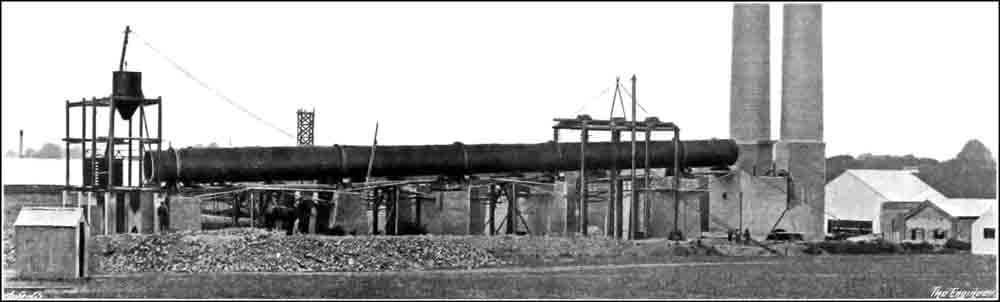 Fig. 63: One of the rotary kilns (No 2) being erected. The No 2 fine coal hopper is also in place. Fig. 63: One of the rotary kilns (No 2) being erected. The No 2 fine coal hopper is also in place. | |
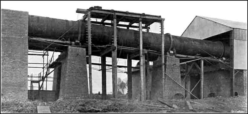 Fig. 65: Rotary kilns showing riding rings and carrying rollers. View from the west of the cold ends: No 1 was evidently the last to be installed. Fig. 65: Rotary kilns showing riding rings and carrying rollers. View from the west of the cold ends: No 1 was evidently the last to be installed. | |
The grinding equipment consists of four ball mills and four tube mills arranged in two floors in one building, so that each tube mill comes directly under its corresponding ball mill. A view showing the building in course of construction with the various mills in position is shown in Fig. 58 in our Supplement. The eight mills are driven by four motors, which are an exact counterpart of the motors which drive the raw materials mill, and which are contained in a compartment of the grinding house, but completely cut off from the mills by a brick wall. All the motors are on the ground floor and each drives by belts on to two countershafts, the upper of which drives a ball mill and the lower a tube mill. The motors are all of 350 horse-power and they were supplied by the Allmänna Svenska Elektriska Aktiebolaget. We shall refer in more detail to the grinding mills later. Meanwhile we may say that the plant has been designed to grind the cement down to such a degree of fineness that there is only a residue of 7.5 per cent. on 180 by 180 mesh sieve. The ground cement, as it is delivered by the tube mills, is taken by a travelling band conveyor and delivered into the hopper of an elevator, which lifts it to the top of the building and discharges it on to a second belt conveyor which runs up a covered-in flying bridge connecting the grinding house with the top of the cement silo. The angle at which this bridge is arranged is 27 deg. (Note 18) from the horizontal. Arrived at the top of the silo, the cement is transferred to a third band conveyor which is horizontal and which traverses the whole length of the building and can discharge it by means of a travelling throw-off carriage, which runs on rails laid on a gantry carried on columns resting on the walls of the main structure, into any one of the twenty compartments or bins into which the building is divided.
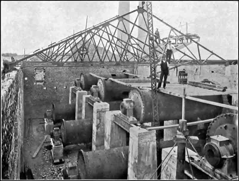 Fig. 58: View of the finish mills under construction. Fig. 58: View of the finish mills under construction. |
The silo building is constructed of reinforced concrete and is a fine example of work of this character. Each of its twenty bins is designed to hold 500 tons, so that the total capacity is 10,000 tons, which permits of a storage of some five weeks with the works operating to their fullest extent. The building, which is situated between two sidings communicating with both the Vale of Glamorgan and the Taff Vale railways, covers 6700 sq. ft. of ground and rises to a height in the centre of 77ft. It is supported on fifty-five concrete columns, eleven of which measure 36in. by 24in. in cross section, the remaining forty-four being 24in. square. The roof, which is of corrugated iron laid on felt boarding is alone not of reinforced concrete. Each of the twenty bins has a width of 10ft., a length of 30ft., and an average depth of about 45ft. The bottoms are hoppered at an angle of about 60 deg. so as to form a V-shaped trough, and each bin is provided with four outlets each fitted with a sliding gate. There are thus no fewer than eighty points from which cement may be drawn off as required.
The headroom below the lowest point under the bins is 6ft., and, as the whole of the floor is clear, saving for the supporting columns, there is a large space available for laying out and packing the cement. The loading floor is extended on either side of the building for a distance of 22ft. so as to form platforms for the two sidings, both platforms and sidings being entirely covered in by lean-to roofs. The platforms are long enough to permit of twelve trucks being loaded at one time.
Some further particulars of the building will doubtless be of interest. The division walls between the bins are 5in. thick and they have vertical beams spaced at 6ft. centres. These beams are supported by 1¼ in. diameter tie-bars arranged at varying pitches, being spaced at 9ft. centres at the bottom and at 11ft. centres at the top. The longitudinal walls taper in thickness from 8in. at the base to 6in. at the top, and are made sufficiently strong not to require any vertical beams or tie rods. The aggregate used for the concrete was limestone obtained locally and crushed on the site. The reinforcement consisted of indented steel bars. The concrete mixture used generally throughout the building was of the strength of 1-2-4, but the columns were given a greater proportion of cement. A machine mixer was employed. No scaffolding was used for erecting the building, the work being done from platforms fixed to the centering and tie rods. The quantities of materials required in the construction, which we may mention was carried out by Messrs. Lewis Rugg and Co., of Westminster, were 380 tons of cement and 109 tons of steel. We have dealt at some length with this structure as it forms quite a feature of the works both in design and construction. It is shown during construction in Fig. 59, and completed in Fig. 61 of our Supplement.
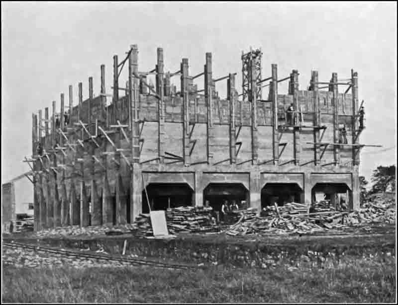 Fig. 59: Cement silos under construction. View from the north. Fig. 59: Cement silos under construction. View from the north. |
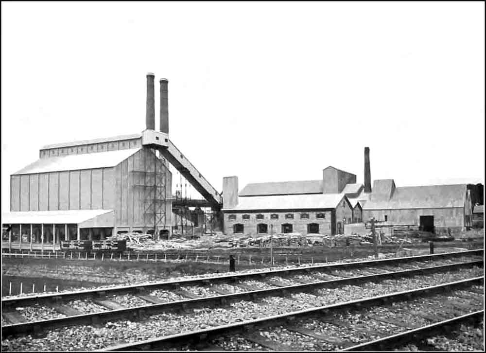 Fig. 61: Completed cement silos to the left in a northeast view of the plant taken from the Vale of Glamorgan trackside. Centre view is the finish mill house and the coal preparation plant is to the right. Fig. 61: Completed cement silos to the left in a northeast view of the plant taken from the Vale of Glamorgan trackside. Centre view is the finish mill house and the coal preparation plant is to the right. |
Although we propose to deal in detail with the coal-grinding and handling plant in a future article, a few words may now be said regarding the coaling arrangements generally. The coal is brought on to the site on two sidings, which are quite independent of the cement sidings already referred to, and one of which is taken to the power-house and the other to the coal-grinding house. Near the latter there is a large area of land devoted to the storage of coal. This is of considerable advantage because it enables the firm to buy coal in large quantities when it is cheap and to store it on its own land. The importance to the cement manufacturer of having cheap coal may be realised from the fact that for each ton of cement produced a quarter of a ton of coal is burnt in the kiln. For a works of this size, therefore, when in full operation, some 500 tons of coal are required per week for the kilns alone. Having regard to the large quantity of coal which it would use, the company went into the question of what it would cost to handle the fuel by various methods. It was found that if dealt with by hand the cost would be not less than about £800 per annum. It was therefore decided to purchase a number of 12-ton hopper-bottomed wagons which could be run over underground bunkers and discharged. Alongside the coal-grinding house are arranged four such bunkers, each of which contains 40 tons. These bunkers are designed to deliver the coal automatically into a band conveyor, which in its turn discharges into the feed hopper of an elevator. The latter raises the coal and feeds it into the hopper of a pair of crushing rolls, in which the large lumps are broken up.
As delivered to cement works, coal always contains moisture, the amount varying in degree up to some 10 per cent. If stored in the open small coal may absorb more than this should the season be rainy, as the past winter has been. In order to grind it satisfactorily, coal should not certainly contain more than 2 per cent. of moisture, and to reduce the moisture to this figure special means of drying have to be provided. The dryer at Aberthaw is of the inclined revolving tube type heated by a coke fire. It is driven by an electric motor of 20 horse-power, which was supplied by the British Thomson-Houston Company. The dried coal is taken by a conveyor to an elevator, which lifts it to a conveyor running over the tops of hoppers above two ball mills. Coal is by no means easy to reduce to a fine powder owing to its soft, silky and flaky nature, but the combination of ball mills and tube mills perform the work adequately, and this is the combination employed at Aberthaw, where the coal is ground finely enough to show a residue of not more than 5 per cent. on a 100 by 100 sieve. The ball mills are on one floor and the tube mills are on the floor below it. Each pair of ball and tube mills is driven by belt by a 150 horse-power motor supplied by the Swedish firm already mentioned, these motors being contained in a portion of the building which is entirely separated from the grinding machinery. The ground coal discharged from the tube mills is taken in a spiral conveyor to an elevator, which raises it so that it can either be delivered to a large coal storage bunker or else to one of the two feed bunkers which are situated one over each of the two rotary kilns at the firing end. The remaining illustration in our Supplement Fig. 60 gives a general view of the works. In the middle distance on the right is seen the dwarf chimney of the electric power-house, to which we shall refer in our next article.
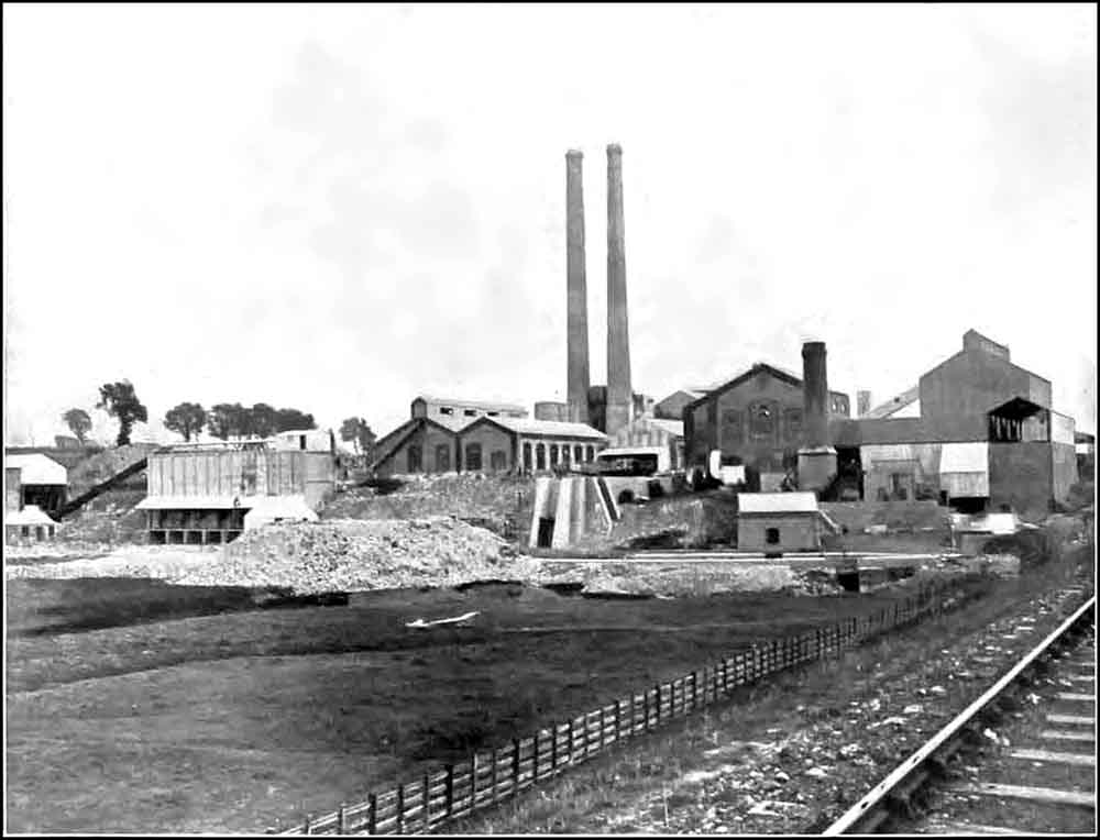 Fig. 60: Southward view of the plant from the embankment of the Taff Vale railway, north of the bridge over the River Kenson. The mill leet runs left to right across the picture, running behind the pile of waste shale being used to "raise the level" of the marshland, and in front of the steep bank. Across the leet on the left is the raw material bunker, with a sloping conveyor feeding the rawmill behind. The small building to the right is the pump house abstracting water from the leet to feed the power house. Fig. 60: Southward view of the plant from the embankment of the Taff Vale railway, north of the bridge over the River Kenson. The mill leet runs left to right across the picture, running behind the pile of waste shale being used to "raise the level" of the marshland, and in front of the steep bank. Across the leet on the left is the raw material bunker, with a sloping conveyor feeding the rawmill behind. The small building to the right is the pump house abstracting water from the leet to feed the power house. |
- o - O - o -
Attention may now be directed to the power plant, which is of considerable interest, though unfortunately much of the machinery it contains is not of British manufacture. A glance at the plan Fig. 51 ante, will show that the power house is close to the bank of the river Kenson. It will have been gathered by the foregoing description that the whole of the machinery throughout the works is driven electrically—in fact, the only steam engines at work are those used on the steam digger, the drill and the locomotives. This means that a large electrical central station had to be provided. Fortunately, the proximity of the two rivers and the consequent abundance of water, easily got, allowed of the employment of steam turbines. Steam is obtained from five Lancashire boilers, 30ft. long and 8ft. 6in. internal diameter, supplied by Tinker, Shenton and Co. These are fitted with Bennis stokers, the hoppers of which are each separately fed by automatic elevators, which deliver the coal from bunkers below the siding, into which it has been discharged from the hopper-bottom wagons above referred to. The boilers work at a pressure of 180 lb. to the square inch and are fitted with Sugden's superheaters in the down-take flues. The final temperature of the steam on leaving the superheaters is somewhere in the neighbourhood of 600 deg. Fah. Between the boilers and the chimney is a Green's economiser with 640 tubes, which raises the temperature of the feed-water to 150 deg. Fah. Quite a short chimney is employed, it being only 55ft. high, and draught is provided by an induced draught fan and compressed air on Bennis's system. The boiler feed is pumped into the boiler by means of a three-stage centrifugal pump, which is driven by a high-speed steam turbine of the Pelton wheel type. This combined set, which runs at 3000 revolutions per minute, was supplied by Sulzer Bros., of Winterthur, and it has we understand, worked exceedingly well. In case of its breakdown, however, a single ram pump, made by J. P. Hall and Sons, Limited, Peterborough, has been installed. The turbine feed pump exhausts into a condenser fitted in the hot-well tank, and as the latent heat of the steam is thus recovered the combination is found to be very economical. The river water, it is not extraordinary to find, seeing that it comes from limestone country, contains 30 deg. of hardness, and consequently the make-up water, which amounts to about 10 per cent., has to be softened, a Lassen and Hjort apparatus being installed for the purpose.
The generating machinery consists of two 1500-kilowatt turbo-alternators—see Fig. 67. Both the turbines were supplied by Escher, Wyss and Co. They are both of the Zoelly type. One of them drives a Brown-Boveri generator and the other a Siemens generator, both being direct-coupled. Both alternators are designed to generate three-phase 50-cycle current at 3000 to 3300 volts when running at 3000 revolutions per minute. One of these generators will furnish current sufficient to work one-half of the plant at present installed, that is to say, plant which is producing 1200 tons of cement per week. They are excellent machines in every way and are, we gather, working with high efficiency. The generators are kept cool by air circulation, a wet filter of the Balcke type being furnished for cleansing the air.
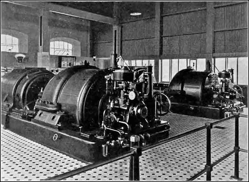 Fig. 67: The two 1.5 MW generators. Fig. 67: The two 1.5 MW generators. |
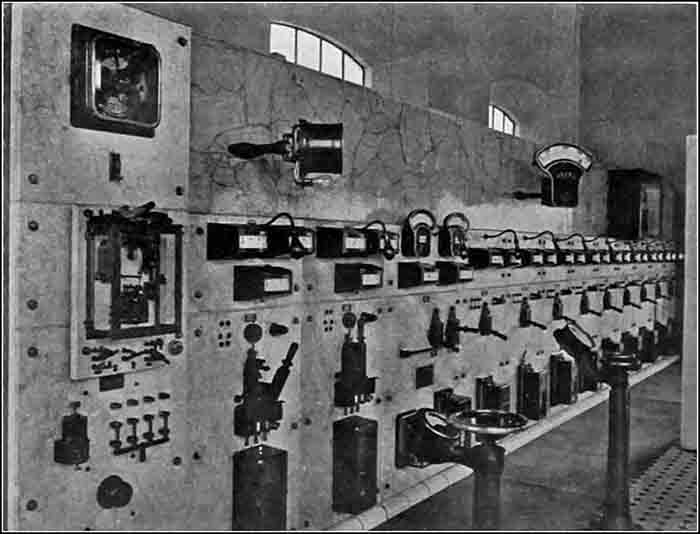 Fig. 68: The power house switchboard. Fig. 68: The power house switchboard. |
Each generator has its own condenser, which is arranged in a basement below the engine-room floor. The whole of the condensing plant was supplied by Escher, Wyss and Co. The condensers are of the counter-current surface type, and all the condenser pumps are of the rotary type. The circulating pumps are contained in a separate building, which is slightly nearer the river than is the power-house. Each is driven by a 40 horse-power Siemens motor. This power is only required at starting, as an arrangement has been made by which the outlet of the condensers is connected to a water seal at the same level as the pump-house. The pumps, therefore, only have to deal with the friction in the condensers and piping plus a short suction head. It is calculated that this arrangement ensures a saving of at least 200 tons of coal per annum. Each condenser has its own condensate pump and dry air pump and both are electrically driven. The condensate is returned direct to the hot well, over which is a Lea notch tank connected through a float tank to a Lea recorder. The latter not only indicates and records the total boiler feed, or steam consumption, of the plant, but also indicates and records continuously the quantity of water used. In this way not only can the rate of evaporation in the boilers at any moment be read, but also the total quantity over any period can be ascertained. In the house containing this instrument there is also a Sanders-Rehders CO2 recorder. We may here say that the system of record-keeping not only in the power-house but throughout the whole works is of the most detailed and useful character (Note 19). There is no process or part of a process of which the fullest records are not kept, and these records are not only of extreme interest but of the utmost value. Among other records kept are accurate figures regarding the power required per ton of output with varying degrees of fineness from the different units.
In the circulating pump-house are two Rees Roturbo pumps, each driven by a British Thomson-Houston motor. These are installed for providing a general water supply to the works, and for the purpose of arranging for a constant head of water a tank has been erected between the two kiln chimneys at a height of some 40ft. from their base. A large quantity of water is used in a cement works. The amount required to mix the slurry is considerable (Note 20), and in the Aberthaw Works advantage has been taken of a copious supply of water readily obtained to cool all the bearings of the mills, kilns and crushers with water and thus to economise lubricants.
The main high-tension switchboard—see Fig. 68—in the engine-room was supplied by the B.T.H. Company. It consists of thirteen panels controlling both generators and two 400-kilowatt oil-cooled transformers. From the board also run separate circuits to the crusher house, raw mill, clinker mill, coal mill, and to each kiln.
Throughout the whole works there are in all forty-two motors of various sizes down to 5 horse-power. Of these we give a list below with the names of the makers. Some of them have been alluded to in the foregoing:—
| No. | Output H.P. | Maker | Location |
|---|---|---|---|
| 8 | 350 | Allmänna Svenska Elektriska Aktiebolaget | 4 Rawmills |
| 4 Finish Mills | |||
| 2 | 150 | ditto | 2 Coal Mills |
| 3 | 75 | ditto | |
| 2 | 40 | Siemens Brothers' Dynamo Works, Ltd | 2 condenser water pumps |
| 2 | 20 | ditto | |
| 2 | 50 | British Thomson-Houston Company, Ltd | |
| 2 | 30 | ditto | Rawmill slurry pumps |
| ? | |||
| 3 | 25 | ditto | |
| 8 | 20 | ditto | |
| 5 | 9 | ditto | |
| 2 | 7.5 | ditto | |
| 3 | 5 | ditto |
There is also a certain number of motors smaller than this. All the motors above 50 horse-power are supplied with current at 3000 volts pressure For those below this power current at 220 volts is employed and this pressure is also used for the lighting. The kiln motors are each supplied direct from the switchboard in the power-house. Distributing boards made by the Union Electric Company, Limited, are fitted in the raw mill, clinker mill, and coal mill, so that each unit in each of these mills is under separate control and can be immediately stopped by pressing a button on the feed platform. All motors over 5 horse-power are of the pipe-ventilated type and all under that power are of the totally enclosed type.
There is in the engine-room in the power-house, in addition to the high-tension board already alluded to, a low-tension board which comprises ten panels with twelve power currents and nine lighting circuits. This board was supplied by Switchgear and Cowans, Limited.
The switch gear is all of the dust-proof type. The low-tension distributing hoards are contained in cast iron boxes mounted on brickwork bases. These boxes are dust-proof. All the cables are of the three-core paper insulated and lead-covered type and were supplied by the British Insulated and Helsby Cables, Limited. They are laid underground in brick ducts covered with cement slabs. There is one main cable trench carried throughout the works. Of the whole electrical equipment it can certainly be said that it is well designed and carried out. Ample power seems to have been everywhere provided. In a cement works where all classes of machines are subjected to very heavy usage this is a most important point.
In addition to the various contractors already alluded to we may say that the masonry buildings were erected by E. Turner and Sons, Limited, and A. G. Collins and Co.; the structural steel work was provided by Rees and Kirby, Limited, and Walker Brothers, Limited; and the conveyors and elevators were jointly supplied by Ernest Newell and Co., Limited; Babcock and Wilcox, Limited; Fraser and Chalmers, Limited; and the New Conveyor Company, Limited.
A description of a cement works is not complete without some reference to the testing arrangements, and at Aberthaw these are of a most elaborate kind. Every device and machine necessary for making analytical tests of raw material and finished cement and for carrying out physical tests of every possible description have been provided. The laboratory is a detached building in which the various investigations are carried out in separate rooms, the whole department being under the able control of Mr. O. J. Corelli (Note 21), who was good enough to carry out numerous tests for our benefit. In all cases the samples showed very good results indeed, far above those required by the British Standard Specification. We have also been provided with copies of analysis of the cement and of tests carried out by independent experts. These we give below:—
| Analysis of "Druid Brand" Cement made by the Aberthaw and Bristol Channel Portland Cement Company. | |
| % | |
| Silica, SiO2 | 25.38 |
| Insoluble residue | 0.22 |
| Alumina, Al2O3 | 3.73 |
| Oxide of iron, Fe2O3 | 2.43 |
| Lime, CaO | 65.26 |
| Magnesia, MgO | 1.03 |
| Sulphuric anhydride, SO3 (Note 22) | 0.56 |
| Loss on ignition (CO2 + H2O) | 1.18 |
| Alkalis and loss | 0.21 |
| Total | 100.00 |
| Physical tests and other particulars. | ||
| Nature of Test | Druid Brand | British Standard Specification, minimum requirements |
|---|---|---|
| Neat cement:— average of six briquettes: | ||
| At seven days | 608 lb. | 450 lb. |
| At twenty-eight days | 753 lb. | 674 lb. |
| 3 parts sand. 1 part cement:— average of six briquettes: | ||
| At seven days | 217 lb. | 200 lb. |
| At twenty-eight days | 340 lb. | 263 lb. |
| Note that in terms of modern EN 196 compression testing, this is 6 MPa at 7 days and 14.5 MPa at 28 days. | ||
| Fineness:— | ||
| Residue on 180×180 sieve | 9.5% | ≤14% |
| Residue on 76×76 sieve | 0.4% | ≤1% |
| Soundness:— | ||
| Le Chatelier expansion | Nil | ≤10mm. |
| Specific gravity | 3.160 | ≥3.10 |
| Hydraulic modulus | 2.54 | ≥2.0, ≤2.85 |
It will be appreciated from these figures that the Aberthaw cement is of excellent quality, nor are its full properties expressed by the foregoing. The pat tests also give very good results; indeed, we believe that no single failure has ever been experienced. Throughout the works there are numerous cases of brick walls having been served with a thin rendering of cement and sand. We examined several of these and in no case could any hair cracks be observed.
In conclusion, we desire to express our thanks to the directors of the company for permission to visit and describe these interesting works and to Mr. B. J. Day, Mr. W. A. Brown, and Mr. O. J. Corelli for courteous assistance in the preparation of this article.
In a future article we propose to discuss in more detail the various cement making machines used in these fine works, which machines, it will be remembered, were all made by Ernest Newell and Co., Limited, of Misterton.
CEMENT MACHINERY AT THE ABERTHAW WORKS, &c.
In the three preceding articles we have given a general description of the works at Aberthaw of the Aberthaw and Bristol Channel Portland Cement Company. We now propose to refer in more detail to the various machines which are in operation there and which have all been supplied by Ernest Newell and Co., Limited, of Misterton, near Gainsborough. We shall also take occasion to describe other machines which are used in cement manufacture and which this firm is prepared to supply, so that the present article may form a complete compendium of the cement-making machinery constructed by it. Messrs. Newells have, as we have already said, specially laid out their works to manufacture Portland cement machinery, and they have been most successful in their efforts. The firm started business with a full knowledge of what it had to face in the way of competition from abroad. It realised to the full what was the hold which continental firms had obtained on the British market, yet it was confident in its ability to hold its own, and one cannot but admire the pluck of Mr. Ernest Newell, the founder of the firm, for thus fearlessly entering the lists. For, it must be remembered, as we have pointed out before, that the makers abroad—especially the German makers—had busily spread and fostered the idea that unless foreign machinery, the makers of which had had so much more experience than our own people, were employed, failure must necessarily follow. Moreover, they were ready to equip works in their entirety. Then, again, foreign rivals were prepared to cut prices almost to any extent so as to keep British makers out of the market. Yet, in spite of all this, Messrs. Newells have made a success of their venture, and no small proportion of this success is undoubtedly due to the excellent quality of the machinery they supply, and to the thorough study they have made of the various processes carried out in the manufacture of Portland cement. The importance of this last attribute is very great; in fact, it is paramount. Unless our makers have an exact knowledge of the raw materials employed and of how these materials will behave under varying conditions, the hope of success is very small. Messrs. Newells have been investigating the problem of Portland cement manufacture in all its aspects for many years past, and they are now prepared, on being provided with an analysis of the raw materials, to put up works fitted with the machinery best suited to manufacture cement of the highest quality from those materials, provided, of course, that the latter are suitable for the purpose.
The firm naturally found at first that the task which it had set itself to perform was by no means easy of accomplishment, but it persevered, and as giving some idea of the measure of the results which have accrued, we may say that during recent years it has managed to obtain, in spite of keen German competition, a considerable share of the cement engineering business not only in this country but abroad. It has supplied several plants to the Associated Portland Cement Manufacturers, Limited, to the British Portland Cement Manufacturers, Limited, &c. For a branch of the latter company it has recently delivered a two-kiln plant for a works in Vancouver (Note 23). Then there are the Aberthaw Works, and we are prepared to say that it would be hard to beat any single item of the cement-making plant there. Finally, it is interesting to note, as a measure of the esteem in which this firm's products are held in this country, as contrasted with plant of German origin, that it informs us that it has during the last two years sold more cement machinery in the United Kingdom than all its German competitors added together have done (Note 24).
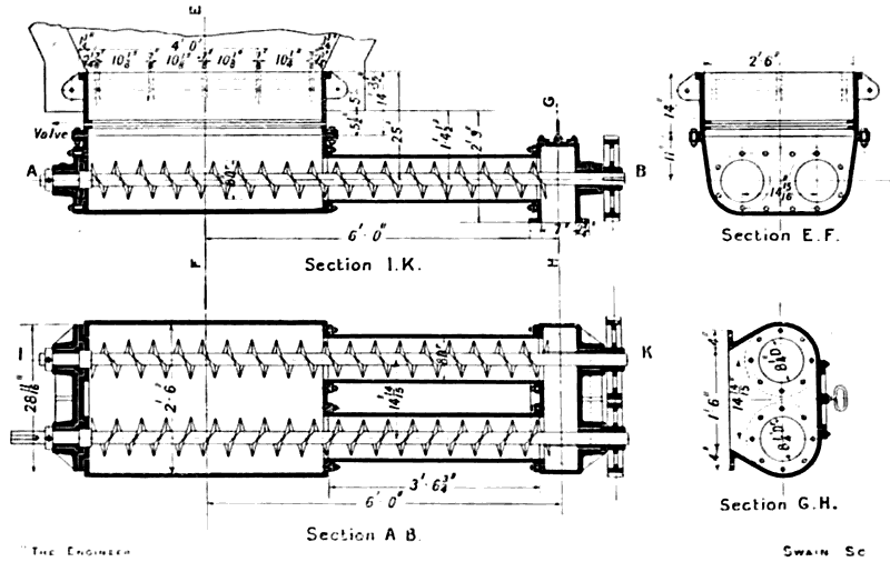
In describing the machinery at Aberthaw, it will be convenient to follow the same plan as in describing the works, and to deal with the various machines as they are employed in the course of the manufacture of the cement. First in order, then, come the two stonebreakers, which are of the swinging jaw or Blake type. This machine is illustrated in Figs. 69 and 70, and, as will be observed, it is of particularly solid construction. It has a feed opening measuring 36in. by 20in., so that it can take in large lumps of stone. The frame is made up in sections, which is, of course, convenient from the point of view of transport. The side frames are of cast iron thickened at the ends, and where the two shafts come, while the end pieces are of cast steel. The side frames are recessed where they join the end frames, and are tied together by heavy mild steel bolts which pass through from side to side. The general construction is very similar to that of other jaw breakers which have previously been described. The machine operates on the toggle principle, the pitman being raised and lowered by means of a cam on a main eccentric shaft. The pitman is made of cast steel and its head is water-jacketed. It is lined in the bearing with steel alloy, which is itself lined with white metal. The eccentric shaft is of mild steel and it is furnished with two heavy fly-wheels outside the frame. At Aberthaw the machines are provided with fast-and-loose pulleys and an outboard bearing. but if desired rope driving, as shown in Fig. 70, can be applied. The swinging jawstock is made of mild steel and it is faced with two corrugated reversible manganese steel jaw-plates provided with zinc backing. The end-piece opposite the swinging jaw is similarly furnished with manganese steel plates, which form the other face of the jaws, and are also reversible. The toggle plates and the grooved cushions in which they work are of manganese steel, and the former are provided with shrouds to prevent lateral movement, so that there may be no loss of power due to friction between the plates and the side frames and no injury to the latter by grooving. The toggle plates are also provided with large grease-boxes at each end to ensure a good supply of lubricant for the toggle joints. There is an arrangement by which the cushions can be withdrawn without the necessity for disturbing the pitman, jawstock or toggle block. There is the usual method for regulating the size to which the stone passing through the machine is broken by means of a toggle block and adjustable wedge, with which the readers of these articles are now familiar. Both toggle block and wedge are of cast iron and they are anchored by heavy bolts. A drawback rod with four rubber discs to furnish the necessary tension is provided with the object of ensuring that the jawstock shall swing back to its full extent on the return stroke and keep the various portions of the machine in their correct relative positions. A great deal of attention has evidently been paid to the question of lubrication, and, as will be seen, numerous sight-feed and other lubricators have been provided, all of them in accessible positions. In addition to these, there is, of course, the water cooling, so that it is most unlikely that these machines would ever have hot bearings.
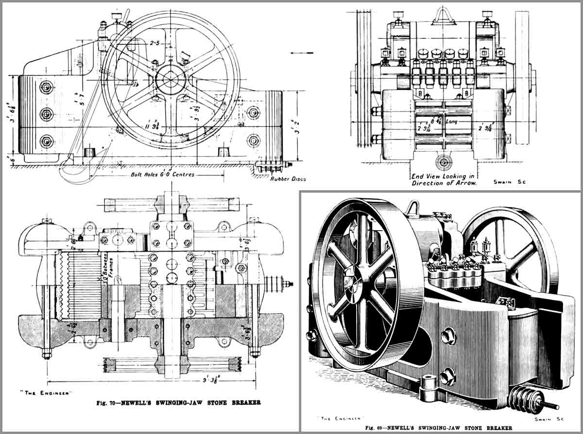 Figs. 69 & 70: Newells jaw crusher of the type used at Aberthaw. Figs. 69 & 70: Newells jaw crusher of the type used at Aberthaw. |
Each of the two jaw breakers at Aberthaw has a capacity of from 40 to 50 tons of hard limestone broken down to 2 in. cubes per hour, and each requires about 50 brake horse-power to drive it in full work. Both machines were in operation at the time of our visit, and both were operating most successfully. As a matter of fact, they were not set to break up the stone into very small pieces. and since there were no crushing rolls to follow them, it says much for the grinding mills—which we shall mention later.
| The article goes on to describe Newell's "Lion" gyratory crushers (not installed at Aberthaw). Refer to The Engineer, 14/5/1915 for details. |
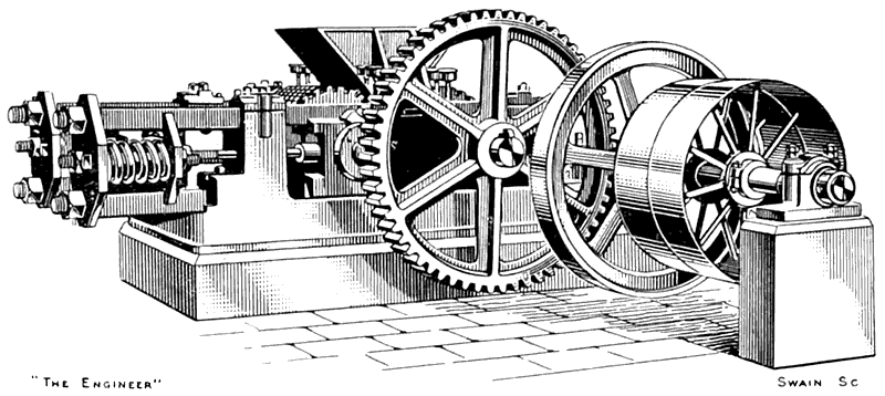 Fig. 73: Newells crushing rolls as used for coal crushing at Aberthaw. Fig. 73: Newells crushing rolls as used for coal crushing at Aberthaw. |
For breaking up lumps of clinker, shale, marl, chalk or coal, or for reducing the broken stone delivered from either type of stone breaker just described, Messrs. Newells supply crushing rolls such as those shown in Fig. 73. As illustrated, the rolls are provided with fast and loose pulleys, and this is how the machines are usually sent out, but if required friction clutches can be fitted. The driving shaft is furnished with a fly-wheel and the rolls are driven through spur reduction gearing. The two rolls are coupled together with coupling wheels with deep teeth so as to permit of adjustment apart of the rolls and hence of the size to which the material is crushed. Six sizes of these machines are made. Two of these have rolls 20in. diameter and either 16in. or 24in. long; in two the diameter is 28in. and the length either 16in. or 24in.; while the third pair have rolls 36in. long (sic) and again either 16in. or 24in. in length. The approximate respective weights of these six machines is 95, 100, 110, 118, 130 and 140 cwt. The centres or hearts of the rolls are of tough cast iron keyed to hammered steel shafts. The shells of the rolls may either be of chilled cast iron or of manganese, chrome, or high carbon steel, according to the work required of them, and they may be either smooth, fluted, corrugated, or toothed to suit the nature of the material on which they have to operate. They are fitted with spring cages, which are adjustable, so as to yield when stresses greater than those necessary to crush the material are encountered. Ordinarily the main frames are of cast iron, but rolled steel girder frames are supplied if required so as to facilitate transport or for other special reasons. It will be seen from the foregoing that Messrs. Newells are quite prepared to supply stone-breaking and crushing machines to suit any sort of material or to fall in with any special predilection (Note 25) on the part of the prospective user.
- o - O - o -
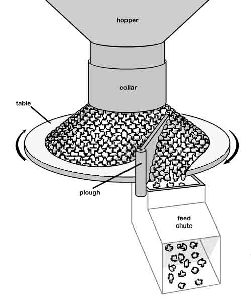
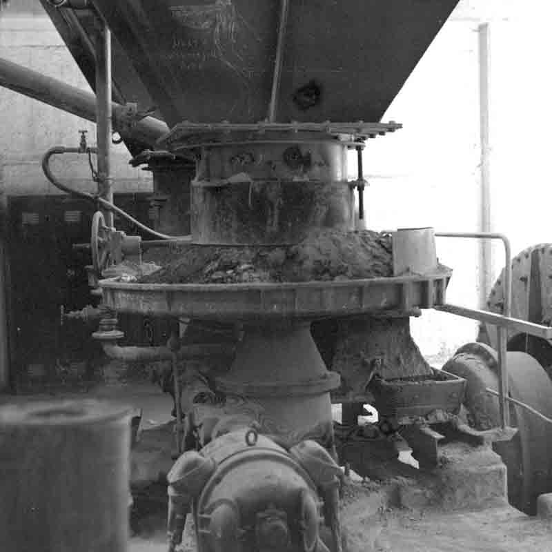
To return now to the actual machinery at Aberthaw. The broken stone as it comes from the two-jaw crushers falls on to two inclined band conveyors, which take it up to the top and deposit it in the raw material silos. These silos are, as a fact, constructed of ferro-concrete, but Messrs. Newells have frequently supplied silos made of mild steel for a similar purpose. For the process of grinding the stone there are four wet ball mills and four wet tube mills. The broken stone is brought up by a conveyor from the storage silos and is delivered into four mild steel bins arranged one over each of the ball mills. We have already referred to the automatic means of feeding these mills, but we may now give the following amplification of our former references. Newell's improved feeders consist of a rotating table, the edge of which projects over the feed hopper of the ball mill. The table is revolved by means of bevel gearing from the main shaft of the mill itself, and is surrounded by a casing. Over the centre of the revolving table is a vertically adjustable pipe connected to the feed bin overhead. The vertical height of this pipe can be varied. In its lowest position its lower edge is close to the table, so that no material can escape; in its highest position a quantity of stone in excess of that necessary for the full output of the mill can pass on to the table. The man in charge, therefore, has it in his power to arrange the quantity of feed to exactly the correct amount. The speed at which the table is revolved is slow, but it is high enough to permit of the material spreading over its surface. At the point where the table projects over the feed hopper of the mill a scraper is fixed, and is set at such an angle that the stone on coming against it is directed into the hopper.
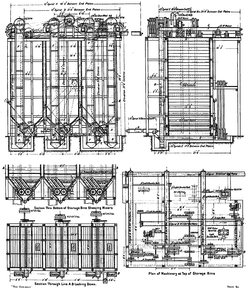
Ball and Tube Mills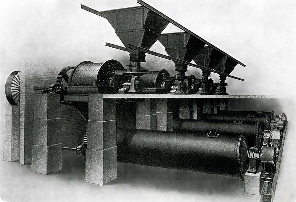 Fig. 74: The four Aberthaw ball-and-tube rawmill sets. Fig. 74: The four Aberthaw ball-and-tube rawmill sets. |
The arrangement of the raw material grinding mill grinding house is shown in Fig. 74. The four wet ball mills are of the sieveless type and are 9ft. internal diameter by 6ft. long. The body of each mill consists of a mild steel weldless tube ¾in. thick, while the end-plates are of rolled steel 1¼in. thick. The end-plates are secured to the bodies by 5½in. by 4½in. by ⅞in. welded angle flanges and 1in. rivets. Arranged round the internal circumference of the mill are chrome steel hunch-plates and the inner surfaces of the end-plates are also protected with chrome steel lining plates. the hunch-plates and end protecting plates being all held in position by bolts taken through to the outside. The feeding hopper is of cast steel, as are also the inlet and the driving naves. The drum shaft on which the mill rotates is of mild steel and is 10⅝in. in diameter in the largest part. The feed of the mill is in the centre of one of the end-plates through the hollow feeding nave. The outlet for the ground material is through a series of grids formed in the outlet end-plate, each grid being a separate steel casting covering an aperture cut through the end-plate of the drums. The grinding balls are of hardened forged steel, and their size varies from 4in. to 5in. in diameter. The mills are driven by machine-moulded spur gearing, and the main bearings, which are lined with white metal, are provided with grease caps. The driving pulleys are 8ft. in diameter and 22in. in the face.
Along with the stone the necessary amount of water is fed into the mills, each of which is surrounded by a drip casing constructed of mild steel plates and angles, and is carried on a supporting structure consisting of rolled steel joists and channels. The whole arrangement is well shown in the engraving, in which will be seen the feed bins, the revolving feed tables, and the four ball mills, each immediately over its corresponding tube mill, to which the discharge from the former flows by gravity. The ball mill is designed to reduce the raw material to the size of grits, which is the size best suited for feeding the tube mills.
The four tube mills are each formed of a welded steel body 27ft. long and 6ft. 2in. in diameter. The end covers, which are of cast steel and of the domed pattern, are provided with hollow trunnions and are lined inside with manganese steel. The mills are divided into two chambers of unequal lengths. The smaller chamber, which is at the feeding end, is lined with corrugated grinding plates, and is loaded with hard steel balls. In it any large nibs which may have passed through the ball mills are reduced to a size in which they are most efficiently dealt with in the larger or final grinding portion of the mill. The latter is lined with silex flint blocks and the grinding media are flint pebbles (Note 26). The partition between the two chambers is in the form of a grid with slots only large enough to permit of the passage of quite small grits. The trunnion bearings of the mill are 21in. in diameter and 20in. long. They are babbited and water-cooled. Both the feeding and discharging are effected through the trunnions.
On leaving the mills the slurry is found to be very finely ground, and when dried from 90 to 93 per cent. of the powder will pass through a 180 by 180 mesh sieve. It falls down into a trough, in which works a screw conveyor, which leads it to a sump, from which two slurry pumps take their suction. The mills are revolved by gearing, each mill having bolted to its end angle ring at the feeding end a heavy spur wheel, which is made in halves so as to permit of removal or repair without having to lift the tube from its bearings. With it meshes a cast steel shrouded pinion, which is carried on a mild steel shaft revolving in three bearings. This shaft is driven by belt from an electric motor, one motor driving a ball mill with its corresponding tube mill. The pulley required to drive the mill is 21in. wide on the face.
Messrs. Newells are prepared to supply tube mills for wet grinding in a large number of different sizes. First of all there are six diameters, these being designated as sizes 0, 1, A2, 2, 3 and 4. Then the tubes in each of these can be made of varying lengths, and the different particulars are set out in the following table:—
| General particulars | Size 0. | Size 1. | Size A2. | Size 2. | Size 3. | Size 4. |
|---|---|---|---|---|---|---|
| Diameter inside steel tube | 3'6" | 4'0" | 4'6" | 5'0" | 5'6" | 6'2" |
| Length inside steel tube | 12'-20' | 13'-20' | 13'-20' | 16'-26' | 20'-26' | 20'-27' |
| Approximate brake horse power required | 18-28 | 24-34 | 30-42 | 48-74 | 65-85 | 84-112 |
| DAWN Horsepower (Note 27) | 16-27 | 25-39 | 34-54 | 57-93 | 92-120 | 124-169 |
It will thus be seen that a very large number of sizes and powers are available. As showing the nature of the weights involved, we may say that in the largest size—that at Aberthaw—the weight of the machine without its charge of pebbles is 24¾ tons, while the charge of pebbles is 14 tons, a total of 38¾ tons without taking account of the charge of slurry. We may add that in addition to wet tube mills. which are made with welded tubes all in one piece, Messrs. Newells are prepared to supply mills with built-up riveted tubes if desired. One of the latter with its driving gear is shown in Fig. 75.
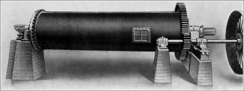 Fig. 75: Newell Riveted Tube Mill - not installed at Aberthaw. Fig. 75: Newell Riveted Tube Mill - not installed at Aberthaw. |
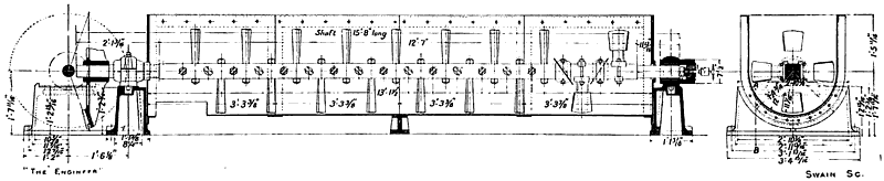
The slurry pumps do not require much description. A view of a pair of them is shown in Fig. 76. They are of the three-throw vertical type, with plungers 8in. in diameter and 16in. stroke. Each is self-contained on a cast iron bed plate and each is driven by belt through machine-cut double gearing. They receive their power from a motor through a counter-shaft, and fast-and-loose pulleys with hand wheel worked striking gear are provided. The three pump cylinders of each set are mounted on a rectangular pump box, to the bottom of which are attached three suction pipes, which are taken to the sump, each pipe having its non-return suction valve. The discharge is through delivery valves of the disc type into a chamber common to the three pump barrels, and the outlet from this chamber is fitted with a pendulum type of retaining valve. The pumps are very stoutly made and designed for working pressures up to 200 lb. on the square inch. A lever safety valve is attached to the pump box, which can be adjusted to suit the working pressure. As a matter of fact, the actual working pressure at Aberthaw is nothing like 200 lb. on the square inch. In lift alone, even to the doseage tanks, the maximum pressure is not a quarter of this, but with a substance like slurry it is best to be on the safe side and to provide plenty of margin.
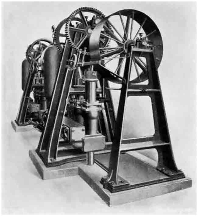 Fig. 76: Slurry Pumps. Fig. 76: Slurry Pumps. |
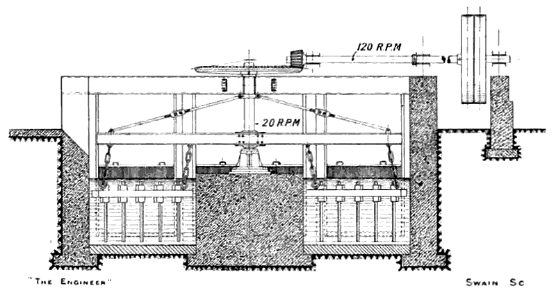
The delivery from the pumps is, it will be remembered, not ordinarily to the doseage tanks, but to the slurry mixers. The mechanical stirring mechanism, which was provided by Messrs. Newells, has already been fairly fully described in the account of the works. It may, however, be here repeated that a lattice girder, made up of heavy rolled steel joists and angles, and supported at its centre on a ball bearing so as to be free to revolve easily, carries depending from it four large skeleton paddles—two on each side of the central bearing. These paddles are made to revolve by gearing driven from an electric motor working on to a shaft running along the length of the girder, and the action of the paddles, which are separately rotated, is such that, owing to the consistency of the slurry, the girder, and with it the paddles, revolves slowly about the centre axis of the girder, the motion of the mixing apparatus as a whole being on the sun and planet principle. The pivot of the lattice girder rests on a pillar built up in the centre of the tank, and consists of a cast iron foundation plate on which is mounted a large ball bearing, protected from contact with the slurry, and provided with a cast iron hollow pillar or central sleeve secured at the top to the girder. The paddles are built up of rolled steel joists and angles, and each paddle revolves round its own mild steel centre shaft, which shaft is itself carried by suspension bearings attached to the main girder. The engravings—Fig. 64 ante and Fig. 78—will make the foregoing description perfectly clear.
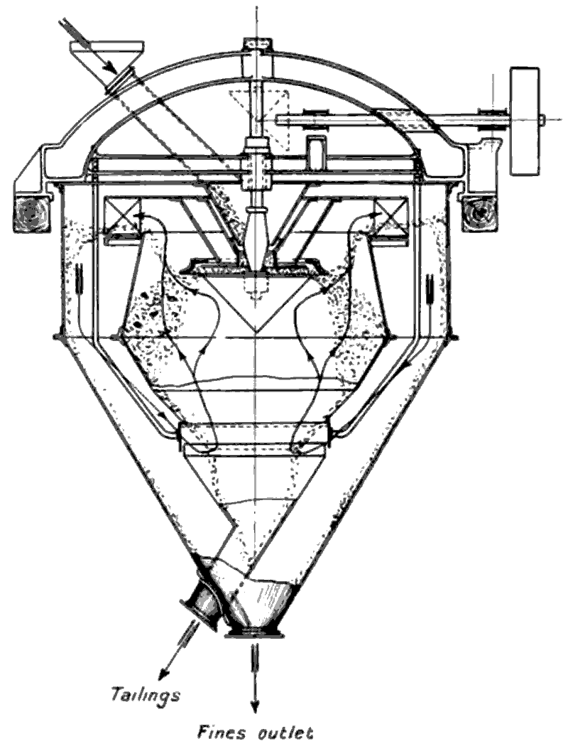
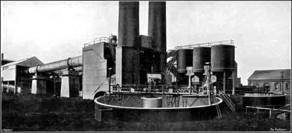 Fig. 78: Dosage tanks, slurry mixers, kilns and coolers. This inexpertly modified image was probably based on a photograph taken before the nearer (No 2) mixer had been completed. Despite its faults, it was used in Newell's advertising, presumably relying on the prospective audience's lack of appreciation that the centre post of a mixer is, as the term implies, in the centre. Fig. 78: Dosage tanks, slurry mixers, kilns and coolers. This inexpertly modified image was probably based on a photograph taken before the nearer (No 2) mixer had been completed. Despite its faults, it was used in Newell's advertising, presumably relying on the prospective audience's lack of appreciation that the centre post of a mixer is, as the term implies, in the centre. |
The feed of slurry from the mixers to the kilns is brought about by two sets of three-throw plunger force pumps, which are exactly similar to those already described, and hence call for no further description. There is also no need to refer again to the method of feeding the kilns, which was described in detail in the general article on the works—see above—and so we come to the kilns themselves. With regard to them we may say at the outset that we have never anywhere seen a better pair of kilns. Both in construction and in mounting they are excellent examples of high-class engineering work, and would more than hold their own in competition with any foreign-made kilns. British firms may have had to pass through troublous times (Note 28) in learning how to build rotary kilns successfully, but they have certainly acquired the requisite knowledge, and in this department as in the case of other branches of cement machinery they have already equalled, if, indeed, they have not gone ahead of their foreign rivals. The two kilns at Aberthaw are not the longest made (Note 29), but they are each of them 200ft. long by 10ft. diameter in the burning zone, and 9ft. diameter in the remainder of their length (Note 30). They are inclined at an angle of 1 in 25. The steel shell of the tube is ¾in. thick, and each kiln is carried on five wide cast steel riding rings or tires, which rest on two roller bearings mounted on bed-plates. These riding rings are not attached directly to the shell of the tube, but are carried on chairs, which are themselves bolted at intervals round the tube. Moreover, the rings are not a tight fit on the chairs, for a distinct clearance space has been provided, so that the rings themselves can revolve on the kiln, and, as a fact, do so to a slight extent, the bearing surfaces of the chairs and the inner peripheries of the rings being lubricated to facilitate motion. In this way any ill-effects due to expansion—which were among the troubles met with in the early days—are entirely counteracted. Fig. 77 is a view of part of one of the kilns, showing one of the riding rings and the rollers on which it rests. Where the roller rings come the kiln shell is reinforced under the chairs by means of ¾in. mild steel wrapper plates. In fact, the kilns are as complete as present-day science can make them, and we understand that they have given no trouble whatever from the time they started to work until now. They are, moreover, entirely free from "twist", which is a defect from which kilns made by the best of foreign makers have been known to suffer, and one of the effects of which is to wrench the lining out of position and reduce the length of its life.
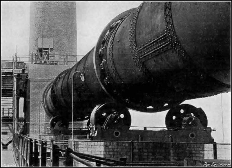 Fig. 77: View of Kiln 2 back end showing tyre and roller. Fig. 77: View of Kiln 2 back end showing tyre and roller. |
For some distance down the interior of the kiln at the feeding end, buckets and lifter plates are arranged so as to lift up the slurry and to allow it to fall down through the upcoming hot gases in streams, and thus to expose the maximum quantity of material to the drying action of these gases (Note 31).
The kiln is revolved by means of a motor acting through gearing on to a heavy cast steel spur-toothed ring mounted in an elastic manner on the kiln. This mounting consists of plates riveted to the kiln shell and projecting tangentially from it. The toothed ring, therefore, is not in direct contact with the kiln, and is hence protected from excessive heat and from the heavy expansion which would result from such contact. The cast steel spur gear wheels which transmit the power of the motor to the kiln and reduce the speed are mounted on the kiln foundations and practically work immersed in oil. They are a fine bit of work and show no signs of wear whatever. They are quite silent in operation. It will be realised, of course, that the reduction in speed from the motor to the kiln is very considerable. The speed of the motor, which is of 50 horse-power, can be controlled between 365 and 730 revolutions per minute, the corresponding speeds of the kiln being from ¾ to 1½ revolutions, and the normal speed one revolution per minute. So as to prevent longitudinal movement of the kilns thrust rollers which bear against the sides of the riding rings nearest the firing end are provided (Note 32).
Both kilns are lined from end to end with specially refractory firebricks arranged in varying thicknesses according to the temperatures met with. To these firebricks. which are known by the name of Adamantine, and which were supplied by Charles Davison and Co., Limited, of Ewloe, near Chester, we allude in a subsequent article.
It may interest our readers if we state that what was, we believe, the first rotary kiln put to work in this country was that erected at Mitcheldean. It was 15ft. long and 3ft. 6in. in diameter (Note 33). A few years ago Messrs. Newells took out this kiln and replaced it with another which was 120ft. long and 7ft. 6in. diameter, and which was at the time the largest in the United Kingdom. As showing what vast strides have been made since the small kiln was built, we may say that whereas it consumed about twice the weight of coal that it produced clinker, large modern kilns with good coal only use a weight of fuel representing some 27 per cent. of the weight of clinker burnt. Messrs. Newells are prepared to make kilns from 7ft. 6in. to 9ft. in diameter, with or without enlarged burning zones up to 10ft. diameter, and from 120ft. to 200ft. long (Note 34).
At the lower or firing end of each kiln is arranged a hood, made of mild steel and lined with refractory firebrick, which fits over the end of the kiln and can be run back on travelling wheels, and a hole in the centre of which the burning nozzle projects into the kiln. There is an aperture in the bottom of this hood to allow the calcined slurry or clinker to fall down in the cooling drum. A clinker cooling drum is provided for each kiln and each is arranged immediately under its own kiln. These cooling drums are very similar to the kilns themselves, both in construction and operation. Each is a long tube or cylinder built up of ½in. steel plate, the length being 82ft. and the diameter 6ft. 6in. for the greater part of the length, but increased at the upper end to 7ft. 6in. (Note 35), where there is a lining of refractory firebrick. For the remainder of the length the lining is of cast iron. Cast iron Z section lifting plates are arranged longitudinally around the internal periphery of the coolers, and these lift the clinker nodules and let them fall in showers through the current of cold air which passes up through the cooler on its way to the kiln. Each cooler is arranged at a slope of 1 in 14, and each is revolved at a speed of about one revolution per minute by cast steel gearing, exactly as are the kilns, the necessary power being derived from an electric motor. As in the case of the kilns thrust rollers bearing against the riding rings are provided to counteract any tendency of the coolers to move longitudinally. At the delivery end of each cooler, which is immediately above a plate conveyor, is arranged a circular grid. This, while allowing the well-burnt clinker to pass through, prevents large imperfectly-burnt pieces from doing so. However well a kiln may be managed it is practically impossible to avoid having these partially burnt lumps sometimes, though it is by no means always that they are removed as at Aberthaw. In a good many works we have seen they are allowed to go on to the grinding plant, it being considered that, representing as they do a comparatively small proportion of the total volume of the clinker, their inclusion will have no noticeable effect on the finished cement. It is, however, undoubtedly the best practice to remove them. It may here be said that the lifting plates, which we mentioned as being arranged near the feeding end of the kiln, are provided very largely with the view of keeping the drying slurry well broken up and hence of preventing the formation of lumps which the revolving motion of the kiln must tend to produce (Note 36).
In Fig. 78 is given a comprehensive view which shows on the right hand side the two slurry mixers with the three dosage tanks between them and on the left the kilns with the coolers beneath them, the feeding platform and the two chimneys coming in the centre. The plant has been designed to produce 120,000 tons of cement in the course of a year, which means a continuous daily output from each kiln of nearly 165 tons, or, say, 1150 tons per week. We may add that the smallest cooler of the type used at Aberthaw which Messrs. Newells ordinarily make is 3ft. 6in. in diameter and 40ft. long (Note 37), and the largest is 6ft. 6in. and 7ft. 6in. in diameter and 82ft. long.
The kilns at Aberthaw are coal fired. The arrangement for bringing the coal on to the site have already been described, and the passage of the coal through the various processes has been briefly alluded to in a foregoing article. It now remains to describe the different machines which are employed. The coal is first of all raised from the underground bunkers, in which it has been deposited by railway trucks, by means of a bucket elevator which discharges into a mild steel hopper arranged immediately over a set of crushing rolls. These rolls are of Messrs. Newell's standard design, which has already been described and illustrated in Fig. 73. They break up the coal into quite small pieces, which are discharged into a feed hopper over a table feeder. The latter is of exactly the same type as that employed for feeding the raw material grinding mills. The table delivers the coal in a regular stream into the coal dryer.
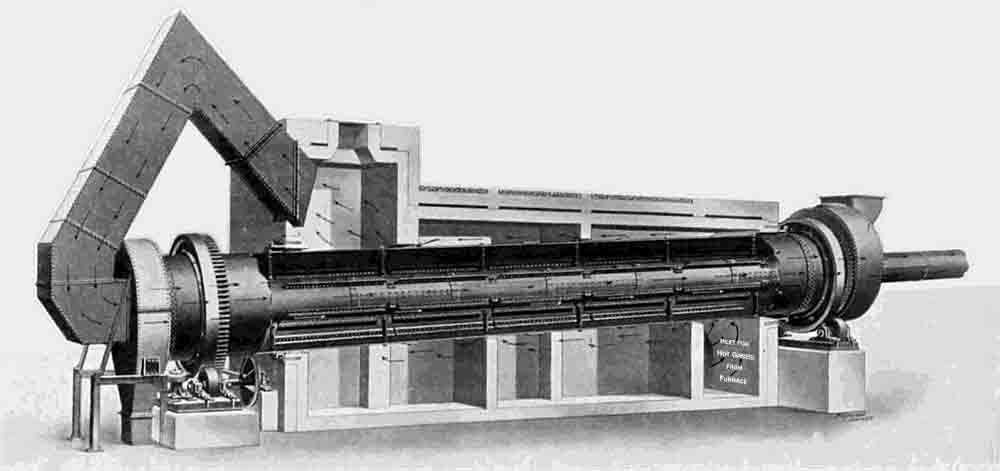 Fig. 79: Newell's Double Tube Coal Dryer. Fig. 79: Newell's Double Tube Coal Dryer. |
The coal dryer is of the double drum rotary type, It is 50ft. long and is made up of an outer mild steel shell 6ft. in diameter and an inner steel tube 2ft. 6in. in diameter. It is mounted in brickwork in such a manner that the hot gases from a furnace are first of all made to travel inside the brick setting and to be in contact with the exterior of the outer cylinder, and then to return along the inside of the inner tube to the chimney, which is situated at the feed end of the dryer. Meanwhile, the coal is fed from a feeding hopper through a shoot into the annular space between the two tubes so that it is acted upon by heated surfaces practically all round it. In its passage down from the top to the bottom of the dryer it is being continuously lifted and showered by lifting plates attached to the interior wall of the outer tube. It thus obtains the maximum possible effect of the heat from the hot gases on either side of the annular passage. It may be explained that the inner drum is attached to the outer cylinder by means of suspension links so as to allow for any unequal expansion of the two drums. The furnace is built on to the brickwork setting which surrounds the dryer, to which it is connected by flues. The outer tube is carried by cast steel riding rings mounted on the tubes, which rings rest on cast steel rollers the bearings of which are fixed to cast iron bed plates. A thrust roller is supplied, as in the case of the kilns and coolers, to limit the axial travel of the drum, which is set at an angle of one in 20. The rotation of the tube, which is at a speed of about 5 revolutions per minute, is effected by means of belt pulleys and bevel gears with a spur pinion engaging a toothed gear ring attached to one of the riding rings, the necessary power being obtained from a 20 brake horse-power motor. The whole arrangement is well shown in Fig. 79. This size of dryer is capable of dealing with about 10 to 12 tons of coal per hour, reducing an original water content from some 10 per cent. to about 2 per cent. or under (Note 38). The sizes of dryers of this type ordinarily made by the firm vary from 3ft. 6in. in diameter and 20ft. long to 6ft. in diameter and 60ft. long. At Aberthaw the coal is, as we have explained, dried by gases from a separate furnace. Messrs. Newells are however, prepared to supply dryers heated in other ways, such, for example, as by means of producer gases or by hot gases from the kiln.
The dried coal leaves the outlet end of the dryer by means of a gravity shoot and is taken by a spiral conveyor to the coal grinding mills. Arrived there it is lifted by an elevator and delivered by another conveyor into two feed hoppers which are arranged immediately over two feed tables, each of which feeds a ball mill. The feed tables are exactly similar to those used for the raw material and for the undried coal.
- o - O - o -
The two coal-grinding ball mills are of Messrs. Newell's standard type, known as "Lion" Ball Mills. They are illustrated in Figs. 80 and 81, the latter of which shows half of the mill in section. The drum is mounted on a steel shaft to which it is secured by two naves, the nave on the driving side being solid, while that on the feeding side is hollow and is provided with arms or ribs. The shaft is carried in bearings fitted with gun-metal steps, which are secured to sole plates fixed by bolts to the foundations. The mill is driven by spur reduction gearing. The countershaft carries fast and loose pulleys and a shrouded pinion which gears with the drum shaft. The latter forms the axis of the revolving drum, which latter is keyed to it as is also the large spur wheel for receiving power from the pinion shaft. A feed hopper, which is secured to the sole-plate of the drum shaft bearing, is fitted to the hollow nave at the feeding side of the drum. This hopper may, under certain circumstances, be furnished with a regulating feeding device.
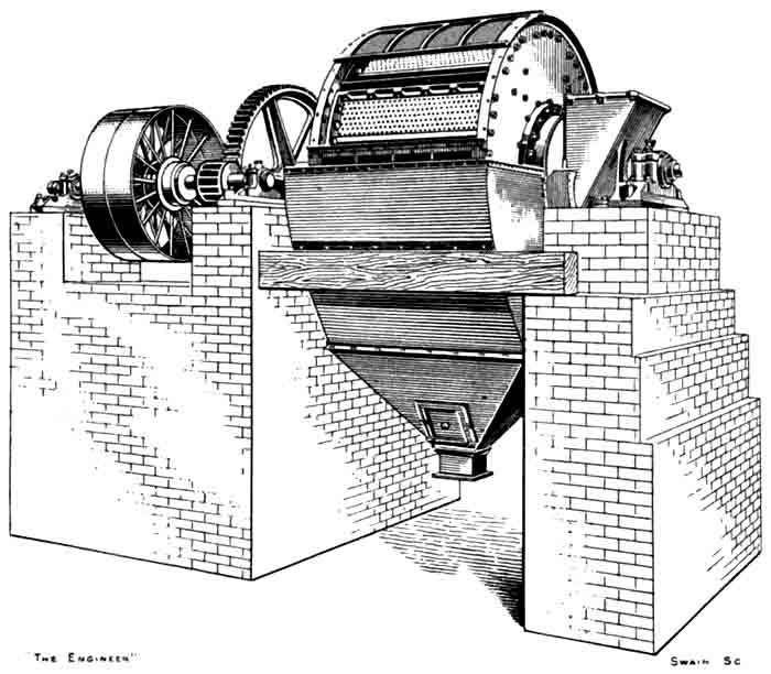 Fig. 80: Newell's Lion Ball Mill. Fig. 80: Newell's Lion Ball Mill. |
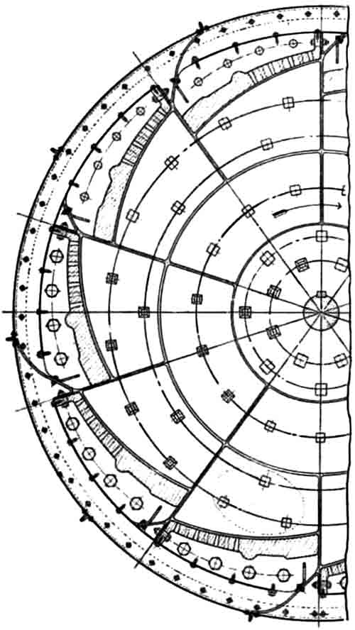 Fig. 81: Part section of ball mill. Fig. 81: Part section of ball mill. |
The side or end plates of the grinding drum, which are secured to the naves and carried by the drum shaft, are of rolled steel and are lined with hard steel protection plates. The stepped grinding plates, which are of cast steel, are arranged circumferentially round the drum, as may be seen in the section Fig. 81. The faces of these plates are partly flat and partly radiated, one half of each plate being solid and the other half perforated with taper holes. Scoops and guard plates are fitted to each grinding plate. At a short distance from the grinding plates are arranged perforated screens and a little way further out still there are fine sieves fitted to steel frames, which are secured to the circumference of the drum, which latter is covered in by a dust casing constructed in a number of parts and provided with doors for the examination of the sieves and screens. The lower part of the dust casing is formed into a hopper, into which the ground material which has passed through the screens and sieves drops and from which it is discharged through a flanged outlet. The coarser material which has passed through the holes in the grinding plates, but which cannot get through the holes in the screen, is automatically returned by the motion of the drum, and the action of scoops to the interior of the drum, for further grinding, the pieces falling through the holes in the stepped part of the plates. In the same manner the tailings from the fine screen are also returned to the drum. The material delivered from the machine therefore must all have passed through the sieve, which is constructed to pass only fine grits. The grinding media are hard steel balls.
Messrs. Newell's make for stock six sizes of this type of mill, the particulars of which are given in the following table:
| General particulars | Size 0. | Size 1. | Size 2. | Size 3. | Size 4. | Size 5. |
|---|---|---|---|---|---|---|
| Diameter of grinding drum | 6'3" | 7'6" | 7'6" | 8'10½" | 10'0" | 10'0" |
| Width of grinding drum | 3'3" | 3'11" | 4'6½" | 4'6½" | 5'6" | 6'6" |
| Revolutions per minute | 27 | 25 | 25 | 21 | 21 | 18 |
| Brake horse power | 12 | 20 | 27 | 37 | 45 | 50 |
| Weight of mill with balls, cwt | 148 | 202 | 230 | 310 | 335 | 360 |
| Weight of balls, cwt | 14 | 22 | 27 | 40 | 58 | 70 |
| DAWN Horsepower (Note 39) | 14 | 25 | 30 | 45 | 63 | 76 |
The discharge from each ball mill falls by gravity to a tube mill arranged immediately below it. These two tube mills are somewhat similar to the wet tube mills already described; they, however, differ in certain particulars. Thus, there is only one chamber instead of two and the grinding media are all flint pebbles. The tubes are 24ft. long by 6ft. in diameter and they are lined with silex bricks. The standard arrangement of one of Messrs. Newell's tube mills for dry grinding is shown in Fig. 82. These mills are supplied in exactly the same diameters and lengths as are the firm's wet tube mills, the only difference being that the horse-powers vary slightly in the two types. The end plates are domed in shape and are of cast steel. They are lined inside with hard cast iron wearing plates. Cast in one piece with the end plates are hollow trunnions, which serve the purposes of carrying the tube in its bearings and feeding and discharging the mill. The trunnion bearings are 21in. in diameter and 20in. long. They are babbitted and water-cooled. The inlet trunnion is furnished with an internal automatic screw feeding device for regulating the feed to the mill, while the outlet trunnion is lined in the bore with hard cast iron liners. A cast iron slotted grid plate is fixed near the delivery trunnion which, while it allows the powdered coal to pass, retains the grinding pebbles. The pulley driving the mill is 7ft. in diameter and 22in. in the face.
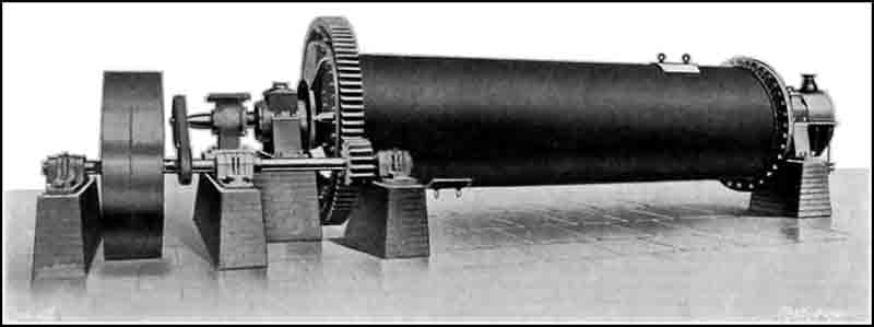 Fig. 82: Tube mill arranged for dry grinding. Fig. 82: Tube mill arranged for dry grinding. |
After being treated in these mills the coal is ground so finely that 95 per cent. of it will pass through a 100 by 100 mesh sieve (Note 40), and it is then in a condition to be used for firing rotary kilns. The pulverized coal dust on being discharged from the tube mill falls into a trough containing a spiral conveyor by means of which it is taken to the hopper of an encased 15in. bucket elevator which lifts it up and delivers it into the enclosed trough of a 12in. spiral conveyor which runs horizontally over the centres of two feeding hoppers, one of which is situated immediately over the centre line of each of the two kilns and a little to the rear of the kiln hood.
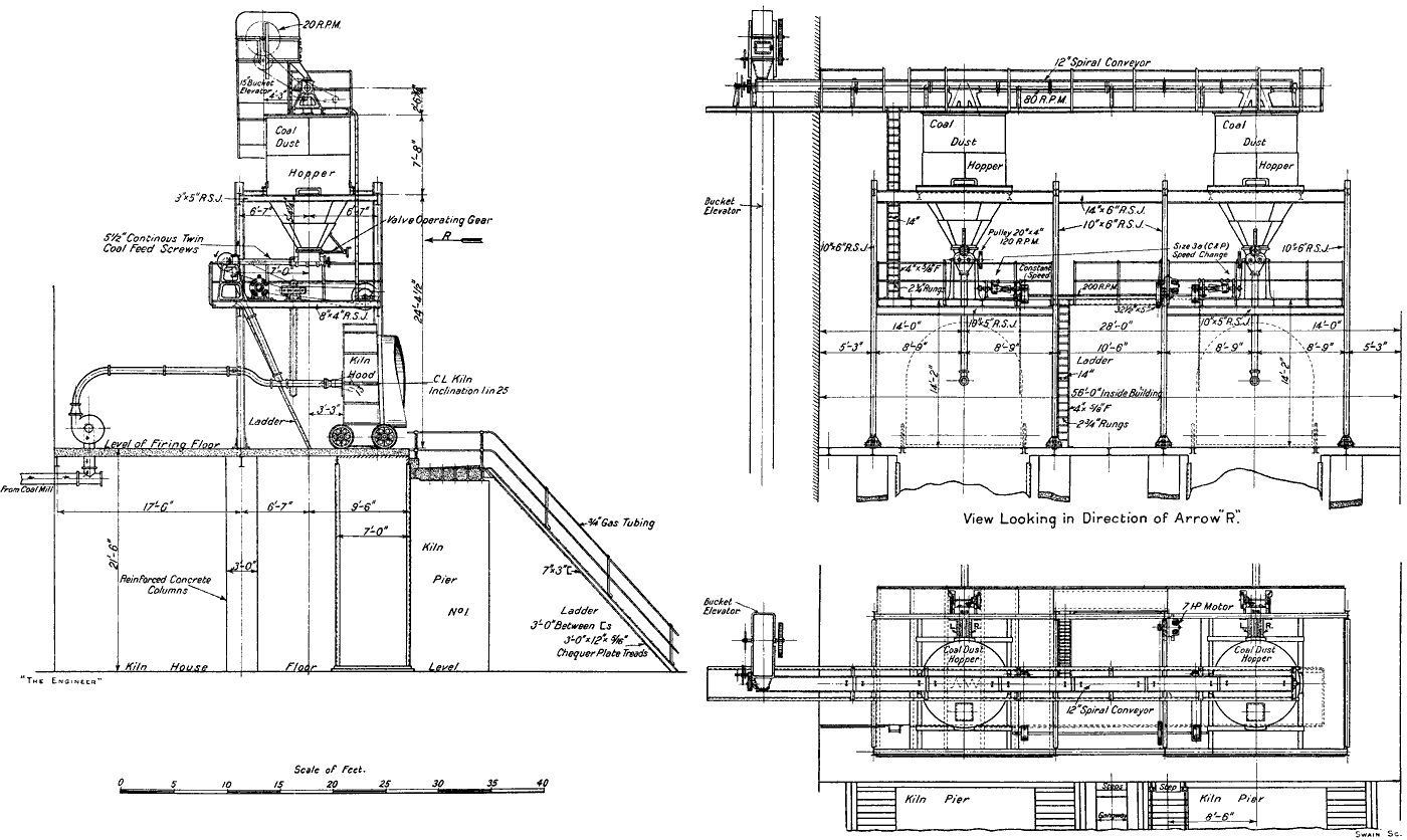 Fig. 87: Kiln coal feeding arrangements. See Note 41. Fig. 87: Kiln coal feeding arrangements. See Note 41. |
The arrangements for firing the kilns are shown in Fig. 87. The coal dust hoppers are shaped like inverted truncated pyramids. At the bottom of each is fixed a plate valve the opening of which can be varied by means of a chain which passes over a wheel and is taken down to the firing platform so as to be readily manipulated by the burner. Fixed immediately below this valve is a horizontal trough containing two 5½in. screw conveyors, which revolve in opposite directions. These screws are driven by motor through a double cone variable speed gear, which is also controlled by a chain going down to the burning platform. The burner has, therefore, two means of controlling the amount of coal being supplied to his kilns. As a matter of fact, two such means are not an absolute necessity and the burner is usually found to content himself by manipulating one of them, but it is, of course, a safeguard to have two.
 Fig. 83: Coal dust feeding device. The firing pipe is under high pressure to impart a large momentum to the flame in the kiln. The venturi puts the fine coal feed pipe under suction, preventing fine coal from blowing back through the screws and leaking out at the joints. |
The discharge from the trough containing the twin spirals falls into a pipe which delivers it into the top of the firing nozzle pipe some little way back from the point where the latter is taken through the hood of the kiln (Note 41). Just below the pipe coming down from the spirals is arranged a distributor as shown in Fig. 83. This is in the form of a taper tube fitted inside the main air pipe in such a position that the smaller end of the tube is just in front of the point where the powdered coal falls in (Note 42). Along the main air pipe and through the distributor tube is passed a continuous blast of air furnished by a centrifugal fan, and in this way the coal dust is taken along by the air current and injected into the kiln. The centrifugal fan draws its supply of air from the coal mill house. This arrangement not only helps to keep the latter free from impalpable coal dust but ensures the burning of the dust and hence increases the efficiency of the plant, though possibly only by a very little. The speed of the fan may be controlled by the burner from his platform as well as the speed of rotation of the kiln, so that any necessary adjustment can be made by him without his having to leave his post. The injection nozzles of the kiln are provided with spherical joints so that the burner can direct the flame to any desired part of the material coming down the kiln. This again furnishes another means of controlling the burning. It will be understood that there is a complete coal feeding plant, including extractors, variable speed gear, centrifugal fan, &c., for each kiln.
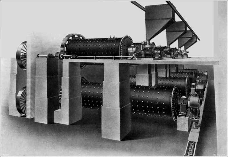 Fig. 84: Clinker grinding plant. |
The grinding of the clinker to produce the finished cement is, of course, a most important operation. At Aberthaw it is carried out in two stages, and the plant employed consists of four steel ball tube mills and four tube mills. The steel ball tube mills are as their name implies, tube mills in which the grinding media are steel balls of various sizes. They are, however. shorter and of stiffer build than the tube mills already described. The steel ball tube mills at Aberthaw are 17ft. long and 6ft. 2in. in diameter. The shell is made of a seamless steel tube and the end covers are dome shaped and of cast steel. The lining is of cast steel plates. The arrangement of the clinker grinding plant is shown in Fig. 84. The feed to the steel ball tube mills may be either by means of a table feed as shown, which has already been described, or by a jigging or shaker feed arrangement, such as is shown in Fig. 85. The apparatus consists of a mild steel trough suspended from a cast iron frame and capable of being shaken or jigged by means of an eccentric. To the end of the trough is attached a second and similar trough which projects into the hollow trunnion at the feed end of the mill. The clinker gravitates from the storage hopper through the aperture in the cast iron frame on the upper trough and, when the latter is stationary, the flow of material is checked, whereas, when the shaking operation is in motion, the material progresses along the troughs into the mill. The stroke of the eccentric is adjustable, and hence the rate of feed can be varied at will while the mill is operating. Some such devices as the foregoing or their equivalents are absolutely essential to the proper working of a cement grinding plant, for, unless the feed is steady and regular, the resulting cement will not be round regularly and evenly.
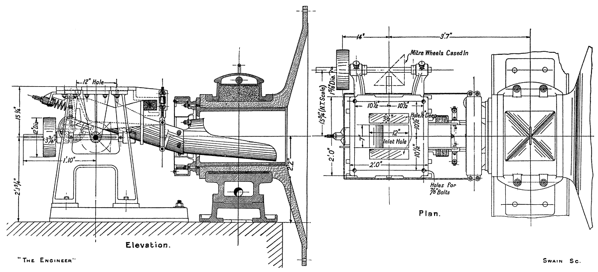 Fig. 85: Shaker feed for tube mills. The early mills, being comparatively small, had correspondingly small trunnions, and getting the feed through them was a major difficulty. |
The clinker-finishing mills to which the discharge from the steel ball tube mills falls by gravity are very similar indeed to the finishing mills for coal grinding and their chief point of difference is that their lining is of hard cast iron, whereas that in the coal mills is of silex. The clinker finishing mills are 26ft. long and 6ft. 2in. in diameter (Note 43) and their methods of feeding and discharging are absolutely identical with that of the coal plant and need not be again referred to. The grinding media are flint pebbles.
The product of these mills is the finished cement and it is taken away by a system of conveyors and elevators to the cement silos as already explained. The mills were, at the time of our visit, operating extremely well, and we gathered that they had always done so and that there had never been any trouble or difficulty in getting them to grind the cement down to any degree of fineness. The residue on a 180 by 180 mesh sieve at the time of our visit was some 7½ per cent. At that time the British Standard Specification allowed a maximum residue of 18 per cent. This has since been reduced to 14 per cent., so that the residue at Aberthaw in ordinary working is only just over half of that maximum.
The grinding of rotary kiln clinker in two processes by the method just described enables steam or water to be introduced into the finishing mill. This is, in some cases, not only advantageous but necessary in order to produce cement which will conform with the requirements of the British Standard Specification (Note 44). There are cases, however, when this is unnecessary, and in such instances a combined tube mill can be economically and efficiently used. Messrs. Newells manufacture such a mill under licence from a patentee (Note 45) and an external view is given of one of them in Fig. 86. It consists of a long steel tube, the first and shorter portion of which is lined with steel plates and charged with steel balls. The clinker is reduced to a coarse powder in this portion of the mill and is then discharged into a screening chamber. In the latter the more finely ground material passes through a screen and is led to the second and longer portion of the tube mill, which may be lined either with flint stone or hard cast iron and which is charged with flint pebbles. The tailings from the screening chamber travel back and are delivered through openings at the feeding end of the first chamber.
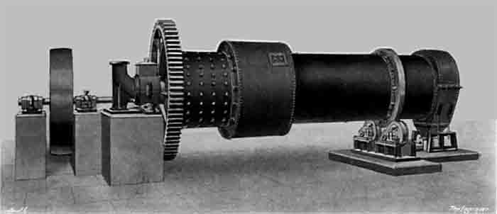 Fig. 86: Newell's chamber grinding mill. |
Messrs. Newells point out that when it is possible to use a mill of this type the horse-power per ton of cement ground is materially reduced and there is also a sensible economy, not only in the foundations, but also in the height of the building, as well as a reduction in the length of the elevator, and only one belt is necessary instead of two.
In the foregoing we have sought to give some idea of the machines in operation at Aberthaw, but we have been forced by reasons of space to pass over, with a bare mention, many pieces of apparatus and devices which are employed. It may be here repeated, however, that the whole of the cement-making machinery at these works with the exception of the feeding mechanism to the stone breakers, which was specially designed by Mr. Day, the consulting engineer, the raw stone conveyor, and the clinker conveyor were supplied by Messrs. Newells. Into the question of why the two conveyors were not supplied by this firm we need no go, but we can say this, that it was certainly not because it was unable to make them for its conveyors which are in operation are of first-rate quality and workmanship.
At the risk of being accused of repeating ourselves we feel that we must say again, in conclusion, that the machinery in operation throughout the Aberthaw works—which, with the exceptions we have mentioned, is entirely British—is of such quality that it could not be beaten by any foreign competitor; nor could any foreign machinery turn out better cement. It is interesting to be able to state, moreover, that a record was created in the erection of the works. At the end of January, 1913, the site was absolutely untouched (Note 46), yet the works were in operation and manufacturing cement in the beginning of May, 1914, since which time they have continued to run with uniformly good results.